

dbx 576 User Manual
Vacuum Tube
Preamplifier
& Compressor
Owner’s Manual
Version 1.0
WARNING
FOR YOUR PROTECTION, PLEASE READ THE FOLLOWING:
WATER AND MOISTURE: Appliance should not be used near water (e.g. near a bathtub, wash-
bowl, kitchen sink, laundry tub, in a wet basement, or near a swimming pool, etc). Care should be
taken so that objects do not fall and liquids are not spilled into the enclosure through openings.
POWER SOURCES: The appliance should be connected to a power supply only of the type
described in the operating instructions or as marked on the appliance.
GROUNDING OR POLARIZATION: Precautions should be taken so that the grounding or
polarization means of an appliance is not defeated.
POWER CORD PROTECTION: Power supply cords should be routed so that they are not likely to be walked on or pinched by items placed upon or against them, paying particular attention to
cords at plugs, convenience receptacles, and the point where they exit from the appliance.
SERVICING: To reduce the risk of fire or electric shock, the user should not attempt to service the
appliance beyond that described in the operating instructions. All other servicing should be referred
to qualified service personnel.
FOR UNITS EQUIPPED WITH EXTERNALLY ACCESSIBLE FUSE RECEPTACLE:
Replace fuse with same type and rating only.
MULTIPLE-INPUT VOLTAGE: This equipment may require the use of a different line cord,
attachment plug, or both, depending on the available power source at installation. Connect this equipment only to the power source indicated on the equipment rear panel. To reduce the risk of fire or
electric shock, refer servicing to qualified service personnel or equivalent.
SAFETY INSTRUCTIONS
NOTICE FOR CUSTOMERS IF YOUR UNIT IS EQUIPPED WITH
A POWER CORD.
WARNING: THIS APPLIANCE MUST BE EARTHED.
The cores in the mains lead are coloured in accordance with the following
code:
GREEN and YELLOW - Earth BLUE - Neutral BROWN - Live
As colours of the cores in the mains lead of this appliance may not correspond with the coloured markings identifying the terminals in your plug,
proceed as follows:
¥ The core which is coloured green and yellow must be connected to
the terminal in the plug marked with the letter E, or with the earth
symbol, or coloured green, or green and yellow.
¥ The core which is coloured blue must be connected to the terminal
marked N or coloured black.
¥ The core which is coloured brown must be connected to the terminal
marked L or coloured red.
This equipment may require the use of a different line cord, attachment
plug, or both, depending on the available power source at installation. If the
attachment plug needs to be changed, refer servicing to qualified service
personnel who should refer to the table above. The green/yellow wire shall
be connected directly to the unit's chassis.
WARNING: If the ground is defeated, certain fault conditions in the unit or
in the system to which it is connected can result in full line voltage between
chassis and earth ground. Severe injury or death can then result if the chassis and earth ground are touched simultaneously.
PostScript Picture
(EuroWiring Chart)
U.K. MAINS PLUG WARNING
A
moulded mains plug that has been cut off from the cord is unsafe.
Discard the mains plug at a suitable disposal facility. NEVER UNDER
ANY CIRCUMSTANCES SHOULD YOU INSERT A DAMAGED
OR CUT MAINS PLUG INTO A 13 AMP POWER SOCKET. Do
not use the mains plug without the fuse cover in place. Replacement
fuse covers can be obtained from your local retailer. Replacement fuses
are 13 amps and MUST be ASTA approved to BS1362.
The symbols shown above are internationally accepted symbols that warn of
potential hazards with electrical products. The lightning flash with arrowpoint in an equilateral triangle means that there are dangerous voltages present within the unit. The exclamation point in an equilateral triangle indicates that it is necessary for the user to refer to the ownerÕs manual.
These symbols warn that there are no user serviceable parts inside the unit.
Do not open the unit. Do not attempt to service the unit yourself. Refer all
servicing to qualified personnel. Opening the chassis for any reason will
void the manufacturerÕs warranty. Do not get the unit wet. If liquid is
spilled on the unit, shut it off immediately and take it to a dealer for service.
Disconnect the unit during storms to prevent damage.
ELECTROMAGNETIC COMPATIBILITY
This unit conforms to the Product Specifications noted on the Declaration of
Conformity. Operation is subject to the following two conditions:
¥ this device may not cause harmful interference, and
¥ this device must accept any interference received, including interference
that may cause undesired operation.
Operation of this unit within significant electromagnetic fields should be avoided.
¥ use only shielded interconnecting cables.
DECLARATION OF CONFORMITY
ManufacturerÕs Name: dbx Professional Products
ManufacturerÕs Address: 8760 S. Sandy Parkway
Sandy, Utah 84070, USA
declares that the product:
dbx 576
conforms to the following Product Specifications:
Safety: EN 60065 (1993)
IEC65 (1985) with Amendments 1, 2, 3
EMC: EN 55013 (1990)
EN 55020 (1991)
Supplementary Information:
The product herewith complies with the requirements of
the Low Voltage Directive 73/23/EEC and the EMC
Directive 89/336/EEC as amended by Directive
93/68/EEC.
dbx Professional Products
Vice-President of Engineering
8760 S. Sandy Parkway
Sandy, Utah 84070, USA
July 1, 1998
European Contact: Your Local dbx Sales and Service Office or
International Sales Office
68 Sheila Lane
Valparaiso, Indiana
46383, USA
Tel: (219) 462-0938
Fax: (219) 462-4596

Table of Contents
Introduction................................................................................................................2
Features.......................................................................................................................2
Inspection....................................................................................................................3
Warranty.....................................................................................................................3
Connections.................................................................................................................4
Preamp Controls ........................................................................................................5
Compressor Controls...............................................................................................10
Rear Panel: Preamp.................................................................................................14
Rear Panel: Compressor .........................................................................................16
Specifications ............................................................................................................17
Settings Page.............................................................................................................20

Introduction
Thank you for purchasing the dbx 576 vacuum tube preamplifier and compressor. The 576 combines
high quality microphone and instrument preamplification with world-renowned dbx compression in
a single chassis to offer you a flexible input path to your audio devices.
The dbx 576Õs preamplifier circuit is a hybrid design consisting of a high-voltage class Avacuum tube
amplification stage, coupled with an ultra low noise, low distortion solid-state driver stage. The vacuum tube amplification stage is a classic, high plate-voltage design utilizing a pure class A topology.
A parallel-triode arrangement is employed, in addition to a fully-regulated plate supply to maximize
noise performance and transient response. The premium-grade 12AU7 vacuum tubes used in the dbx
576 are hand tested and graded specifically for gain, noise, and microphonics.
The compression section incorporates the features that have made dbx the standard for high quality
audio compression: Over Easyª compression curve, PeakPlusª limiting and the advanced dbx
V1ª VCA module that ensures high system performance. Precision 1% resistors are used throughout the audio path to ensure performance stability and low noise. To ensure years of trouble-free operation, each dbx 576 must pass a rigorous set of performance tests and a 24-hour burn-in period before
it is shipped from the factory.
We recommend that you take a moment to read through this operation manual. It provides valuable
information that will assist you in setting up and operating your dbx 576.
Features
¥ Flexible configuration; useful as a single comprehensive input section or dual discrete channels
¥ Low noise, pure Class A vacuum tube preamplifier stage with adjustable Drive and Level controls
¥ Flexible semi-parametric EQ stage with low cut, midband Q select and hardwire bypass
¥ PeakPlusª Limiter available on both channels
¥ Mic, Line and Hi-Z instrument inputs to preamplifier
¥ Class A Vacuum tube stage in compressor section with Drive control
¥ Selectable dbx OverEasy
¨
compression curve
¥ Pre-EQ insert loop in preamp section, Sidechain loop in Compressor section
¥ Multi-source VU metering and Peak indication
¥ Ready for optional dbx
TYPE IV
ª
Conversion System digital output module
2

Inspection
Verify that the 576Õs package contains the following:
¥ 576 Unit (according to Model number marked on package)
¥ AC Power Cord
¥ Operation Manual
¥ Registration Card
¥ Rack screws & washers
If any of these items are missing, contact dbx customer service at (801) 568-7660.
Warranty
This warranty is valid only for the original purchaser and only in the United States. We warrant dbx
products against defects in materials or workmanship for a period of two years from the date of original purchase for use, and agree to repair or, at our option, replace any defective item, except external power transformers, without charge for either parts or labor.
IMPORTANT: This warranty does not cover damage resulting from accident, misuse or abuse, lack
of reasonable care, the affixing of an attachment not provided with the product, loss of parts, or connecting the product to any but the specified receptacles. This warranty is void unless service or repairs
are performed by an authorized service center. No responsibility is assumed for any special, incidental or consequential damages. However, the limitation of any right or remedy shall not be effective
where such is prohibited or restricted by law.
Simply take or ship your dbx product prepaid to our service department. Be sure to include your sales
slip as proof of purchase date. (We will not repair transit damage under the no-charge terms of this
warranty.) dbx will pay return shipping.
NOTE: No other warranty, written or oral is authorized for dbx products.
This warranty gives you specific legal rights, and you may also have other rights which vary from
state to state. Some states do not allow the exclusion of limitations of incidental or consequential
damages or limitations on how long an implied warranty lasts, so the above exclusion and limitations
may not apply to you.
3
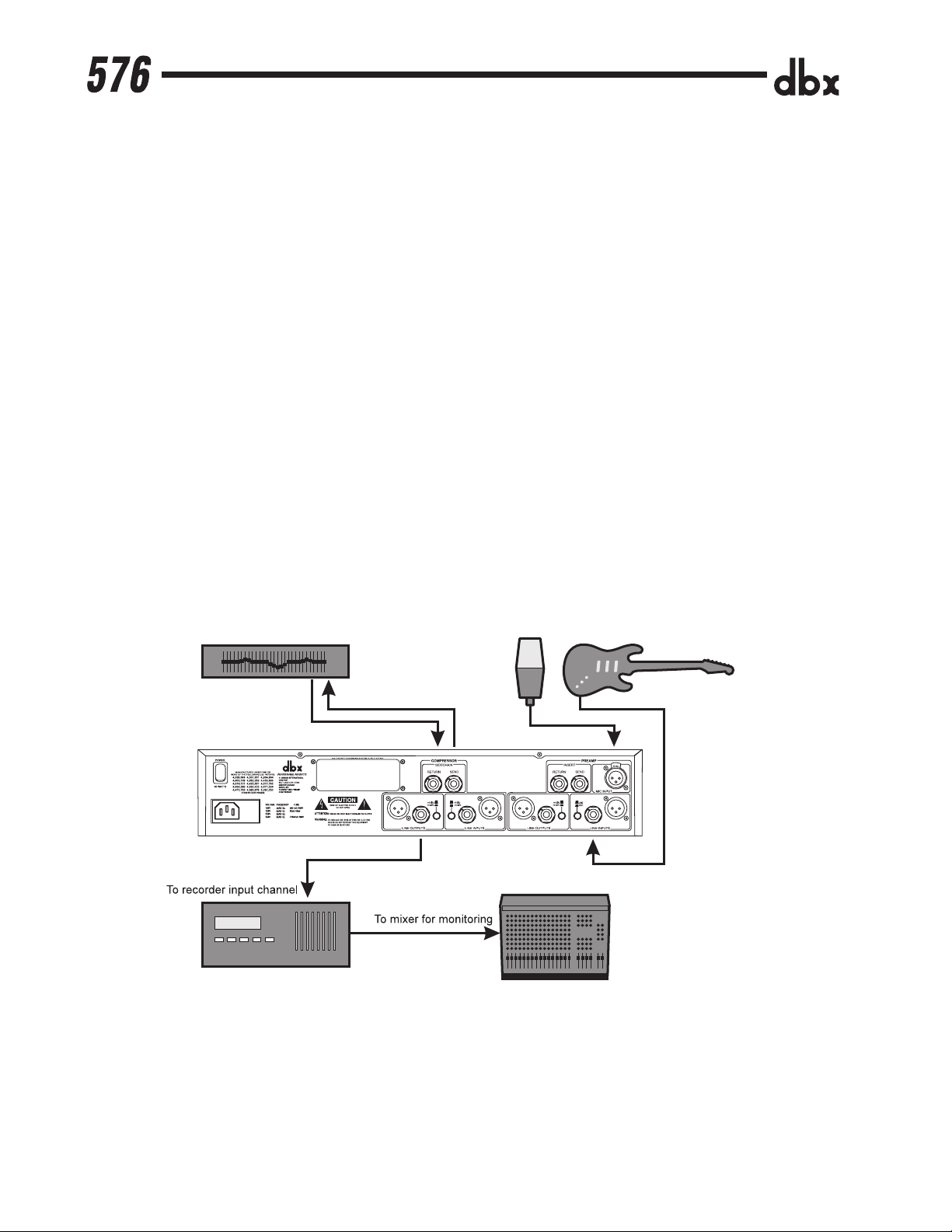
Connections
To connect the 576 to your system, refer to the following steps:
¥ Turn off all equipment before making any connections.
¥ Mount the 576 in a rack with the rack screws provided. The 576 can be mounted above or below
anything that does not generate excessive heat. Ambient temperatures should not exceed 95¼F
(35¼C) when equipment is in use. Although the unit is shielded against radio frequency and electromagnetic interference, extremely high fields of RF and EMI should be avoided where possible.
¥ Make audio connections via XLR, 1/4Ó TRS, or 1/4Ó TS plugs. Refer to Fig.1 for a typical studio
connection layout. The XLR and 1/4Ó TRS connectors on the inputs and outputs can be used for balanced or unbalanced connections. However, the use of more than one connector at a time on the
input pair could unbalance balanced lines, cause phase cancellations, short a conductor to ground,
or cause damage to other equipment connected to the 576.
¥ Verify that the fuse installed in the pull-out fuse holder of the fuse receptacle matches the type and
rating corresponding to the voltage in use as indicated on the rear panel of the 576.
¥ Apply power. Connect the AC power cord to the AC power receptacle on the back of the unit. Route
the AC power cord to a convenient power outlet away from audio lines. The unit may be turned on
and off from the rear panel power switch or from a master equipment power switch.
Figure 1: A typical 576 connection scheme
4
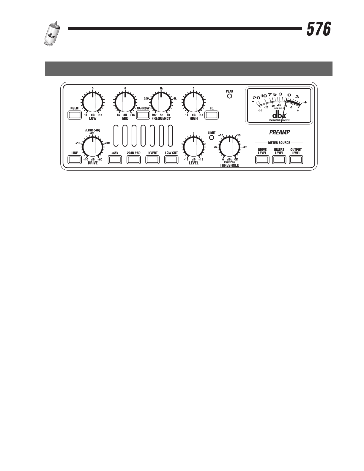
Preamp Controls
Figure 1: Preamp Section of the front panel
INSERT switch
This switch enables the rear panel insert loop by inserting any device connected to the Send and
Return jacks into the signal path. The insertion point is post-tube, pre-EQ. See page 15 for more
details on the Insert feature.
LOW control
This control varies the gain of the low frequency equalization; the gain range is -15 to +15 dB. The
low frequency filter is a shelving lowpass configuration with a knee frequency of 80 Hz.
MID control
This control varies the gain of the mid frequency equalization; the gain range is -15 to + 15 dB. The
mid frequency filter is a bandpass configuration with variable frequency and switchable bandwidth.
NARROW switch
This switch selects the bandwidth for the mid frequency filter. The default bandwidth is 1.5 octaves;
with the Narrow switch depressed, the bandwidth is 0.5 octaves.
FREQUENCY control
This control selects the center frequency for the mid frequency filter. The frequency range is 100 Hz
to 8 kHz.
HIGH control
This control varies the gain of the high frequency equalization; the gain range is -15 to +15 dB. The
high frequency filter is a shelving highpass configuration with a knee frequency of 12 kHz.
5
 Loading...