

Page 1
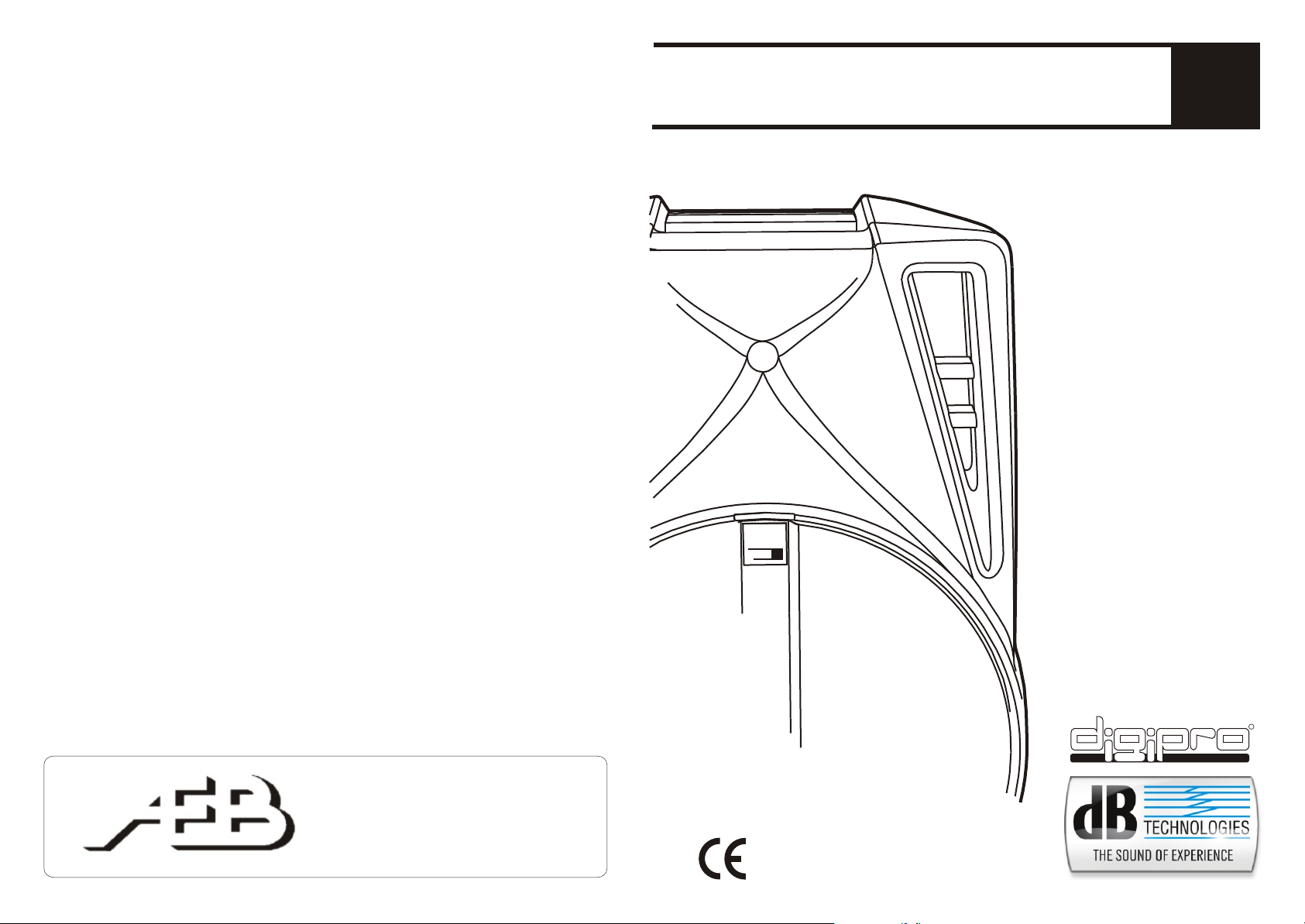
OPERAOPERA
OPERAOPERA
DD
PROFESSIONAL ACTIVE SPEAKER
DD
A.E.B. INDUSTRIALE s.r.l.
Via Brodolini, 8 - 40056 Crespellano (Bo) - ITALIA
Tel. + 39 051 969870 - Fax. + 39 051 969725
Internet: www.dbtechnologies.com
E-mail: info@dbtechnologies-aeb.com
MANUALE D’USO
USER MANUAL
BEDIENUNGSANLEITUNG
CARACTERISTIQUES TECHNIQUES
Made in Italy
RR
digital power
COD. 420120167
Page 2

IMPORTANTI ISTRUZIONI DI SICUREZZA
AVVERTENZA: PER RIDURRE IL RISCHIO DI SCOSSA
ItalianoItalianoItaliano
Manuale d’usoManuale d’uso
1
ATTENZIONE: PER RIDURRE IL RISCHIO DI INCENDIO O DI
IMPORTANTE
Il presente manuale costituisce parte integrante del prodotto e deve accompagnare quest’ultimo anche
nei passaggi di proprietà, per permettere al nuovo proprietario di conoscere le modalità d’installazione e
d’utilizzo e le avvertenze per la sicurezza.
L’installazione ed utilizzo non in accordo con le prescrizioni e modalità contenute all’interno del presente
manuale d’uso esime il produttore da qualunque responsabilità di danni a persone, cose e strutture.
Leggere le seguenti istruzioni
Tutte le istruzioni di sicurezza e di funzionamento devono essere lette e comprese prima di mettere in
funzione l'apparato.
Tenere conto di tutti gli avvertimenti
Tutte le avvertenze sull'apparecchio e le istruzioni di funzionamento devono essere seguite fedelmente.
Inutilizzo prolungato dell’apparato
Nel caso in cui si preveda di non utilizzare l’apparato per lungo tempo, è buona norma disconnetterlo
dalla rete di alimentazione, riporlo nell’apposito imballo o ricoprirlo in maniera da evitarne l’esposizione
alla polvere.
Guasti e riparazioni
In caso di guasto dell’apparato, è assolutamente vietato per l'utente tentare di ripararlo o rimuovere il
coperchio protettivo. Disconnettere l’apparato dalla rete di alimentazione e contattare l’assistenza
tecnica per la riparazione.
PRECAUZIONI PER L’INSTALLAZIONE E PER L’UTILIZZO
GENERALITA’
Conservare le istruzioni
Ai fini di un corretto impiego dell’apparato, il presente manuale d’istruzioni deve essere mantenuto con
cura per ogni futura esigenza di consultazione.
Posizionamento dell’apparato
Collocare l’apparato in posizione stabile e sicura in modo da evitare situazioni di pericolo a cose,
persone e strutture.
Messa a terra di protezione
L’apparato è realizzato in Classe I di protezione contro la scossa elettrica e il collegamento alla rete di
alimentazione deve essere effettuato ad una presa provvista del conduttore di terra di protezione. Prima
di effettuare la connessione elettrica dell’apparato, assicurarsi che l’impianto di distribuzione di rete sia
conforme alle norme vigenti in materia di impianti elettrici.
Alimentazione
L'apparato deve essere collegato ad una sorgente di alimentazione del tipo e con le caratteristiche
indicate nei dati di targa riportati sull'apparecchio stesso e specificati nel presente manuale (Vedere
specifiche tecniche). Prima di collegare la spina di alimentazione assicurarsi che la tensione sia del tipo
richiesto dall’apparato.
Cavo di alimentazione
Al fine di garantire la sicurezza d’utilizzo dell’apparato utilizzare esclusivamente il cavo di alimentazione
fornito a corredo avendo cura di posizionarlo e proteggerlo in modo da evitarne il danneggiamento
durante l’utilizzo. In caso di danneggiamento contattare l’assistenza tecnica e richiederne la
sostituzione. Non utilizzare cavi diversi da quelli in dotazione.
ELETTRICA, NON TOGLIERE IL COPERCHIO
(O IL PANNELLO POSTERIORE). ALL’INTERNO
NON SONO CONTENUTE PARTI RIPARABILI
DALL’UTENTE; AFFIDARE LE RIPARAZIONI A
PERSONALE QUALIFICATO.
SCOSSA ELETTRICA, NON ESPORRE
QUESTO APPARECCHIO ALLA PIOGGIA O
ALL’UMIDITÀ.
Questo simbolo, dove compare, ha lo scopo di avvisare l’utente di presenza di tensione
pericolosa all’interno del prodotto che può essere di portata sufficiente a costituire un rischio di
scossa elettrica per le persone.
Questo simbolo, dove appare, ha lo scopo di avvisare l’utente di presenza di importanti
istruzioni d’uso e manutenzione (assistenza) nella documentazione che accompagna
l’apparecchio.
“CAUTION”
TO PREVENT ELECTRICAL SHOCK
DO NOT REMOVE COVER
“AVIS”
RISQUE DE CHOCH ELECTRIQUE
NE PAS OUVRIR
Acqua e umidità
L'apparecchio non deve essere installato in prossimità di zone con presenza di liquidi ( es. lavandini,
lavabi, docce, vasche da bagno, bordo piscine, pavimenti bagnati o in altre posizioni in presenza di
acqua e liquidi in generale).
Penetrazione di oggetti e di liquidi
L’apparato deve essere posizionato in un luogo appropriato. Evitare di posizionare oggetti e contenitori
di liquidi sopra l’apparato, un ribaltamento accidentale potrebbe causarne l’intrusione all’interno delle
griglie di raffreddamento con conseguente pericolo elettrico.
Ventilazione
Installare l’apparecchio in una posizione o zona adeguata, tale da garantire un sufficiente ricircolo
d’aria. Non ostruire o coprire le feritoie di aerazione e ventilazione o i dissipatori dell’apparato. E’ buona
norma installare l’apparato ad una distanza che garantisca una buona ventilazione tra gli apparati.
Sorgenti di calore
Non installare o utilizzare l'apparecchio in prossimita’ di sorgenti di calore .
Accessori e optional
E’ assolutamente vietato perforare il contenitore dell’apparato o fissare qualunque altro genere di
supporto meccanico mediante adesivo. In caso di installazioni particolari e in ogni modo non descritte
nel presente manuale, contattare il servizio tecnico per l’elenco degli accessori disponibili per
l’apparato.
Seguire tutte le istruzioni
Tutte le istruzioni contenute nel presente manuale devono essere seguite da parte dll’utilizzatore per un
corretto utilizzo e funzionamento dell’apparato. In particolare si pone l’attenzione su:
- Non forzare gli organi di comando (tasti, controlli, ecc.).
- evitare di far lavorare l’apparato in sovraccarico per lungo tempo.
Pulizia
Pulire solo con un panno asciutto. Per la pulizia delle parti esterne evitare l’uso di diluenti, alcool,
benzina o altre sostanze volatili.
COLLEGAMENTI
ATTENZIONE
- Per il collegamento dell’apparecchio si raccomanda di rivolgersi a personale qualificato ed
addestrato, ossia personale avente conoscenze tecniche o esperienza o istruzioni specifiche
sufficienti per permettergli di realizzare correttamente le connessioni e prevenire i pericoli
dell’elettricità.
- Per evitare il rischio di shock elettrici, l’amplificatore deve essere alimentato dalla tensione di
rete solo dopo aver terminato tutti i collegamenti.
- Prima di alimentare l’amplificatore è buona norma ricontrollare tutte le connessioni.
- Tutto l’impianto di sonorizzazione dovrà essere realizzato in conformità con le norme e le leggi
vigenti in materia di impianti elettrici.
SUGGERIMENTI
ATTENZIONE
- Per evitare che fenomeni induttivi diano luogo a ronzii, disturbi e compromettano il risultato
dell’installazione, i cavi che trasmettono segnali microfonici o segnali a livello linea (es. 0 dB/V)
devono essere schermati e non devono essere posti in prossimità di:
1) apparecchiature che producono forti campi magnetici (es. grossi trasformatori di
alimentazione).
2) conduttori dell’energia elettrica.
3) linee che alimentano diffusori.
Il presente apparato è conforme alle direttive Europee 2006/95/EC e 2004/108/EC ed è pertanto
provvisto di marcatura CE.
La rispettiva dichiarazione di conformità è disponibile presso AEB Industriale s.r.l.
CLASSIFICAZIONE EMI
In accordo alle normative EN 55103, l'apparato è progettato e idoneo all'utilizzo in ambienti
Elettromagnetici E3 o inferiori (E2, E1).
ItalianoItalianoItaliano
Manuale d’usoManuale d’uso
2
Page 3
DESCRIZIONE
ItalianoItalianoItaliano
Manuale d’usoManuale d’uso
I modelli della serie “OPERA D” utilizzano amplificatori digitali DIGIPRO di ultima
®
generazione; la serie completa è composta da tre diverse potenze 200W, 400W e 600W
per soddisfare qualsiasi tipo di applicazione.
Questi amplificatori, ad alta efficienza, permettono di ottenere elevate potenze di uscita
con pesi e ingombri ridotti. Grazie alla bassa potenza dissipata il raffreddamento del
modulo amplificatore avviene in modo statico, evitando l’uso di ventola.
Il preamplificatore digitale con DSP (Digital Signal Processing) gestisce l’incrocio audio tra
i componenti acustici, la risposta in frequenza, il limiter, e l'allineamento di fase. Un
selettore permette la scelta tra due diverse equalizzazioni, “FLAT” e “PROCESSED“ per
garantire alta versatilità nei diversi utilizzi.
Gli amplificatori DIGIPRO 400W e 600W utilizzano alimentatori in tecnologia switching
®
SMPS (Switched-Mode Power Supplies).
Tale tecnologia aumenta l’efficienza, dell’alimentatore e ne diminuisce il peso.
Il corretto funzionamento è segnalato dalla accensione di un indicatore luminoso di
colore blu, posto sul frontale del diffusore. Tale indicatore può essere disabilitato
seguendo una particolare procedura descritta nel paragrafo “LED frontale” (pagina 8)
OPERA 208D
Il diffusore attivo OPERA 208D è equipaggiato con un
amplificatore DIGIPRO in grado di erogare 150W
®
(RMS) per la sezione bassi e 50W (RMS) per la
sezione alti.
Il diffusore a due vie biamplificato è equipaggiato con
woofer 8” (voice coil 1,5”) e driver al Neodimio da 1”
(voice coil 1”) caricato con tromba asimmetrica
80°/65°x60°.
Il diffusore è in materiale plastico ed è dotato di una
maniglia superiore, incassata, che ne facilita il
trasporto.
O
O
P
P
E
E
R
R
A
A
D
D
Nella parte inferiore del box è presente un supporto
piantana standard (D36mm).
Il diffusore è stato progettato anche per l’utilizzo in
appoggio come monitor (con angolazione 43°).
dd
d
d
dd
BB
B
B
BB
T
T
T
T
T
T
EH
EH
E
E
E
E
C
C
C
C
C
C
H
H
H
H
N
N
N
N
N
N
O
O
O
O
O
O
L
L
L
L
L
L
O
O
O
O
O
O
G
G
G
G
G
G
I
I
I
I
I
I
E
E
E
E
E
E
S
S
S
S
S
S
OPERA 210D
Il diffusore attivo OPERA 210D è equipaggiato con un
amplificatore DIGIPRO in grado di erogare 150W
®
(RMS) per la sezione bassi e 50W (RMS) per la
sezione alti.
Il diffusore a due vie biamplificato è equipaggiato con
woofer 10” (voice coil 1,5”) e driver al Neodimio da 1”
(voice coil 1”) caricato con tromba asimmetrica
80°/65°x60°.
Il diffusore è in materiale plastico ed è dotato di una
maniglia superiore, rivestita in gomma, che ne facilita
il trasporto.
Nella parte inferiore del box è presente un supporto
piantana standard (D36mm).
Il diffusore è stato progettato anche per l’utilizzo in
appoggio come monitor (con angolazione 43°).
OPERA 410D
Il diffusore attivo OPERA 410D è equipaggiato con un
amplificatore DIGIPRO in grado di erogare 300W
®
(RMS) per la sezione bassi e 100W (RMS) per la
sezione alti.
Il diffusore a due vie biamplificato è equipaggiato con
woofer 10” (voice coil 2”) e un compression driver da
1” (voice coil 1,3”) caricato con tromba asimmetrica
80°/65°x60°.
Il diffusore è in materiale plastico ed è dotato di una
maniglia superiore, rivestita in gomma, che ne facilita
il trasporto.
Nella parte inferiore del box è presente un supporto
piantana standard (D36mm).
Il diffusore è stato progettato anche per l’utilizzo in
appoggio come monitor (con angolazione 43°).
CONDOTTI REFLEX
OPERAOPERA
DD
d
d
dd
d
d
B
B
BB
B
B
T
T
T
T
T
T
EH
EH
E
E
E
E
C
C
C
C
C
C
H
H
H
H
N
N
N
N
N
N
O
O
O
O
O
O
L
L
L
L
L
L
O
O
O
O
O
O
G
G
G
G
G
G
I
I
I
I
I
I
E
E
E
E
E
E
S
S
S
S
S
S
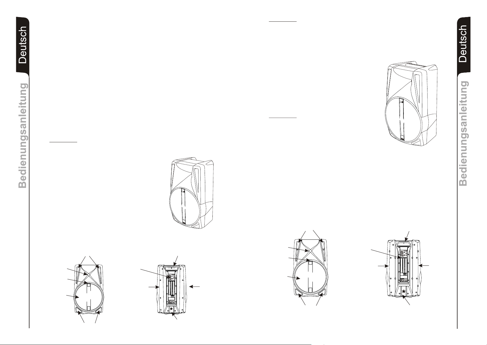
MANIGLIA
ItalianoItalianoItaliano
Manuale d’usoManuale d’uso
DRIVER
MANIGLIA
OPERA
D
TECHNOLOGIES
d
B
II
PIANO 43°
INDICATORE
LUMINOSO
WOOFER
DRIVER
INDICATORE
LUMINOSO
WOOFER
CONDOTTI REFLEX
AMPLIFICATORE
PIANO 43°
CONDOTTI REFLEX
3
CONDOTTI REFLEX
SEDE PIANTANA/STAFFA
Æ 36mm CON FISSAGGIO
AMPLIFICATORE
PIANO 43°
OPERA
D
PIANO 43°
TECHNOLOGIES
d
B
II
SEDE PIANTANA/STAFFA
Æ 36mm CON FISSAGGIO
4
Page 4
ItalianoItalianoItaliano
Manuale d’usoManuale d’uso
OPERA 402D
Il diffusore attivo OPERA 402D è equipaggiato con un
amplificatore DIGIPRO in grado di erogare 300W
®
(RMS) per la sezione bassi e 100W (RMS) per la
sezione alti.
Il diffusore a due vie biamplificato è equipaggiato con
woofer 12” (voice coil 2”) e un compression driver da
1” (voice coil 1,5”) caricato con tromba asimmetrica
80°/65°x60°.
Il diffusore è in materiale plastico ed è dotato di una
maniglia superiore, e due maniglie laterali rivestite in
gomma, che ne facilitano il trasporto.
Nella parte inferiore del box è presente un supporto
piantana standard (D36mm).
Il diffusore è stato progettato anche per l’utilizzo in
appoggio come monitor (con angolazione 43°).
OPERA 405D
Il diffusore attivo OPERA 405D è equipaggiato con un
amplificatore DIGIPRO in grado di erogare 300W
®
(RMS) per la sezione bassi e 100W (RMS) per la
sezione alti.
Il diffusore a due vie biamplificato è equipaggiato con
woofer 15” (voice coil 2”) e un compression driver da
1” (voice coil 1,5”) caricato con tromba asimmetrica
80°/65°x60°.
Il diffusore è in materiale plastico ed è dotato di una
maniglia superiore, e due maniglie laterali rivestite in
gomma, che ne facilitano il trasporto.
Nella parte inferiore del box è presente un supporto
piantana standard (D36mm).
Il diffusore è stato progettato anche per l’utilizzo in
appoggio come monitor (con angolazione 43°).
OPERA 602D
Il diffusore attivo OPERA 602D è equipaggiato con un
amplificatore DIGIPRO in grado di erogare 400W
®
(RMS) per la sezione bassi e 200W (RMS) per la
sezione alti.
Il diffusore a due vie biamplificato è equipaggiato con
woofer 12” al Neodimio (voice coil 3”) e un
compression driver al Neodimio da 1” (voice coil
1,75”) caricato con tromba asimmetrica 80°/65°x60°.
ItalianoItalianoItaliano
Il diffusore è in materiale plastico ed è dotato di una
maniglia superiore, e due maniglie laterali rivestite in
gomma, che ne facilitano il trasporto.
Nella parte inferiore del box è presente un supporto
piantana standard (D36mm).
OPE
RA
RAOPE
D D
Il diffusore è stato progettato anche per l’utilizzo in
appoggio come monitor (con angolazione 43°).
OER
OER
P A
P A
DD
OPERA 605D
Il diffusore attivo OPERA 605D è equipaggiato con un
amplificatore DIGIPRO in grado di erogare 400W
®
(RMS) per la sezione bassi e 200W (RMS) per la
sezione alti.
dd
dd
dd
BB
BB
BB
T
T
TEH
TEH
TEH
TEH
E
E
C
C
C O
C O
C O
C O
H
H
N
N
N
N
N
N
OL
OL
O
O
O
O
L S
L S
L S
L S
O
O
G
G
G
G
G
G
IS
IS
I
I
I
I
E
E
E
E
E
E
Il diffusore a due vie biamplificato è equipaggiato con
woofer 15” al Neodimio (voice coil 3”) e un
compression driver al Neodimio da 1” (voice coil
dd
dd
dd
BB
BB
BB
TH
TH
TE
TE
TE
TE
E
E
C
C
C O
C O
C O
C O
H
H
H
H
N
N
N
N
N
N
O
O
O
O
O
O
L
L
L S
L S
L S
L S
O
O
G
G
G
G
G
G
I
I
I
I
I
I
E
E
E
E
E
E
S
S
Manuale d’usoManuale d’uso
1,75”) caricato con tromba asimmetrica 80°/65°x60°.
Il diffusore è in materiale plastico ed è dotato di una
maniglia superiore, e due maniglie laterali rivestite in
gomma, che ne facilitano il trasporto.
Nella parte inferiore del box è presente un supporto
piantana standard (D36mm).
Il diffusore è stato progettato anche per l’utilizzo in
appoggio come monitor (con angolazione 43°).
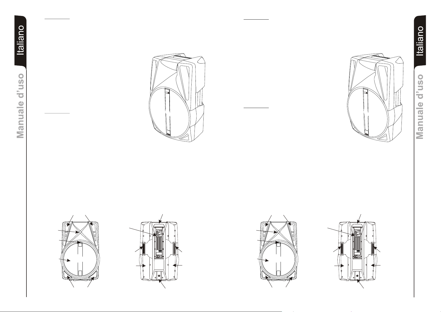
CONDOTTI REFLEX
AMPLIFICATORE
DRIVER
INDICATORE
LUMINOSO
WOOFER
PIANO 43°
5
CONDOTTI REFLEX
MANIGLIA
OPERA
D
TECHNOLOGIES
d
B
II
SEDE PIANTANA/STAFFA
Æ 36mm CON FISSAGGIO
MANIGLIAMANIGLIA
PIANO 43°
DRIVER
INDICATORE
LUMINOSO
WOOFER
CONDOTTI REFLEX
AMPLIFICATORE
PIANO 43°
CONDOTTI REFLEX
MANIGLIA
OPERA
D
TECHNOLOGIES
d
B
II
SEDE PIANTANA/STAFFA
Æ 36mm CON FISSAGGIO
MANIGLIAMANIGLIA
PIANO 43°
6
Page 5
COMANDI E FUNZIONI
1) CONNETTORI “Balenced Input” - “Link” - “Input- Link”
Questi connettori possono essere utilizzati come ingressi bilanciati per il
collegamento di microfoni bilanciati o sbilanciati o di sorgenti audio a livello linea
(0dB) (es. preamplificatore, mixer, registratore, lettore CD, strumento musicale, ...)
Questi connettori sono collegati in parallelo e possono essere utilizzati per rinviare il
segnale audio ad altri diffusori amplificati, registratori o amplificatori supplementari.
ItalianoItalianoItaliano
Manuale d’usoManuale d’uso
2) INDICATORE LUMINOSO “Limiter”
Questo indicatore s’illumina di colore rosso per indicare l'intervento del circuito
limitatore interno, il quale evita la distorsione dell'amplificatore e protegge gli
altoparlanti da sovraccarichi.
3) INDICATORE LUMINOSO “Signal”
Questo indicatore s'illumina di colore verde per indicare la presenza del segnale
audio (ad un livello medio di -20dB).
4) INDICATORE LUMINOSO “Ready”
Questo indicatore s'illumina di colore verde per indicare il corretto funzionamento
del diffusore.
Nel normale funzionamento il led è acceso fisso.
5) CONTROLLO SENSIBILITA’ INGRESSO “Sensitivity”
Questo controllo regola la sensibilità del segnale in ingresso all’amplificatore.
Tale controllo non influisce sul livello dell’uscita “Link” - “Input - Link”
6) SELETTORE MODE
Questo interruttore a due posizioni permette la selezione tra due diverse
equalizzazioni.
La posizione “Flat” permette di avere una risposta lineare del diffusore perfetta per
l’utilizzo in situazioni “live”.
La posizione “Processed” enfatizza le basse frequenze moderando le medie,
favorendo la riproduzione sonora di brani registrati.
7) SELETTORE SENSIBILITA’ “Input Sens”
Posizionare il selettore in LINE per l’utilizzo di una sorgente a livello linea (0dB) o
MIC per l’utilizzo di un microfono.
8) PRESA DI ALIMENTAZIONE “MAINS ”
Consente la connessione del cavo di alimentazione fornito in dotazione.
9) PORTA FUSIBILE “FUSE”
Alloggio per fusibile di rete.
10) INTERRUTTORE GENERALE “POWER”
L’interruttore permette l’accensione e lo spegnimento del diffusore.
FRONTALE DIFFUSORE
1) INDICATORE LUMINOSO
L’indicatore luminoso di colore blu indica lo stato del diffusore.
Raffreddamento
Il controllo termico è gestito dal microprocessore interno, che grazie a due sensori
controlla la temperatura dell’amplificatore e dell’alimentatore evitando il surriscaldamento
limitandone il volume generale.
In caso di surriscaldamento (> 80 gradi) il volume decresce in funzione dell’aumento della
temperatura rendendo impercettibile la variazione.
Il corretto volume e tutte le funzioni verranno riprese automaticamente al raggiungimento
delle normali temperature di esercizio.
LED frontale
Sul frontale è presente una indicazione luminosa (LED) di colore blu che indica lo stato del
diffusore.
E’ possibile disabilitare l’indicatore luminoso frontale del diffusore durante il normale
funzionamento nel caso in cui questo sia indesiderato, come in installazioni in teatro, al
cinema,ecc..
Per modificare lo stato dell’indicatore luminoso frontale è necessario premere e rilasciare
ripetutamente l’interruttore MODE durante la fase di accensione, quanto tutti i LED
(”Limiter”, “Signal” e “Ready”) sul modulo amplificatore sono spenti .
Per ripristinare la funzione dell’indicatore luminoso frontale ripetere l’operazione.
La diagnostica del diffusore collegata a questo indicatore luminoso, rimane sempre attiva
anche se il led è stato disattivato.
Accensione
Gli amplificatori sono equipaggiati con un microprocessore per la gestione del DSP e il
controllo dell’amplificatore.
La regolare accensione del diffusore è garantita da una procedura di inizializzazione;
durante questa fase di test, l’indicatore luminoso frontale Blu lampeggia 2 volte e i LED
(”Limiter”, “Signal” e “Ready”), posti sul modulo amplificatore, rimangono spenti per circa 2
sec.
Al termine della procedura di avvio, il LED frontale si illumina (se abilitato) e sul modulo
amplificatore solo il LED verde “Ready” rimane acceso fisso.
Nel caso di un malfunzionamento grave del diffusore, il LED sul frontale lampeggia
ripetutamente e sul modulo amplificatore il LED rosso “Limiter” lampeggia.
Il diffusore viene posto in stato “mute”.
Indicazioni di guasto e protezioni
Il microprocessore è in grado di segnalare tre diversi tipi di guasti tramite il lampeggio del
LED rosso “Limiter” sul pannello amplificatore prima dell’accensione del LED verde
“Ready” I tre tipi di guasto sono:
1) ATTENZIONE: viene rilevato una errore o un malfunzionamento autoripristinate
non grave e le prestazioni del diffusore non vengono limitate
2) LIMITAZIONE: viene rilevato un errore e vengono limitate le prestazioni del
diffusore (il livello sonoro viene ridotto di 3dB).
Questo però un influisce sul funzionamento del diffusore il quanto continua a
lavorare.E’ comunque necessario contattare il centro assistenza per risolvere il
guasto.
3) GUASTO: viene rilevato un malfunzionamento grave. Il diffusore viene posto nello
stato di “mute”.
ItalianoItalianoItaliano
Manuale d’usoManuale d’uso
CARATTERISTICHE E PROTEZIONI
Griglie frontali
Visto l’utilizzo professionale di questi diffusori, i componenti sono protetti frontalmente da
una lamiera forata con spessore 1,2mm (versione 8”) e spessore 1,5 mm (versione
10”,12”,e 15”) entrambi con foam interno.
7
Lampeggi Indicazione
1 o 2 Attenzione
3 o 4 Limitazione
Da 5 a 8 Guasto
Nel caso di guasto, il LED verde “Ready” rimane spento.
8
Page 6
Eseguire le seguenti verifiche:
- Controllare la corretta connessione alla rete d’alimentazione.
- Assicurarsi della corretta tensione d’alimentazione.
- Controllare che l’amplificatore non sia surriscaldato.
- Scollegare dalla rete di alimentazione il diffusore attendere qualche minuto e
riprovare
ItalianoItalianoItaliano
Se questa segnalazione di errore rimane attiva contattare il centro assistenza autorizzato
per risolvere il problema.
INSTALLAZIONE DEL DIFFUSORE
ATTENZIONE
Installare il diffusore in modo stabile e sicuro, così da evitare qualsiasi condizione di
pericolo per l’incolumità di persone e strutture.
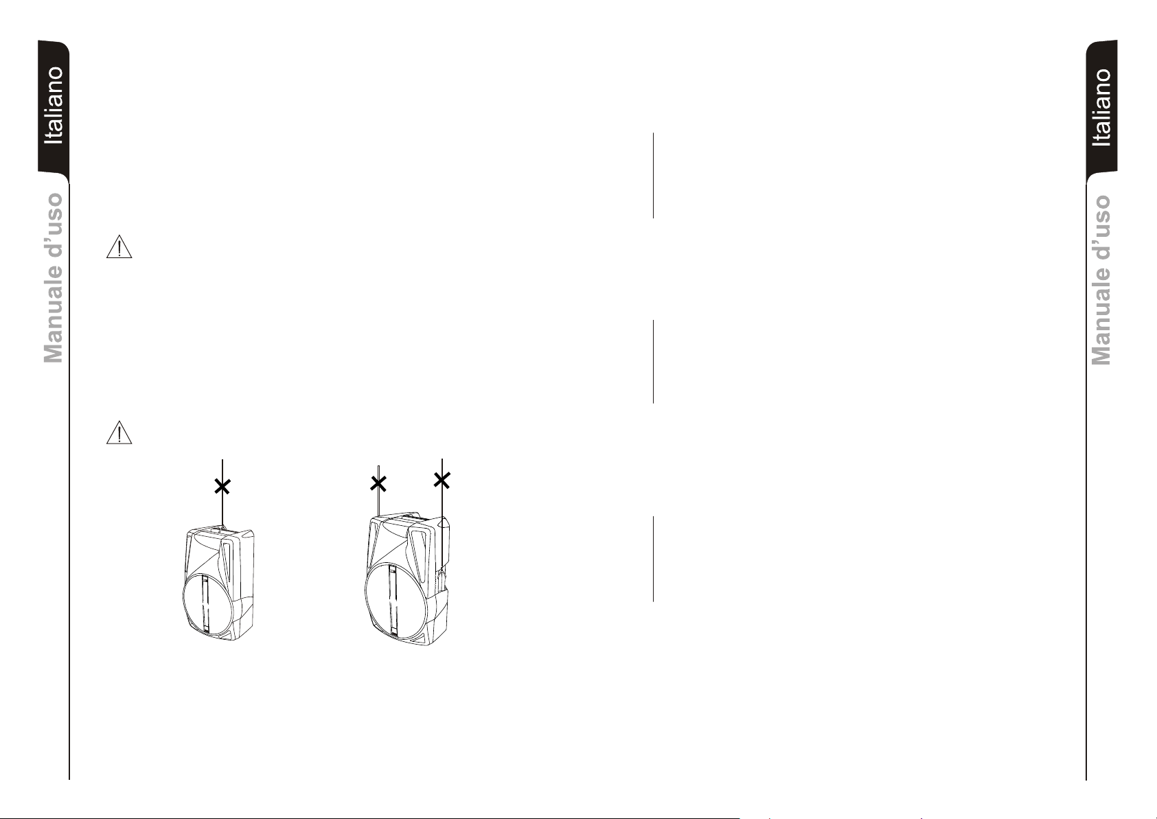
Per evitare condizioni di pericolo non sovrapporre fra loro più diffusori senza adeguati
sistemi di ancoraggio. Prima si sospendere il diffusore controllare tutti i componenti da
utilizzare, che non devono presentare danni, deformazioni, parti mancanti o danneggiate
che possono ridurre la sicurezza dell’installazione.
Nell’utilizzo all’aperto evitare luoghi esposti alle intemperie.
Il diffusore viene fornito dalla ditta costruttrice predisposto per l’utilizzo :
Manuale d’usoManuale d’uso
- in appoggio (FIG. 1)
- a pavimento (come monitor) (Fig.2)
- su supporto piantana (FIG.3)
- appeso con apposita staffa fornita dalla ditta (FIG.4)
ATTENZIONE
Non utilizzare mai le maniglie per appendere il diffusore!
ItalianoItalianoItaliano
Manuale d’usoManuale d’uso
O
RPEAORP EA
OP
OP
ER
ER
A
A
D
D
d
d
d
d
d
d
B
B
B
B
B
B
TO
TO
T
T
T
T
EHI
EHI
E
E
E
E
C
C
C
C
H
H
H
H
N
N
N
N
N
N
O
O
O
O
L
L
L
L
L
L
O
O
O
O
O
O
G
G
G
G
I
I
I
I
E
E
E
E
E
E
SCG
SCG
S
S
S
S
9
D D
OPERA 208 D OPERA 210D OPERA 410 D
dd
dd
dd
BB
BB
BB
T
T
T
T
T
T
EC
EC
E
E
E
E
C
C
C
C
HO
HO
HI
HI
HI
HI
N
N
N
N
N
N
O
O
O
O
O
O
L
L
L
L
L
L
O
O
O
O
G
G
G
G
G
G
I
I
E
E
ES
ES
ES
ES
S
S
DATI TECNICI
Amplificatore e processore
Tipo alimentazione: Analogica Analogica SMPS
Tipo di amplificatore HF: Classe-D 50 W/RMS Classe-D 50 W/RMS Classe-D 100 W/RMS
Tipo di amplificatore BF: Classe-D 150 W/RMS Classe-D 150 W/RMS Classe-D 300 W/RMS
Ventilazione: Convenzione, No ventola Convenzione, No ventola Convenzione, No ventola
Predisposiyione del sistema: Flat, Processed Flat, Processed Flat, Processed
Controlli/limitazioni: Picco,RMS, Temico, Limiti Picco,RMS, Temico, Limiti Picco,RMS, Temico, Limiti
Pre-Amplificatore: 24bit 48KHz DSP 24bit 48KHz DSP 24bit 48KHz DSP
Frequenza X-over (taglio): 2050 Hz, 24 dB/oct. 2050 Hz, 24 dB/ oct. 1940 Hz, 24 dB/ oct
Dati Audio
Risposta in frequenza -10 dB: 67 Hz - 20 kHz 62 Hz - 20 kHz 61 Hz - 20 kHz
Risposta in frequenza +-3 dB: 78 Hz - 19 kHz 71 Hz - 19 kHz 70 Hz - 19 kHz
SPL massimo: 121 dB 122 dB 127 dB
Woofer: 1x8“ - 1,5“ voice coil 1x10“ - 1,5“ voice coil 1x10 - 2“ voice coil
Driver: 1x1“ driver Neodimio 1x1“ driver Neodimio 1x1“ Compression driver 1,3” voice coil
Tromba (driver): 80°/65 x 60° 80°/65 x 60° 80°/65 x 60°
XLR maschio Bilanciato XLR maschio Bilanciato XLR maschio Bilanciato
6,3mm JACKBilanciato 6,3mm JACK Bilanciato 6,3mm JACK Bilanciato
Sezione ingressi
Ingressi/link: XLR femmina Bilanciato XLR femmina Bilanciato XLR femmina Bilanciato
Sensibilitä in ingresso: -40dBu/-3dBu (Mic/Line) -40dBu/-3dBu (Mic/Line) -40dBu/-3dBu (Mic/Line)l
Alimentazione: IEC, VDE IEC, VDE IEC, VDE
Equipaggiamento meccanico
Supporto piantana: 36 mm 36mm 36mm
Maniglie: una superiore una superiore (in gomma) una superiore (in gomma)
Angolo appoggio: 43° per monitor 43° per monitor 43° per monitor
Rete forntale: 1,2mmm Metallica con foam 1,2mmm Metallica con foam 1,2mmm Metallica con foam
Dimensione (L x H x P): 300 x 484 x 284 mm 343 x 553 x 304 mm 343 x 553 x 304 mm
Peso: 8,4 kg 9,8 kg 10,6 kg
Accessori opzionali: Custodia, Staffa a muro Custodia, Staffa a muro Custodia, Staffa a muro
10
Page 7

ItalianoItalianoItaliano
ItalianoItalianoItaliano
Manuale d’usoManuale d’uso
Manuale d’usoManuale d’uso
OPERA602D OPERA 605 D
XLR maschio Bilanciato XLR maschio Bilanciato
OPERA 402 D OPERA 405 D
6,3mm JACK Bilanciato 6,3mm JACK Bilanciato
due laterali (in gomma) due laterali (in gomma)
1,75“ voice coil Neodimio 1,75“ voice coil Neodimio
XLR maschio Bilanciato XLR maschio Bilanciato
6,3mm JACKBilanciato 6,3mm JACK Bilanciato
due laterali (in gomma) due laterali (in gomma)
11
DATI TECNICI
Amplificatore e processore
Tipo alimentazione: SMPS SMPS
Tipo di amplificatore HF: Class-D 200 W/RMS Class-D 200 W/RMS
Tipo di amplificatore BF: Class-D 400 W/RMS Class-D 400 W/RMS
Ventilazione: Convenzione, No ventola Convenzione, No ventola
Predisposizione del sistema: Flat, Processed Flat, Processed
Controlli/limitazioni: Picco,RMS, Temico, Limiti Picco,RMS, Temico, Limiti
Pre-Amplificatore: 24bit 48KHz DSP 24bit 48KHz DSP
Frequenza X-over (taglio): 1690 Hz, 24 dB/oct. 1670 Hz, 24 dB/ oct.
Dati Audio
Risposta in frequenza -10 dB: 58 Hz - 20 kHz 48 Hz - 20 kHz
Risposta in frequenza +-3 dB: 68 Hz - 19 kHz 59 Hz - 19 kHz
SPL massimo: 129 dB 130 dB
Woofer: 1x12“ - 3“ voice coil Neodimio 1x15“ - 3“ voice coil Neodinio
Driver: 1x1“ compression driver (RCF ND350) 1x1“ compression driver (RCF ND350)
Tromba (driver): 80°/65 x 60° 80°/65 x 60°
Input section
Ingressi/link: XLR femmina Bilanciato XLRfemmina Bilanciato
Sensibilitä in ingresso: -40dBu/-3dBu (Mic/Line) -40dBu/-3dBu (Mic/Line)
Alimentazione: IEC, VDE IEC, VDE
Equipaggiamento meccanico
Supporto piantana: 36 mm 36mm
Maniglie: una superiore (in gomma) una superiore (in gomma)
Angolo appoggio: 43° for monitor 43° for monitor
Rete frontale: 1,5mmm Metallica with foam 1,5mmm Metallica with foam
Dimensione (Lx H x P): 432 x 655 x 353mm 432 x 655 x 353mm
DATI TECNICI
Amplificatore e processore
Tipo alimentazione: SMPS SMPS
Tipo di amplificatore HF: Class-D 100 W/RMS Class-D 100 W/RMS
Tipo di amplificatore BF: Class-D 300 W/RMS Class-D 300 W/RMS
Ventilazione: Convenzione, No ventola Convenzione, No ventola
Predisposizione del sistema: Flat, Processed Flat, Processed
Controlli/limitazioni: Picco,RMS, Temico, Limiti Picco,RMS, Temico, Limiti
Pre-Amplificatore: 24bit 48KHz DSP 24bit 48KHz DSP
Frequenza X-over (taglio): 1870Hz, 24 dB/oct. 1850 Hz, 24 dB/ oct.
Dati Audio
Risposta in frequenza -10 dB: 59 Hz - 20 kHz 49 Hz - 20 kHz
Risposta in frequenza +-3 dB: 70 Hz - 19 kHz 58 Hz - 19 kHz
SPL massimo: 128 dB 129 dB
Woofer: 1x12“ - 2“ voice coil 1x15“ - 2“ voice coil
Driver: 1x1“ compression driver - 1,5” voice coil 1x1“ compression driver - 1,5” voice coil
Tromba (driver): 80°/65 x 60° 80°/65 x 60°
Sezione ingressi
Ingressi/link: XLR femmina Bilanciato XLR femmina Bilanciato
Sensibilitä in ingresso: -40dBu/-3dBu (Mic/Line) -40dBu/-3dBu (Mic/Line)
Alimentazione: IEC, VDE IEC, VDE
Equipaggiamento meccanico
Supporto piantana: 36 mm 36mm
Maniglie: una superiore (in gomma) una superiore (in gomma)
Angolo appoggio: 43° per monitor 43° per monitor
Rete forntale: 1,5mmm Metallica con foam 1,5mmm Metallica con foam
Dimensione (L x H x P): 432 x 655 x 353mm 432 x 655 x 353mm
Peso: 14,1 kg 14,5 kg
Accessori opzionali: Custodia, Staffa a muro Custodia, Staffa a muro
Peso: 12,4 kg 12,9 kg
12
Accessori opzionali: Custodia, Staffa a muro Custodia, Staffa a muro
Page 8
13
IMPORTANT SAFETY INSTRUCTIONS
CAUTION: TO REDUCE THE RISK OF ELECTRICAL
WARNING: TO REDUCE THE RISK OF FIRE OR
EnglishEnglishEnglish
SHOCK, DO NOT REMOVE THE COVER
(OR BACK). NO USER SERVICEABLE
PARTS INSIDE; REFER SERVICING TO
QUALIFIED PERSONNEL.
ELECTRICAL SHOCK. DO NOT
EXPOSE THIS APPLIANCE TO RAIN OR
MOISTURE.
This symbol, wherever it appears, alerts you to the presence of uninsulated dangerous
voltage inside the enclosure - voltage that may be sufficient to constitute a risk of shock.
This symbol wherever it appears, alerts you to important operating and maintenance
instructions in the accompanying literature. Read the manual.
IMPORTANT NOTES
This manual is to be considered an integral part of the product, and must always accompany the
equipment when it changes ownership, as a reference for correct installation and operation as well as
for the safety regulations. The Manufacturing company will not assume any responsibility for incorrect
installation of the amplifier.
user manualuser manual
Read these instructions
All the safety and operation instructions should be read before the appliance is operated.
Heed all Warnings
All warnings on the appliance and in the operating instructions should be adhered to
Long period non use of equipment
If long term non use of appliance is expected, it would be better to unplug this apparatus from power
supply, put it into proper packaging and cover to avoid dust exposure.
Damage and repair
If apparatus has been damaged it is forbidden to repair it or to remove cover. Disconnect the unit from
the mains power and contact technical assistance for repair.
INSTALLATION AND OPERATING PRECAUTIONS
GENERAL
Keep these instructions
For a correct use of the appliance, the safety and operating instructions should be retained for future
reference.
Apparatus positioning
Make sure that the apparatus is positioned in a stable and secure way in order to avoid any dangerous
conditions for persons or objects.
Grounding protection
The apparatus is made in protection CLASS I to prevent the risk of electrical shock the appliance must
be connected to a mains socket outlet with a protective earthing connection. Before making the
electrical connection of the appliance, ensure that the electrical distribution network conforms to the
regulations regarding electrical equipment.
Power Source
The appliance should be connected to a power supply only of the type described in the operating
instructions or as marked on the appliance (see “Specifications”). In order not to jeopardize the safety
of the amplifier, it must only be connected to the mains using the power cable provided.
Power Cord Protection
To ensure a safe use of appliance, use only the power cord supplied with the equipment, taking care to
place it and protect it to avoid damage during use. If power cord becomes damaged contact technical
assistance and request replacement. Do not use cables other than supplied cables.
Water and Moisture
Do not install this apparatus near water (e.g. near washbasins, sinks, showers, bathtubs, swimming
pool, wet floors or anything in the presence of water and liquids in general).
“CAUTION”
TO PREVENT ELECTRICAL SHOCK
DO NOT REMOVE COVER
“AVIS”
RISQUE DE CHOCH ELECTRIQUE
NE PAS OUVRIR
Object and Liquid Entry
The apparatus must be placed in inappropriate position. Care should be taken so that objects do not
fall and liquids are not spilled into the enclosure through cooling grid with consequent electrical
danger.
Ventilation
The appliance should be situated so that its location or position does not interfere with its proper
ventilation. Do not block or cover any openings of the grid ventilation or heatsink. Install the apparatus
at a distance that ensures a good ventilation between devices.
Heat
Do not install the appliance near any source of heat.
Accessories and installation
For a safe installation, do not make any holes in the external chassis for the application of additional
brackets. In case of particular installations not described in this manual, contact technical service for
accessories specified by the manufacturer.
Follow the instructions
All operations and instructions in this user manual should be followed for a correct operation and
function of appliance. Pay attention in particular to:
- Never force the control elements (switches, controls, etc.).
- Do not force the amplifier to work in overload for extended periods of time.
Cleaning
Clean only with a dry cloth. Do not use solvents, alcohol, benzene or volatile substances for cleaning
the exterior parts.
CONNECTION
CAUTION
- For connecting the appliance, use only qualified and experienced personnel having sufficient
technical knowledge or specific instructions for making the connections correctly and thus
preventing electrical dangers.
- To prevent the risk of electrical shock, the appliance must only be supplied from the mains after
all connections have been completed.
- Before powering up the appliance, it is advisable to re-check all the connections.
- The entire sound system must be designed and installed in compliance with the current
standards and regulations regarding electrical systems.
SUGGESTIONS
CAUTION
To prevent inductive phenomena from giving rise to hum or disturbance which would jeopardize
efficient appliance operation, the cables that transmit microphone signals or line level signals (e.g. 0
dB/V) must be screened and should not be run in the vicinity of:
1) Equipment that produces strong magnetic fields (e.g. large power supply transformers)
2) Electrical energy conductors
3) Lines that supply speakers.
This device complies with European Directives 2006/95/EC and 2004/108/EC and is provided with
CE marking.
The respective declaration of conformity is available in AEB Industriale s.r.l.
EMI CLASSIFICATION
According to the standards EN 55103 this equipment is designed and suitable to operate in E3 (or
lower E2, E1) Electromagnetic environments.
EnglishEnglishEnglish
user manualuser manual
14
Page 9

user manualuser manual
EnglishEnglishEnglish
DESCRIPTION
The models of the “OPERA D” series use cutting edge digital amplifiers of the DIGIPRO
series, providing three different powers - 200W, 400W, and 600W - to meet the
requirements of any kind of application.
These highly efficient amplifiers provide high power with limited weight and dimension.
Thanks to the low power dissipated, the cooling of the amplifier module does not require a
fan.
The digital preamplifier with DSP (Digital Signal Processing) controls the audio crossover
of the acoustic components, the frequency response, the limiter, and the phase
alignment. A selector enables to select one of two different equalizations - “FLAT” or
“PROCESSED“ - to provide high versatility for the different applications.
The amplifiers DIGIPRO 400W e 600W use power supplies featuring SMPS (Switched-
®
Mode Power Supplies) technology.
This technology increases power supply efficiency and minimizes its weight.
The correct operation is signalled by the lighting of a blue indicator, located on the front
panel of the speaker. The indicator can be disabled following a specific procedure
described in paragraph “Front LED” (Page 20).
OPERA 208D
The OPERA 208D bi-amped active speaker is
equipped with a DIGIPRO amplifier delivering 150W
®
RMS for the bass section and 50W RMS for the high
frequency section.
The 2-way bi-amplified speaker is equipped with 8”
woofer (1,5” voice coil) and 1” Neodymium driver (1”
voice coil) loaded with 80°/65°x60° asymmetric horn.
The speaker is in plastic material, provided with
recessed top handle, easing its transport.
In the bottom of the box there is a standard pole mount
cup (D36mm).
The speaker has been designed to be used also as
O
O
P
P
E
E
R
R
A
A
D
D
stage monitor (43° angle).
®
OPERA 210D
The OPERA 210D bi-amped active speaker is
equipped with a DIGIPRO amplifier delivering 150W
®
RMS for the bass section and 50W RMS for the high
frequency section.
The 2-way bi-amplified speaker is equipped with 10”
woofer (1,5” voice coil) and 1” Neodymium driver (1”
voice coil) loaded with 80°/65°x60°asymmetric horn.
EnglishEnglishEnglish
The speaker is plastic material and is provided with
top handle, rubber coated , easing its transport
In the bottom of the box there is a standard pole mount
cup (D36mm).
The speaker has been designed to be used also as
stage monitor (43° angle).
OPERAOPERA
D D
OPERA 410D
The OPERA 410D bi-amped active speaker is
equipped with a DIGIPRO amplifier delivering 300W
®
RMS for the bass section and 100W RMS for the high
frequency section.
d
d
dd
d
The 2-way bi-amplified speaker is equipped with 10”
woofer (2” voice coil) and 1” compression driver (1.3”
d
B
B
BB
B
B
T
T
T
T
T
T
EH
EH
E
E
E
E
C
C
C
C
C
C
H
H
H
H
N
N
N
N
N
N
O
O
O
O
O
O
L
L
L
L
L
L
O
O
O
O
O
O
G
G
G
G
G
G
I
I
I
I
I
I
E
E
E
E
E
E
S
S
S
S
S
S
voice coil) loaded with 80°/65°x60° asymmetric horn.
The speaker is plastic material and is provided with
user manualuser manual
top handle, rubber coated , easing its transport
In the bottom of the box there is a standard pole mount
cup (D36mm).
The speaker has been designed to be used also as
stage monitor (43° angle).
15
DRIVER
INDICATOR
LIGHT
WOOFER
REFLEX HOLES
REFLEX HOLES
AMPLIFIER
43° PLANE
dd
d
d
dd
BB
B
B
BB
T
T
T
T
T
T
EH
EH
E
E
E
E
C
C
C
C
C
C
H
H
H
H
N
N
N
N
N
N
O
O
O
O
O
O
L
L
L
L
L
L
O
O
O
O
O
O
G
G
G
G
G
G
I
I
I
I
I
I
E
E
E
E
E
E
S
S
S
S
S
S
HANDLE
OPERA
D
43° PLANE
TECHNOLOGIES
d
B
II
Æ 36mm PEDESTAL/BRACKET
HOUSING
DRIVER
INDICATOR
LIGHT
WOOFER
REFLEX HOLES
REFLEX HOLES
AMPLIFIER
43° PLANE
HANDLE
OPERA
D
43° PLANE
TECHNOLOGIES
d
B
II
Æ 36mm PEDESTAL/BRACKET
HOUSING
16
Page 10

user manualuser manual
EnglishEnglishEnglish
OPERA 402D
The OPERA 402D bi-amped active speaker is
equipped with a DIGIPRO amplifier delivering 300W
®
RMS for the bass section and 100W RMS for the high
frequency section.
The 2-way bi-amplified speaker is equipped with 12”
woofer (2” voice coil) and 1” compression driver (1.5”
voice coil) loaded with 80°/65°x60°asymmetric horn.
The speaker is plastic material and is provided with
top handle and two rubber coated side handles,
easing its transport.
In the bottom of the box there is a standard pole
mount cup (D36mm).
The speaker has been designed to be used also as
stage monitor (43° angle).
OPERA 405D
The OPERA 405D bi-amped active speaker is
equipped with a DIGIPRO amplifier delivering 300W
®
RMS for the bass section and 100W RMS for the high
frequency section.
The 2-way bi-amplified speaker is equipped with 15”
woofer (2” voice coil) and 1” compression driver (1.5”
voice coil) loaded with 80°/65°x60°asymmetric horn.
The speaker is plastic material and is provided with
top handle and two rubber coated side handles,
easing its transport.
In the bottom of the box there is a standard pole
mount cup (D36mm).
The speaker has been designed to be used also as
stage monitor (43° angle).
OPERA 602D
The OPERA 602D bi-amped active speaker is
equipped with a DIGIPRO amplifier delivering 400W
®
RMS for the bass section and 200W RMS for the high
frequency section.
The 2-way bi-amplified speaker is equipped with 12”
Neodimio woofer (3” voice coil) and 1” compression
driver (1.75” voice coil) loaded with 80°/65°x60°
asymmetric horn.
EnglishEnglishEnglish
The speaker is plastic material and is provided with
top handle and two rubber coated side handles,
easing its transport.
In the bottom of the box there is a standard pole
mount cup (D36mm).
OPE
RA
RAOPE
D D
The speaker has been designed to be used also as
stage monitor (43° angle).
OER
OER
P A
P A
DD
OPERA 605D
The OPERA 605D bi-amped active speaker is
equipped with a DIGIPRO amplifier delivering 400W
dd
dd
dd
BB
BB
BB
T
T
TEH
TEH
TEH
TEH
E
E
C
C
C O
C O
C O
C O
H
H
N
N
N
N
N
N
OL
OL
O
O
O
O
L S
L S
L S
L S
O
O
G
G
G
G
G
G
IS
IS
I
I
I
I
E
E
E
E
E
E
RMS for the bass section and 200W RMS for the high
frequency section.
The 2-way bi-amplified speaker is equipped with 15”
®
dd
dd
dd
BB
BB
BB
TH
TH
TE
TE
TE
TE
E
E
C
C
C O
C O
C O
C O
H
H
H
H
N
N
N
N
N
N
O
O
O
O
O
O
L
L
L S
L S
L S
L S
O
O
G
G
G
G
G
G
I
I
I
I
I
I
E
E
E
E
E
E
S
S
user manualuser manual
Neodimio woofer (3” voice coil) and 1” compression
driver (1.75” voice coil) loaded with
80°/65°x60°asymmetric horn.
The speaker is plastic material and is provided with
top handle and two rubber coated side handles,
easing its transport.
In the bottom of the box there is a standard pole
mount cup (D36mm).
The speaker has been designed to be used also as
stage monitor (43° angle).
17
DRIVER
INDICATOR
LIGHT
WOOFER
REFLEX HOLES
REFLEX HOLES
AMPLIFIER
43° PLANE
HANDLE
OPERA
D
TECHNOLOGIES
d
B
II
HANDLEHANDLE
43° PLANE
Æ 36mm PEDESTAL/BRACKET
HOUSING
DRIVER
INDICATOR
LIGHT
WOOFER
REFLEX HOLES
REFLEX HOLES
AMPLIFIER
43° PLANE
HANDLE
OPERA
D
TECHNOLOGIES
d
B
II
HANDLEHANDLE
43° PLANE
Æ 36mm PEDESTAL/BRACKET
HOUSING
18
Page 11

COMMANDS AND FUNCTIONS
AMPLIFIER PANEL
1) “Balenced Input” - “Link” - “Input Link” CONNECTORS
These balanced inputs can be used to connect balanced or unbalanced
microphones or audio sources at line level (0dB) (eg. preamplifier, mixer, recorder,
CD player, musical instrument, ...).
EnglishEnglishEnglish
user manualuser manual
The balanced connector is connected in parallel and can be used to send the audio
signal to other amplified speakers, recorders or supplementary amplifiers.
2) “Limiter” INDICATOR LIGHT
This indicator shows red to indicate that the internal limiter circuit has tripped.
This prevents amplifier distortion and protects the speakers against overloads.
3) “Signal” INDICATOR LIGHT
This indicator shows green to indicate the presence of the audio signal (at a level of 20dB).
4) “Ready” INDICATOR LIGHT
This indicator shows green to indicate that the main power voltage is correct.
The LED shows green normal operating conditions
5) “Sensitivity” INPUT SENSITIVITY CONTROL
This control adjusts the sensitivity of the signal amplifier input.
This control does not affect the “Link” - “Input - Link” output level
6) MODE SWITCH
This two-way switch allows to choose between two different system presets.
The “Flat” position allows linear response of the speaker, which is mainly suitable for
the “live” application.
The “Processed” position emphasizes the low frequency and regulates the mid
frequency. It is suitable for music play back
7) “Input Sens” SWITCH
Position the switch in LINE to use a line level source (0 dB) or MIC to use a
microphone.
8) POWER CABLE SOCKET “MAINS”
Used for connecting the power cable supplied.
9) FUSE CARRIER “FUSE”
Mains fuse housing.
10) POWER SWITCH “POWER”
This switch can be used to switch the diffuser on and off.
SPEAKER FRONT
1) INDICATOR LIGHT
The blue indicator light indicates speaker status
CHARACTERISTICS AND PROTECTION
Front Grille
The speakers’s components in the box are protected by 1.2mm metal steel grille
version) (10”,12” and 15” versions)
and by 1.5mm metal steel grille covered by foam on
backside.
Cooling
Thermal control is provided by the internal microprocessor which, by means of two
sensors, controls the temperature of the amplifier and of the power supply, avoiding
overheating by limiting the overall volume.
In case of overheating (> 80 degrees) the volume decreases proportionally to the
temperature increase, making the change unnoticeable.
The correct volume and all the functions are automatically restored when standard
operating temperatures are reached.
Front LED
On the front of the speaker a blue LED indicates the state of the speaker.
During normal operation the speaker front LED can be disabled if necessary (theatre,
cinema installations)
To change the state of the front LED, press and release for several times (6 times) the
MODE switch during switch on, when all the LEDs ( Limiter , Signal and Ready ) on the
amplifier module are off.
To restore front LED operation, repeat the operation.
The diagnostics of the speaker provided by this LED, is still active even if the LED is
disabled.
Switch on
The amplifiers are equipped with a microprocessor to control the DSP and the amplifier.
The correct switch on of the amplifier is ensured by an initialization procedure; during this
test stage, the blue front LED flashes twice and the LEDs ( Limiter , Signal and Ready ),
located on the amplifier module, remain off for approx. 2 sec.
At the end of the switch on procedure, the front LED lights up (if enabled) and on the
amplifier module the Ready green LED only remains steadily on.
In case of severe failure of the speaker, the LED on the front panel flashes several times
and on the amplifier module, the Limiter red LED flashes.
The speaker switches to “mute”.
Failure indications and safeties
The microprocessor is able to signal three different kinds of failure by flashing the “Limter”
red LED on the amplifier panel before the lighting up of the “Ready” green LED. The three
types of failure are:
1) WARNING: a non severe error or auto-ripristinate malfunction is detected and the
performance of the speaker is not limited
2) LIMITATION: an error is detected and the performance of the speaker is limited (the
sound level is reduced by 3dB).
This does not affect the operation of the speaker since it continues to operate.
However, it is necessary to call the service centre to solve the issue.
3) FAILURE: a severe malfunction is detected. The speaker switches to “mute”.
“”
“”
“”“” “”
“”“” “”
(8”
EnglishEnglishEnglish
user manualuser manual
19
Flashing Indication
1 or 2 Warning
3 or 4 Limitation
from 5 to 8 Failure
In case of failure, the “Ready” green LED remains off.
20
Page 12

Perform the checks listed below:
- Check if the speaker is properly connected to the power supply.
- Make sure that the power supply is of correct voltage.
- Check that the amplifier is not overheated.
- Disconnect the speaker from the mains power supply, wait for a few minutes and
connect it again.
If after these tests the red “LIMITER” LED is still on, please contact an authorised service
EnglishEnglishEnglish
centre.
LOUDSPEAKER INSTALLATION
WARNING
Make sure that the loudspeaker is securely installed in a stable position to avoid any
injuries or damages to persons or property.
For safety reasons do not place one loudspeaker on top of another without proper
fastening systems. Before hanging the loudspeaker check all the components for
damages, deformations, missing or damaged parts that may compromise safety during
installation.
If you use the loudspeakers outdoors avoid places that are exposed to bad weather.
The loudspeaker has the following mounting options:
user manualuser manual
- bookshelf (Fig. 1)
- floor (monitor) (Fig.2)
- on speaker stands (Fig.3)
- suspended with brackets supplied by the manufacturer (Fig.4)
EnglishEnglishEnglish
user manualuser manual
21
WARNING
Never use the handles to hang the speaker!
OPER
OPER
A
A
D
D
d
d
d
d
d
d
B
B
B
B
B
B
TO
TO
T
T
T
T
EHI E
EHI E
E
E
E
E
C
C
C
C
H
H
H
H
N
N
N
N
N
N
O
O
O
O
L
L
L
L
L
L
O
O
O
O
O
O
G
G
G
G
I
I
I
I
E
E
E
E
SCG
SCG
S
S
S
S
OPE A
OPE AR
R
DD
d
d
d
dd
d
B
B
B
BB
B
T
T
T
T
T
T
EC
EC
E
E
E
E
C
C
C
C
H
H
HL
HL
HL
HL
N E
N E
N
N
N
N
O
O
OG
OG
OG
OG
L
L
OI
OI
O
O
O
O
G
G
I
I
I
I
E
E
E
E
S
S
S
S
S
S
OPERA 208 D OPERA 210D OPERA 410 D
TECHNICAL SPECIFICATIONS
Amp and processor
Power supply: Analog Analog SMPS
HF amp: Class-D 50 W/RMS Class-D 50 W/RMS Class-D 100 W/RMS
Bass amp: Class-D 150 W/RMS Class-D 150 W/RMS Class-D 300 W/RMS
Cooling: Convection, fan-free Convection, fan-free Convection, fan-free
System presets: Flat, Processed Flat, Processed Flat, Processed
Limiter: Peak,RMS, Thermal, limiters Peak,RMS, Thermal, limiters Peak,RMS, Thermal, limiters
Pre-Amp: 24bit 48KHz DSP 24bit 48KHz DSP 24bit 48KHz DSP
X-over frequency: 2050 Hz, 24 dB/oct. 2050 Hz, 24 dB/ oct. 1940 Hz, 24 dB/ oct
Audio Data
Frequency response -10 dB: 67 Hz - 20 kHz 62 Hz - 20 kHz 61 Hz - 20 kHz
Frequency response +-3 dB: 78 Hz - 19 kHz 71 Hz - 19 kHz 70 Hz - 19 kHz
Max SPL: 121 dB 122 dB 127 dB
Bass/midrange woofer: 1x8“ - 1,5“ voice coil 1x10“ - 1,5“ voice coil 1x10 - 2“ voice coil
High frequency driver: 1x1“ driver Neodymium 1x1“ driver Neodymium 1x1“ Compression driver 1,3” voice coil
Horn: 80°/65 x 60° CD Horn 80°/65 x 60° CD Horn 80°/65 x 60° CD Horn
XLR male balanced XLR male balanced XLR male balanced
6,3mm JACK balanced 6,3mm JACK balanced 6,3mm JACK balanced
Input section
Signal input/link: XLR fem. Balanced XLR fem. Balanced XLR fem. Balanced
Input sensitivity: -40dBu/-3dBu (Mic/Line) -40dBu/-3dBu (Mic/Line) -40dBu/-3dBu (Mic/Line)
Mains: IEC, VDE IEC, VDE IEC, VDE
Hardware
Pole mount: 36 mm 36mm 36mm
Handles: one on top one on top (rubber) one on top (rubber)
Angles up: 43° for monitor 43° for monitor 43° for monitor
Grille: 1,2mmm Metal with foam 1,5mmm Metal with foam 1,5mmm Metal with foam
Dimensions (W x H x D): 300 x 484 x 284 mm 343 x 553 x 304 mm 343 x 553 x 304 mm
Weight: 8,4 kg 9,8 kg 10,6 kg
Optional accessories: gig bag, mounting bracket gig bag, mounting bracket gig bag, mounting bracket
22
Page 13

EnglishEnglishEnglish
EnglishEnglishEnglish
user manualuser manual
XLR male balanced XLR male balanced
6,3mm JACK balanced 6,3mm JACK balanced
OPERA 402 D OPERA 405 D
One on top (with rubber) one on top (with rubber)
OPERA 602 D OPERA 605 D
1,75“ voice coil Neodymium 1,75“ voice coil Neodymium
XLR male balanced XLR male balanced
6,3mm JACK balanced 6,3mm JACK balanced
one on top (with rubber) one on top (with rubber)
user manualuser manual
23
TECHNICAL SPECIFICATION
Amp and processor
Power supply: SMPS SMPS
HF amp: Class-D 200 W/RMS Class-D 200 W/RMS
Bass amp: Class-D 400 W/RMS Class-D 400 W/RMS
Cooling: Convection, fan-free Convection, fan-free
System presets: Flat, Processed Flat, Processed
Limiter: Peak,RMS, Thermal, limiters Peak,RMS, Thermal, limiters
Pre-Amp: 24bit 48KHz DSP 24bit 48KHz DSP
X-over frequency: 1690 Hz, 24 dB/oct. 1670 Hz, 24 dB/ oct.
Audio Data
Frequency response -10 dB: 58 Hz - 20 kHz 48 Hz - 20 kHz
Frequency response +-3 dB: 68 Hz - 19 kHz 59 Hz - 19 kHz
Max SPL: 129 dB 130 dB
Bass/midrange woofer: 1x12“ - 3“ voice coil Neodymium 1x15“ - 3“ voice coil Neodymium
High frequency driver: 1x1“ compression driver (RCF ND350) 1x1“ compression driver (RCF Nd350) Neodymium
Horn: 80°/65 x 60° CD Horn 80°/65 x 60° CD Horn
Input section
Signal input/link: XLR fem. Balanced XLR fem. Balanced
Input sensitivity: -40dBu/-3dBu (Mic/Line) -40dBu/-3dBu (Mic/Line)
Mains: IEC, VDE IEC, VDE
Hardware
Pole mount: 36 mm 36mm
Handles (rubber): two on side (with rubber) two on side (with rubber)
Angles up: 43° for monitor 43° for monitor
Grille: 1,5mmm Metal with foam 1,5mmm Metal with foam
Dimensions (W x H x D): 432 x 655 x 353mm 432 x 655 x 353mm
TECHNICAL SPECIFICATION
Amp and processor
Power supply: SMPS SMPS
HF amp: Class-D 100 W/RMS Class-D 100 W/RMS
Bass amp: Class-D 300 W/RMS Class-D 300 W/RMS
Cooling: Convection, fan-free Convection, fan-free
System presets: Flat, Processed Flat, Processed
Limiter: Peak,RMS, Thermal, limiters Peak,RMS, Thermal, limiters
Pre-Amp: 24bit 48KHz DSP 24bit 48KHz DSP
X-over frequency: 1870Hz, 24 dB/oct. 1850 Hz, 24 dB/ oct.
Audio Data
Frequency response -10 dB: 59 Hz - 20 kHz 49 Hz - 20 kHz
Frequency response +-3 dB: 70 Hz - 19 kHz 58 Hz - 19 kHz
Max SPL: 128 dB 129 dB
Bass/midrange woofer: 1x12“ - 2“ voice coil 1x15“ - 2“ voice coil
High frequency driver: 1x1“ compression driver - 1,5” voice coil 1x1“ compression driver - 1,5” voice coil
Horn: 80°/65 x 60° CD Horn 80°/65 x 60° CD Horn
Input section
Signal input/link: XLR fem. Balanced XLR fem. Balanced
Input sensitivity: -40dBu/-3dBu (Mic/Line) -40dBu/-3dBu (Mic/Line)
Mains: IEC, VDE IEC, VDE
Hardware
Pole mount: 36 mm 36mm
Handles: two on side (with rubber) two on side (with rubber)
Angles up: 43° for monitor 43° for monitor
Grille: 1,5mmm Metallica with foam 1,5mmm Metallica with foam
Dimensions (W x H x D): 432 x 655 x 353mm 432 x 655 x 353mm
Weight: 14,1 kg 14,5 kg
Optional accessories: gig bag, mounting bracket gig bag, mounting bracket
Weight: 12,4 kg 12,9 kg
24
Optional accessories: gig bag, mounting bracket gig bag, mounting bracket
Page 14

25
SICHERHEITSHINWEISE
WARNUNG: UM STROMSCHLAGGEFAHR ZU
DeutschDeutschDeutsch
BedienungsanleitungBedienungsanleitung
ACHTUNG: UM BRAND- UND STROMSCHLAGGEFAHR
WICHTIG
Dieses Handbuch ist wesentlicher Bestandteil des Geräts und muss dieses auch bei Besitzerwechsel
begleiten, damit der neue Besitzer die Installations- und Gebrauchshinweise sowie die
Sicherheitshinweise kennt.
Die nicht mit den in diesem Handbuch enthaltenen Vorschriften und Modalitäten übereinstimmende
Installation und Verwendung entheben den Hersteller jeder Haftung für Personen-, Sach- und
Anlagenschäden.
Die folgenden Anweisungen lesen
Alle Sicherheits- und Betriebsanweisungen müssen vor der Inbetriebnahme des Geräts gelesen und
verstanden werden.
Alle Warnhinweise berücksichtigen
Alle Warnhinweise für das Gerät und die Betriebsanweisungen müssen getreu befolgt werden.
Längere Nichtbenutzung des Geräts
Wenn eine längere Nichtbenutzung des Geräts abzusehen ist, sollten Sie es vom Versorgungsnetz
abtrennen, es erneut in die entsprechende Verpackung legen oder es so zudecken, dass eine
Staubaussetzung vermieden wird.
Störfälle und Reparaturen
Bei Gerätestörfall ist es dem Benutzer strengstens untersagt, eine Reparatur zu versuchen bzw. den
Schutzdeckel zu entfernen. Das Gerät vom Versorgungsnetz abtrennen und für eine Reparatur mit dem
Kundendienst Kontakt aufnehmen.
VORSICHTSMASSNAHMEN FÜR INSTALLATION UND GEBRAUCH
ALLGEMEINES
Die Anleitungen aufbewahren
Für den korrekten Gebrauch des Geräts muss dieses Handbuch für alle zukünftigen Einsichtnahmen
sorgfältig erhalten werden.
Positionierung des Geräts
Das Gerät in einer stabilen und sicheren Position aufstellen, damit gefährliche Situationen für
Gegenstände, Personen und Anlagen vermieden werden.
Schutzerdung
Das Gerät wurde mit Schutzklasse 1 für den elektrischen Schlag hergestellt und der Anschluss an das
Versorgungsnetz muss mit einem Stecker vorgenommen werden, der mit einem Schutzerdleiter
versehen ist. Vor dem Stromanschluss des Geräts vergewissern Sie sich, dass die Anlage des
Verteilernetzes den in Sachen Elektroanlagen geltenden Richtlinien entspricht.
Netzanschluß
Das Gerät muss an eine Stromquelle mit den Eigenschaften angeschlossen werden, die in den auf dem
Gerät wiedergegebenen Kenndaten angegeben sind und in diesem Handbuch spezifiziert werden
(Siehe technische Spezifikationen). Vor dem Anschluss des Netzsteckers vergewissern Sie sich, dass
die Spannung der vom Gerät verlangten Spannung entspricht.
Stromkabel
Um einen sicheren Gerätegebrauch zu gewährleisten, nur das mitgelieferte Stromkabel verwenden und
darauf achten, dass es so positioniert und geschützt wird, dass Beschädigungen während des
Gebrauchs vermieden werden. Bei Beschädigung mit dem Kundendienst Kontakt aufnehmen und die
Auswechselung veranlassen. Keine anderen als die mitgelieferten Kabel verwenden.
Wasser und Feuchtigkeit
Das Gerät darf nicht in Nähe von vorhandenen Flüssigkeiten (z. B. Spülbecken, Waschbecken,
Duschen, Badewannen, Schwimmbadrändern, nassen Fußböden oder generell in sonstigen
Positionen mit vorhandenem Wasser und Flüssigkeiten) installiert werden.
VERMEIDEN, DEN DECKEL (UND DIE
RÜCKPLATTE) NICHT ENTFERNEN. DAS
GERÄT ENTHÄLT KEINE TEILE, DIE DER
BENUTZER REPARIEREN DARF.
REPARATUREN STETS VOM FACHMANN
AUSFÜHREN LASSEN.
ZU VERMEIDEN, DAS GERÄT VOR REGEN
UND FEUCHTIGKEIT SCHÜTZEN.
Dieses Zeichen soll den Benutzer vor Gefahren durch die elektrische Spannung im
Gerät warnen. Diese elektrische Spannung ist so hoch, dass Stromschlaggefahr
besteht.
Dieses Symbol soll den Benutzer auf wichtige Bedienungs- und Wartungsanweisungen
(Kundendienst) in der dem Gerät beiliegenden Dokumentation hinweisen.
“CAUTION”
TO PREVENT ELECTRICAL SHOCK
DO NOT REMOVE COVER
“AVIS”
RISQUE DE CHOCH ELECTRIQUE
NE PAS OUVRIR
Eindringen von Gegenständen und Flüssigkeiten
Das Gerät muss einem geeigneten Ort positioniert werden. Das Positionieren von Gegenständen und
Flüssigkeitsbehälter auf dem Gerät vermeiden, ein ungewilltes Umkippen könnte ein Eindringen in
die Kühlgitter und demzufolge eine elektrische Gefahr verursachen.
Belüftung
Das Gerät an einem geeigneten Ort oder Bereich installieren, der eine ausreichende Luftzirkulation
gewährleistet. Die Belüftungs- und Ventilationsschlitze bzw. die Kühlkörper des Geräts weder
verstopfen noch bedecken. Es ist angebracht, das Gerät in einer Entfernung zu installieren, die eine
gute Belüftung unter den Geräten gewährleistet.
Wärmequellen
Das Gerät weder in Nähe von Wärmequellen installieren noch benutzen .
Zubehörteile und Optional
Es ist strengstens verboten, das Gehäuse des Geräts zu durchbohren oder irgendeine andere
mechanische Halterung mittels Klebestreifen zu befestigen. Bei Spezialinstallationen und für alle
nicht in diesem Handbuch beschriebenen Weisen wenden Sie sich bitte für die für dieses Gerät
lieferbaren Zubehörteile an den technischen Kundendienst.
Alle Anweisungen befolgen
Alle in diesem Handbuch enthaltenen Anweisungen müssen für einen korrekten Gebrauch und
Betrieb des Geräts vom Benutzer befolgt werden. Insbesondere muss auf Folgendes geachtet
werden:
- Die Bedienelemente (Tasten, Kontrollvorrichtungen, usw.) nicht forcieren.
- Den Betrieb über eine lange Zeit in Überlast vermeiden.
Reinigung
Nur mit einem trockenen Tuch reinigen. Für die Reinigung der Außenteile den Gebrauch von
Verdünnungsmitteln, Alkohol, Benzin oder anderen flüchtigen Substanzen vermeiden.
ANSCHLÜSSE
ACHTUNG
- Es wird empfohlen, sich für den Anschluss der Lautsprecherbox an qualifiziertes und
ausgebildetes Personal zu wenden oder aber an Personal, das über eine ausreichende
technische Ausbildung und über die entsprechenden Kenntnisse verfügt, um die Anschlüsse
korrekt auszuführen und die aus der elektrischen Energie hervorgehenden Gefahren zu
vermeiden.
- Zur Vermeidung der Gefahr von elektrischen Schlägen dürfen die Lautsprecher erst nach der
Ausführung sämtlicher Anschlussarbeiten an die Netzspannung angeschlossen werden.
- Vor dem Anlegen der Netzspannung sollten sämtliche Anschlüsse nochmals kontrolliert
werden und insbesondere muss sichergestellt werden, dass keine versehentlichen
Kurzschlüsse vorhanden sind
- Die gesamte Beschallungsanlage muss in Übereinstimmung mit den geltenden
Normbestimmungen und Gesetzen für elektrische Anlagen ausgeführt werden.
TIPPS
ACHTUNG
Zur Vermeidung von Induktionsphänomenen, die zu Brummen und Störungen führen und den
ordnungsgemäßen Betrieb der Lautsprecherbox stören, müssen die Kabel, die die Mikrofonsignale
oder Signale mit Linepegel übertragen (zum Beispiel 0 dB/V) abgeschirmt sein und sie dürfen nicht in
der Nähe von:
1) Geräten, die starke Magnetfelder erzeugen (zum Beispiel Leistungstransformatoren);
2) elektrischen Leistungskabeln;
3) Leitungen, die Lautsprecher versorgen, verlegt werden.
Dieses Gerät erfüllt die europäische Richtlinien 2006/95/EC und 2004/108/EC und ist mit dem CE
Zeichen gekennzeichnet. Die entsprechende Konformitätserklärung ist bei AEB industriale s.r.l
erhältlich.
EMV Einstufung
Entsprechend der Norm EN 55103 ist diese Gerät entwickelt um inE3 (oder E2, E1)
elektromagnetischen Umgebungen zu arbeiten
DeutschDeutschDeutsch
BedienungsanleitungBedienungsanleitung
26
Page 15
BESCHREIBUNG
Die Modelle der Serie “OPERA D” verwenden digitale Verstärker der Serie DIGIPRO®
jüngster Generation. Die vollständige Serie besteht aus drei verschiedenen
Leistungsstufen zu 200W, 400W und 600W, um jeglichen Anwendungen gerecht zu
werden.
Diese Verstärker mit großer Leistungsfähigkeit ermöglichen es, bei niedrigem Gewicht und
geringen Abmessungen hohe Ausgangsleistungen zu erzielen. Auf Grund der niedrigen
DeutschDeutschDeutsch
BedienungsanleitungBedienungsanleitung
Leistungsverluste erfolgt die Kühlung des Verstärkermoduls durch Konektion, wodurch
der Einsatz eines Lüfters vermieden wird.
Der digitale Vorverstärker mit DSP (Digital Signal Processing) trennt die Signalwege für
Woofer und Treiber, den Frequenzgang, den Limiter und die Phasenlage. Ein Wahlschalter
ermöglicht die Wahl zwischen zwei verschiedenen Entzerrfunktionen, d.h. “Flat” und
“Processed“, um eine hohe Vielseitigkeit bei den verschiedenen Einsatzarten zu
gewährleisten.
Die Verstärker DIGIPRO® 400W und 600W verwenden Schaltnetzteile (Switched-Mode
Power Supplies).
Diese Technologie erhöht die Leistung des Netzteils und verringert sein Gewicht.
Die richtige Funktionsweise wird durch das Aufleuchten einer blauen Leuchtanzeige auf
der Vorderseite des Verteilers angezeigt. Diese Anzeige kann durch Tastenkombinationen
deaktiviert werden, was im Abschnitt “Frontale LED” (pag. 32) beschrieben wird.
OPERA 208D
Der aktive bi-amp Lautsprecher OPERA 208D ist mit
einem DIGIPRO Verstärker ausgestattet, der 150W
(RMS) für den Bassbereich und 50 W (RMS) für den
Hochtonbereich liefert.
Der Zwei-Wege-Lautsprecher ist mit einem Woofer 8”
(Voice Coil 1,5”) und einem 1” Neodymtreiber (Voice
Coil 1”) mit asymmetrischem Horn 80°/66°x60°
ausgestattet.
Der Lautsprecher besteht aus Kunststoff und verfügt
über einen eingelassenen Griff auf der Oberseite, der
den Transport erleichtert.
An der Unterseite der Box ist ein StandardStänderflansch (D 36mm).
Der Lautsprecher ist auch für die Verwendung als
Monitor ausgelegt (Winkel 43°).
OPERA 210D
Der aktive bi-amp Lautsprecher OPERA 210D ist mit
einem DIGIPRO Verstärker ausgestattet, der 150W
®
(RMS) für den Bassbereich und 50 W (RMS) für den
Hochtonbereich liefert.
Der Zwei-Wege-Lautsprecher ist mit einem Woofer
10” (Voice Coil 1,5”) und einem 1” Neodymtreiber
(Voice Coil 1”) mit asymmetrischem Horn 80°/65°x60°
ausgestattet.
DeutschDeutschDeutsch
Der Lautsprecher besteht aus Kunststoff und verfügt
über einen Griff auf der Oberseite mit Gummiüberzug,
der den Transport erleichtern.
An der Unterseite der Box ist ein StandardStänderflansch (D 36mm).
Der Lautsprecher ist auch für die Verwendung als
Monitor ausgelegt (Winkel 43°).
OPERAOPERA
DD
OPERA 410D
Der aktive bi-amp Lautsprecher OPERA 410D ist mit
einem DIGIPRO Verstärker ausgestattet, der 300W
(RMS) für den Bassbereich und 100 W (RMS) für den
Hochtonbereich liefert.
®
d
d
dd
d
d
B
B
BB
B
B
T
T
T
T
T
T
EH
EH
E
E
E
E
C
C
C
C
C
C
H
H
H
H
N
N
N
N
N
N
O
O
O
O
O
O
L
L
L
L
L
L
O
O
O
O
O
O
G
G
G
G
G
G
I
I
I
I
I
I
E
E
E
E
E
E
S
S
S
S
S
S
Der Zwei-Wege-Lautsprecher ist mit einem Woofer
®
10” (Voice Coil 2”) und einem 1” KompressionsTreiber (Voice Coil 1.3”) mit asymmetrischem Horn
80°/65°x60° ausgestattet.
Der Lautsprecher besteht aus Kunststoff und verfügt
über einen Griff auf der Oberseite mit Gummiüberzug,
der den Transport erleichtern.
An der Unterseite der Box ist ein Standard-
O
O
P
P
E
E
R
R
A
A
D
D
Ständerflansch (D 36mm).
Der Lautsprecher ist auch für die Verwendung als
BedienungsanleitungBedienungsanleitung
Monitor ausgelegt (Winkel 43°).
dd
d
d
dd
BB
B
B
BB
T
T
T
T
T
T
EH
EH
E
E
E
E
C
C
C
C
C
C
H
H
H
H
N
N
N
N
N
N
O
O
O
O
O
O
L
L
L
L
L
L
O
O
O
O
O
O
G
G
G
G
G
G
I
I
I
I
I
I
E
E
E
E
E
E
S
S
S
S
S
S
REFLEX / BELÜFTUNGSKANÄLE
GRIFF
27
TREIBER
LED ANZEIGE
WOOFER
REFLEX / BELÜFTUNGSKANÄLE
VERSTÄRKERMODUL
REFLEX / BELÜFTUNGSKANÄLE
43° FLÄCHE
GRIFF
OPERA
D
43° FLÄCHE
TECHNOLOGIES
d
B
II
AUFNAHME STATIVFLANSCH
Æ 36mm
TREIBER
LED ANZEIGE
WOOFER
REFLEX / BELÜFTUNGSKANÄLE
VERSTÄRKERMODUL
43° FLÄCHE
OPERA
D
43° FLÄCHE
TECHNOLOGIES
d
B
II
AUFNAHME STATIVFLANSCH
Æ 36mm
28
Page 16

DeutschDeutschDeutsch
OPERA 402D
Der aktive bi-amp Lautsprecher OPERA 402D ist mit
einem DIGIPRO Verstärker ausgestattet, der 300W
®
(RMS) für den Bassbereich und 100W (RMS) für den
Hochtonbereich liefert.
Der Zwei-Wege-Lautsprecher ist mit einem Woofer
12” (Voice Coil 2”) und einem 1” KompressionsTreiber (Voice Coil 1.5”) mit asymmetrischem Horn
80°/65°x60° ausgestattet.
Der Lautsprecher besteht aus Kunststoff und verfügt
über einen Griff auf der Oberseite und zwei seitliche
Griffe mit Gummiüberzug, der den Transport
erleichtern.
An der Unterseite der Box ist ein StandardStänderflansch (D 36mm).
Der Lautsprecher ist auch für die Verwendung als
Monitor ausgelegt (Winkel 43°).
OPERA 602D
Der aktive bi-amp Lautsprecher OPERA 602D ist mit
einem DIGIPRO Verstärker ausgestattet, der 400W
®
(RMS) für den Bassbereich und 200W (RMS) für den
Hochtonbereich liefert.
Der Zwei-Wege-Lautsprecher ist mit einem12”
Neodym-Woofer (Voice Coil 3”) und einem1”
Kompressions-Treiber (Voice Coil 1.75”) mit
asymmetrischem Horn 80°/65°x60° ausgestattet.
DeutschDeutschDeutsch
Der Lautsprecher besteht aus Kunststoff und verfügt
über einen Griff auf der Oberseite und zwei seitliche
Griffe mit Gummiüberzug, die den Transport
erleichtern.
An der Unterseite der Box ist ein Standard-
OPE
RA
RAOPE
DD
Ständerflansch (D 36mm).
Der Lautsprecher ist auch für die Verwendung als
OER
OER
P A
P A
D D
Monitor ausgelegt (Winkel 43°).
BedienungsanleitungBedienungsanleitung
OPERA 405D
Der aktive bi-amp Lautsprecher OPERA 405D ist mit
einem DIGIPRO Verstärker ausgestattet, der 300W
®
(RMS) für den Bassbereich und 100W (RMS) für den
Hochtonbereich liefert.
Der Zwei-Wege-Lautsprecher ist mit einem Woofer
15” (Voice Coil 2”) und einem 1” KompressionsTreiber (Voice Coil 1.5”) mit asymmetrischem Horn
80°/65°x60° ausgestattet.
Der Lautsprecher besteht aus Kunststoff und verfügt
über einen Griff auf der Oberseite und zwei seitliche
Griffe mit Gummiüberzug, der den Transport
erleichtern.
An der Unterseite der Box ist ein StandardStänderflansch (D 36mm).
Der Lautsprecher ist auch für die Verwendung als
Monitor ausgelegt (Winkel 43°).
REFLEX / BELÜFTUNGSKANÄLE
VERSTÄRKERMODUL
TREIBER
LED ANZEIGE
WOOFER
GRIFF
43° FLÄCHE
dd
dd
dd
BB
BB
BB
T
T
TEH
TEH
TEH
TEH
E
E
C
C
C O
C O
C O
C O
H
H
N
N
N
N
N
N
OL
OL
O
O
O
O
L S
L S
L S
L S
O
O
G
G
G
G
G
G
IS
IS
I
I
I
I
E
E
E
E
E
E
HANDGRIFF
OPERA
D
TECHNOLOGIES
d
B
II
GRIFF
43° FLÄCHE
OPERA 605D
Der aktive bi-amp Lautsprecher OPERA 605D ist mit
einem DIGIPRO Verstärker ausgestattet, der 400W
®
(RMS) für den Bassbereich und 200W (RMS) für den
Hochtonbereich liefert.
Der Zwei-Wege-Lautsprecher ist mit einem15”
Neodym-Woofer (Voice Coil 3”) und einem1”
Kompressions-Treiber (Voice Coil 1.75”) mit
asymmetrischem Horn 80°/65°x60° ausgestattet.
Der Lautsprecher besteht aus Kunststoff und verfügt
über einen Griff auf der Oberseite und zwei seitliche
Griffe mit Gummiüberzug, die den Transport
erleichtern.
An der Unterseite der Box ist ein StandardStänderflansch (D 36mm).
Der Lautsprecher ist auch für die Verwendung als
Monitor ausgelegt (Winkel 43°)
REFLEX / BELÜFTUNGSKANÄLE
VERSTÄRKERMODUL
TREIBER
LED ANZEIGE
WOOFER
GRIFF
43° FLÄCHE
dd
dd
dd
BB
BB
BB
TH
TH
TE
TE
TE
TE
E
E
C
C
C O
C O
C O
C O
H
H
H
H
N
N
N
N
N
N
O
O
O
O
O
O
L
L
L S
L S
L S
L S
O
O
G
G
G
G
G
G
I
I
I
I
I
I
E
E
E
E
E
E
S
S
HANDGRIFF
OPERA
D
TECHNOLOGIES
d
B
II
BedienungsanleitungBedienungsanleitung
GRIFF
43° FLÄCHE
29
REFLEX / BELÜFTUNGSKANÄLE
AUFNAHME STATIVFLANSCH
Æ 36mm
REFLEX / BELÜFTUNGSKANÄLE
AUFNAHME STATIVFLANSCH
Æ 36mm
30
Page 17

BEDIENELEMENTE UND FUNKTIONEN
BEDIENELEMENTE DES VERSTÄRKERS
1) EINGANGSBUCHSEN “BALANCED INPUT” - “LINK” - “INPUT LINK”
Diese symmetrischen Eingänge können zum Anschließen von symmetrischen oder
unsymmetrischen Mikrofonen oder Audioquellen mit Line-Pegel (0dB) (z.B.
Vorverstärker, Mixer, Recorder, CD-Player, Musikinstrument usw.) verwendet
werden.
DeutschDeutschDeutsch
BedienungsanleitungBedienungsanleitung
Der Parallelanschluss kann dazu verwendet werden, das ankommende
Audiosignal an andere Aktiv-Lautsprecher, Recorder oder zusätzliche Verstärker
weiter zu leiten.
2) LED “LIMITER”
Diese rote LED leuchtet auf, um das Ansprechen der Limiterschaltung zu
signalisieren, welche die Verzerrung des Verstärkers verhindert und die
Lautsprecher gegen Überlastung schützt.
3) LED “SIGNAL”
Diese LED leuchtet grün, wenn das Audiosignal anliegt (mit einem Pegel von 20dB).
4) LED “READY”
Diese LED leuchtet grün, wenn das Gerät an die richtige Netzspannung
angeschlossen ist. Während des normalen Betriebs leuchtet die LED.
5) EMPFINDLICHKEITSREGLER EINGANG “SENSITIVITY”
Dieser Regler dient zum Einstellen der Eingangs-Empfindlichkeit des Verstärkers.
Diese Regelung beeinflusst nicht den Ausgangspegel “LINK” - “INPUT LINK”.
6) WAHLSCHALTER “MODE”
Dieser 2- stufige Schalter gestattet die Auswahl von zwei verschiedenen System
Presets.
Die Stellung “FLAT” ermöglicht eine lineare Wiedergabe des Lautsprechers, die
besonders für „Live“ Anwendungen Verwendung findet.
Die Stellung “PROCESSED” verstärkt die Bässe, reduziert die Mitten für das
Abspielen von Musik von CD.
7) EMPFINDLICHKEITSWAHLSCHALTER "SENSITIVITY"
Den Wahlschalter für den Anschluß einer Quelle mit Line-Pegel (0dB) auf LINE und
für den Gebrauch eines Mikrofons auf MIC schalten.
8) ANSCHLUSS NETZKABEL “MAINS”
Netzanschluss zur Aufnahme des mitgelieferten Stromkabels.
9) "FUSE" SICHERUNGSHALTER
Integrierte Netzsicherung. Bei Defekt nur durch eine identische Sicherung
ersetzen!
10) NETZSCHALTER “POWER”
Dieser Schalter dient zum EIN- und AUS-Schalten der Lautsprecherbox.
VORDERSEITE DES LAUTSPRECHERS
1) LED
Die blaue LED zeigt den Betrieb des Lautsprechers an.
MERKMALE UND SCHUTZ
Frontgitter
Angesichts des professionellen Einsatzes dieser Lautsprecher sind die
Lautsprecherkomponenten durch ein Lochblech mit 1,2 Stärke (8” Version) und mit 1,5
mm Stärke (10”,12” und 15” Version) hinterlegtem Schaumstoff geschützt.
Kühlung
Die Temperaturkontrolle wird durch den Mikroprozessor im Inneren gesteuert, der mittels
zwei Sensoren die Temperatur des Verstärkers und des Netzteils prüft, wodurch die
Überhitzung vermieden und die Lautstärke begrenzt wird.
Bei einer Überhitzung (> 80 Grad) verringert sich die Lautstärke in Abhängigkeit des
Temperaturanstiegs, wodurch die Veränderung nicht wahrnehmbar ist.
Die vorherige Lautstärke und alle Funktionen werden automatisch nach Erreichen der
normalen Betriebstemperaturen wieder hergestellt.
Front- LED
Auf der Vorderseite befindet sich eine blaue Leuchtanzeige (LED), die den Status des
Lautsprechers anzeigt.
Diese Leuchtanzeige auf der Vorderseite kann während des normalen Betriebs deaktiviert
werden, sollte sie, wie bei Installationen in Theatern, Kinos, usw. unerwünscht sein.
Zur Deaktivierung der Leuchtanzeige auf der Vorderseite muss der Schalter MODE
während der Einschaltphase wiederholt betätigt und losgelassen werden (6 mal), bis alle
LEDs (LIMITER, SIGNAL und READY) auf dem Verstärkermodul ausgeschaltet sind.
Wiederholen Sie den Vorgang, um die Funktion der Leuchtanzeige auf der Vorderseite
wieder zu aktivieren.
Die mit dieser Leuchtanzeige verbundene Diagnose des Lautsprechers bleibt immer aktiv,
d.h. auch wenn die LED deaktiviert wurde.
Einschalten
Die Verstärker sind mit einem Mikroprozessor zur Steuerung des DSP und zur Kontrolle
des Verstärkers ausgestattet.
Das ordnungsgemäße Einschalten des Lautsprechers wird durch einen Initialisiervorgang
gewährleistet. Während dieser Testphase blinkt die blaue Leuchtanzeige auf der
Vorderseite 2 mal und die LED (LIMITER, SIGNAL und READY) auf dem Verstärkermodul
bleiben für etwa 2 s ausgeschaltet.
Am Ende des Einschaltvorgangs leuchtet die LED auf der Vorderseite auf (wenn aktiviert)
und am Verstärkermodul bleibt nur die grüne LED READY dauerhaft erleuchtet.
Bei einer schweren Funktionsstörung blinkt die LED auf der Vorderseite wiederholt und
am Verstärkermodul blinkt die rote LED LIMITER.
Der Lautsprecher wird in den Status “Mute” geschaltet.
Störungsanzeigen und Schutzvorrichtungen
Der Mikroprozessor ist in der Lage drei verschiedene Arten von Störungen durch das
Blinken der roten LED “LIMITER” auf dem Bedienfeld des Verstärkers vor dem
Aufleuchten der grünen LED “READY” anzuzeigen. Bei den drei Störungsarten handelt es
sich um:
1) ACHTUNG: Es wurde ein leichter Fehler oder eine leichte Funktionsstörung mit
automatischer Rücksetzung festgestellt und die Leistung des Lautsprechers wird
nicht eingeschränkt.
2) BEGRENZUNG: Es wurde ein Fehler festgestellt und die Leistung des
Lautsprechers wird begrenzt (der Schallpegel wird um 3dB gemindert).
Dies hat keinen Einfluss auf die Funktionstüchtigkeit des Lautsprechers, da dieser
weiter arbeitet. Jedoch ist es notwendig, den Kundendienst zu verständigen, um
den Defekt zu beheben.
DeutschDeutschDeutsch
BedienungsanleitungBedienungsanleitung
31
32
Page 18

3) DEFEKT: Es wurde eine schwere Funktionsstörung festgestellt. Der Lautsprecher
wird in den Status “Mute” geschaltet.
Blinken Anzeige
1 oder 2 ACHTUNG
3 oder 4 BEGRENZUNG
Von 5 bis 8 DEFEKT
DeutschDeutschDeutsch
Im Falle eines DEFEKTES bleibt die grüne LED “READY” ausgeschaltet.
INSTALLATION DES LAUTSPRECHERS
ACHTUNG
Den Lautsprecher auf eine stabile und sichere Art und Weise installieren, um jede
Gefahr für Personen oder Sachschäden zu vermeiden.
Um gefährliche Situationen zu vermeiden, nie mehrere Lautsprecher ohne angemessene
Abspannsysteme aneinander anschließen.
Bevor man den Lautsprecher aufhängt, alle Teile kontrollieren, sie sollen keine Schäden
oder Verformungen, keine fehlenden oder beschädigten Teile haben, die eine sichere
Installation beeinträchtigen könnten.
Bei Verwendung im Freien sollte man darauf achten, das die Lautsprecher vor
witterungseinflüssen wie Sturm, Regen, Hagel, Schnee, usw. geschützt sind.
Der Lautsprecher ist für folgende Verwendungen geeignet:
- auf einer Distanzstange (BILD 1)
- auf dem Boden (als Monitor) (BILD 2)
- auf einem Ständer (BILD 3)
- mit dazu bestimmten Bügeln aufgehängt (BILD 4)
BedienungsanleitungBedienungsanleitung
VORSICHT
Hängen Sie den Lautsprecher nie an den Griffen auf!
OPER
OPER
A
A
D
D
l
i
co
ce
i
o
v
”
s
r
e
mit
li
l,
D
410
RA
E
O
D P
0
21
RA
E
P
O
D
OPE A
OPE AR
R
DD
PERA 208
O
S
MS
/
W
1 R
00
D
-
S
P
ss
la
SM
C
S
M
/R
W
50
D
g
-
o
s
s
na
A
Cla
S
R
W/
0
5
g
-D
s M
as
l
n l
A alo
C
aL
M
R
W/
0
n
30
io
t
D
-
ek
v
ass
l
on
K
S C
M
R
/
W
0
n
15
tio
D
-
ek
v
sV
a s
l
on
K
C
/RMS
W
0
5
1
on
i
t
k
s-D
ve
s
n
Ko
oct
P
rm
/
e
S
ed
D
dB
Th
z
ss
e
KPre
MS,
oc
8 H
r
R
4
P
k,
,
t
a
bit
la
4
F
Pe
rs
e
imit
l
l,
a
P 2
rm
e
S
h
ed
D
s
T
z
s
ce
KH
MS,
o
8
r
R
4
P
k,
,
it
b
at
4
Pe
2
s
e a
t r
i
m
li
,
mal
Fl
S
d
se
Ther
,
es
Hz D
c
K
M
,R S
48
Pro
t
k
i
t,
ea
la
4b
P
Hz
k
4
2
z,
- 20
H
z
H
40
9
1
6
. 1
ct
o
B/
z
d
H
k
4
2
,
z
- 2
H
z
0
H
05
2
.
t
oc
/
62
B
z
d
kH
0
2
,
2
-
Hz
z
0 4
5
0
7
2
3
,
1
r
be
i
n
re
r
o
il
nst
H
co
io
z
kH
9
1
z
H
0
z 7
kH
9
1
z
H
Fr
71
z
H
k
19
Hz -
D
C
ss
ce
i
e
°
r
0
pT
6
m
x
2“ vo
-
Ko
65
dB
0
“
/
7
°
2
x1
1x1
80
il
rn
m
o
H
dy
e 1Wo
o
D
ic co
e
C
vo
°
r N
“
0
e
6
,5
ib
1
x
-
re
B 1
“
0
“ T
/6
2 d
°
1
2
x1
1x
80
1
rn
ym
oil
c
d
e
ic
CD Ho
Neo
r
vo
6 5
be
0°
,5“
ei
x
B 1
5
Tr
d
1
6
“
“
°/
8
1
x
0
121
1x
1
)
h
ch
e
sc
is
in
i
r
r
L
h
et
c
c/
i
is
m
met
r
t
(M
e
ym
ym
m
S
S
Bu
.
e
ym
-3
m
S
/
e
f
XL
h RS
sc
ri
y met
S
m.
e
f
R
XL
h
sc
ri
t
e
mm
Sy
m
m.
fe
R
XL
DE
mal
V
Bu
,
R
mm
0
3
,6
4
6
IEC
XL
) e
ch
in
is
L
h
c
c/
etr
i
is
r
m
(M
m
y
met
Bu
S
d
ym
e
E
-3
S
/
D
mal
V
Bu
,
d
mm
R
0
3
,
4
EC
XL
I
X
) -
h
6
ne
sc
i
ri
t
/L
sch
Mic
tri
e
u (
Symme
mm
dB
3
le
E
Sy
/ d d
a
u -
m
dB
R m
C, VD
0
L
,3m
E
-4
m
u
ha
l
Sc
e
mm
g
4
Bü
it
ll
tor
i
n
be
Mon
o
r
,
ü
m
r
m
ne
6
i
3 f
e
4
°
r
to
ni
en
b
Mo
o
r
,
ü
er
mm 3
°
n
i
3
4
,
30
a
t
le
l
3 x
M mG
hü
5
5
m e
kg
ut
x
h
m
3
,6
0
Sc
1,5
34
1
au
h
l
Sc
e
mm
g
ü
mit
04
l
B
l
a
t
x 3
e
ll
3
5
Me
5
zhü
m
x
kg
3
8
c ut
, m
4
,
3
9
DeutschDeutschDeutsch
BedienungsanleitungBedienungsanleitung
um 1 5m
a
h
c
S
m3
t
4 m
r
8
l
o
l
2
e
it
ta mi
x
n
le ,
o
e
ob
r M
Gr
r,
fü
m 36
e
m
°
6
3
43
l
4
ü
h
z
48
t
g
x
u
k
mm Me
h
0
2
,
0
,4
Sc
33
N
d
d
d
d
d
d
B
B
B
B
B
B
TO
TO
T
T
T
T
EHI E
EHI E
E
E
E
E
C
C
C
C
H
H
H
H
N
N
N
N
N
N
O
O
O
O
L
L
L
L
L
L
O
O
O
O
O
O
G
G
G
G
I
I
I
I
E
E
E
E
SCG
SCG
S
S
S
S
d
d
d
dd
d
B
B
B
BB
B
T
T
T
T
T
T
EC
EC
E
E
E
E
C
C
C
C
H
H
HL
HL
HL
HL
N E
N E
N
N
N
N
O
O
OG
OG
OG
OG
L
L
OI
OI
O
O
O
O
G
G
I
I
I
I
E
E
E
E
S
S
S
S
S
S
or
T
A
D
HE
C E
IS
N
H
C
E
T
:
ss
: Cla
e
z
en
se
o
h
ö
äs
H
B
d P
p
y
yp
un
T
T
r
er
rk
tä
r rVe s
:
:
ke
ker
g
r
n
m
är
ä
t
t
lu
te
s
h
s
rs
r
y
ü
e
S
Ve
K
: F
z
s
n
t
uF
se
q e
re
: P
re
p 2
-P
r:
r :
m
e
te
te
i
-Am
v
o
ys
-
im
S
X
):
B: 8
d
B: 6
0
-1
+-3
d H 0
7
g
ng
n
a
a
te
g n
a
zg
z
n
D
e
en
u
dio-
equ
eq
r
Au
F
8
k:
i
PL
t
s
S
ri
n
e
o
t
ax
k
m
(
k
c
ru
ld
l
ha
S c
ti
k
ra
e
a
s
s
ch
g
:
hl
r:
r
a
e
an
fe
r
t
g
o -
ib
n
e
r
Abs
Ei
g
n
a
g
n
k:
t Ei
i
n
e
li
/
k
t
h
c
pu
li
n
d
i
l
in
a
pf
gn
i
Em
:
h
c
I
:
e
ns
s
e
a
h
r
c
rfl
a
u
de
dw
zb
n
t
r
ä
e
a
t
N
H
S
T)
:
x
r
ö
eh
(A
b
n BxH
Zu
e
g
s
n
e h zS
l
u
: 8
n f
1
: ein
e
f
if
ht
ss
el:
nk
Wi
na
c
e
o
er:
t
wi
it
pti
bm
Ge
O
34
Page 19

DeutschDeutschDeutsch
BedienungsanleitungBedienungsanleitung
l
o
e
i
o
5 v c c i
, ”
1
Hz
9k
1
z
H
8
z
kH
1 5
- 9
z
0H
r
b
e e
n
s
n tr i
o
c il
i
D or
ce
i oWo f
e s
° H
vo
p
“
m r s
x 0 C
o
5
“ - 2
d
6 6
“
/
9
1 K
x
x 5
1
l 1
oi
ic
” o e c
,
1
r -
e
b
i 5 v
0
e
t
l
o
c i
e o 1
s n
c
CD H rn 8 °
s io s r
°
oi
r
0
p
6
“ v
2
1
x
-
B 2 B
5
“
K m
2
/
° 6
8
0
x “ o e
2
1
r
i
i
l
, m te s
.
l
t
a
MVe
/R S
W
0
n
0
io
3
D
ekt
ss-
nv
o
C a
S l
M
R
W/
n K
0
o
i
t
-
e
s
s D 3 0
n
a
l
Ko v k
/ c
SP e
d
B o
z
d
s
T e
e
S h rm
K z D P
o
r
R
, M ,
P
t 8 H
i 4
a ,
F t c s e
s P a
r e k
e
t
l i
a ,
P 4b
r
e m l im
h
e
D
S 2
T
z
,
e s d l
H
M
8
,
P s
t
k R S
i
, roc
a
b 4 K
e
4
P
F t
H
k
4
2
20
z -
5 Hz,
9
8 0
1
.
ct
o
d /
k H
0 Hz 4
, 4
-
2
H
z
0 z 2 B
H
8
D O
2
0
4
RA
PE
O
S
/ M
W R
0
1
D
-
S
P
la s 0
M
R S C s
/
W
0
D M
S
- 10
s
s
a
C
D
5
0
4
RA
PE
h
n )
c
s
i
h
i h
/ i
r
c
t s
i L e
e r
is
e
tr c
m
(
mm
y
Bu M
S m t c
Sy
d
.
3
e
/-
al
m
R fe
L
X
r
t isch
m
y me
S
m.
e
f
L
X R
D
u
V E
m
m
B
,
d
m S m
C
0
,
4
6
L
X R
3
) e
in
risch
c
c/
s h y me
e
i
t
(Mi
L
m
y m t
S m
ym e r
3 B
le
- d u
S
/
a
u
m
m
dB
m
R
L
,3
6
X
6
E
E I
m 3 m
3
IC V
m
a
h u
c
S
el
m
it
g
3
l
ta l m
e
M
m
,
ü
B
35
,
x mb
e
ll
ü
55
zh
k
g
u
x 6
h t
,
2
S
1
43
r
it
h
c
i
tl
M n o
b n
o
e
r
s i
o e
ü
i
°
n r
i
we
3 f
E e
Z
D
5
0
6
ERA
m
c au
l c
t
m
i
4
3 m
ü e
m S h 1 5 m
r
5
B g
ll
a
t
Me
m
m
,5
1
x
l ,
5 3
ü e
h l
6
k
x
utz
1 g 45
h
2 5
c
4
4
602 D OP
A
R
E
P
O
to
n
o i
li h
en
t
b
ei
o
s
ü M
f r
er
e
in
w
3
E
Z
MS
R
W/
00
2
D
S
P
ss-
a
l
M
C
S
M
R
/
W
00
2
D
S S
s-
s
a
l
SMP
s
iter
m
li
,
.
l
S
RM
W/
0
n
o
i
40
D
s
nvekt
las
S C
M
R
W/
Ko
00
ion
4
D
vekt
aV
l ss-
on
K
t
oc
ma
r
/
e
SP
D
Th
z
ssed
e
HPre-
M
oc
8K
4
Pr
k,R S,
,
bit
ea
lat
F
P
s
er
it
m
i
l
mal,
P 24
r
e
S
D
sed
Th
s
,
ce
KHz
MS
o
r
R
48
,
P
it
t,
ak
la
Pe
24b
z
B
H
k
4
2
0
,
2
z
H
0
Hz -
67
1
.
t
c
o d
48
z
dB/
4
2
0 kH
2
z,
-
H
Hz
90
6
8
1
5
ym
eod
m
N
eody
iber
N
e
n
r
l
t
i
o
ns
co
H
o
i
s
z
ce
CD
H
k
19
z -
H
z 59
H
k
9
1
Hz
8
6
es
°
pr
“ voi
x 60
om
- 3
B
5
“
d
K
“
0
°/
3
0
1
1x1
ym
d
o
e
ym 1x15
r N
od
be
e
i
e
n 8
N
i
or
str
H
co
ion
s
c
CD
es
0°
voi
6
mpr
3“
x
o
-
B
e W
5
K
d
6
“
/
9
°
12“
2
x1
0
1
8
e)
n
i
sch
sch
L
h
i
i
/
r
r
c
t
c
t
e
e
ris
Mi
m
m
(
et
m
u
m
m
y
y
B
S
d
ym
.
eS
3
E
-
S
al
D
u/
em
f
m
V
B
m
m
R
XL
ch
s
ri
et
m
m
y
S
.
m
e
f
L
,
C
0d
3m
XLR
6,
X
) -4
ch
s
Line
h
/
ri
c
ic
s
i
et
M
tr
m
(
u
m
y
B
S
ymme
-3d
ale
S
m
m
dBu/
LR
,3m
6
6m
E
I
3
E
D
V
,
mm
6
IEC
3
um
Scha
el
mm
g
it
m
o
l
353
t
i
h
c
i
l
en
Mon
r
seit
r ob
i
fü
ine
3° rW
E
4
or
Zwe
t
i
h
n
on
lic
M
r
obe
seit
ü
f
er
ei
n
3°
Zw
Ei
Bü
l
ta
x
lle,
üO
55
Me
6
g
zh
t
m
k
x
u
9
2
5m
2,
1
Sch
m 1,
u
a
h
m 43
Sc
el
m
g
ü
mit
l
B
353
al
t
x
e
l
5
ü le,
M
h
65
g
z
m
k
x
hut
2
,4
c
,5m
43
S
DeutschDeutschDeutsch
BedienungsanleitungBedienungsanleitung
35
N
T
A E
E D
CH
I
HN
C
E S
T
r
s
rzso
Poe
n
ud
täkr
s
e re
Vr
:
) d
: 9
: l
s :
h n
:
:
ö
b s e C
t ä
ty e
yp
e
:
: S P
rk r
rk r p h
ng
m
ä
ä
t
u
te M S
s
s e
r
r t
y
e
Kühl
V
S s
z: 1 7
n
e
e
qu
re
e
:
P s ts la
p 2
r
m
A
tem
i
v r r
s -
r -
y
im te :
X-o e F
L
S
L
B 7
B
P
d:
d
3
0 5
-
1
g+
g
m x S
n
n
a
k
te
ga
u
x
ngn
n
D
o-
u i
A d a
r: 1 1
e z
ldr
u
u
qez
o e
h l
e
c a c ( a
r
req
S
F
F
N
r
:
s
ri tik: 8
e
o
kt
k
etin
a
lc
gs
h h ra
r 1 1
ns
a
r
t
be
i
s a
e :
ig
b
r
En
A
T
ga g -40
i n
:
k
t
i
l
k
t in
h e E n
c
p
li
d
l
f
p
g a in u /
i n
Em in
S
:
c
:
n
s
e
f
c
r la s h 6 m
b
z
e
Nt uhe E , D
: i c
de
e
if
r f
ard ar
G
Stän
H w
3
T
x )
: S
x
ö
h r
(B H
n
u e
e
ng
es
u
s
: 4 °
l
ke
Win
r
t :
t e
i
G
a Z b
h:
s
i t 1,
e
o
m
p
e
O ti n l
Gwc
A
E
T
DA
CHE
S
NI
H
EC
T
C
: C
esso
en
se:
oz
r
P
d
r un
ke
m:
tär
e
t
rs
s
Ve
Sy
F
öh
äs
:
:
H
B
p
yp
Ty
T
eV
er
:
k r
k
ng
är
lu
stär
rst
er
e
Küh
z:
ts
en
ese
equ
Pr
Fr
:
m-
er
e
Amp:
t
it
ver
s
o
y
im
S
L
X-
):
:
B
d
dB:
3
10
-
+-
g
ng
a
an
ten
g
zg
enz
en
o-Da
qu
di
equ
u
re
r
A
F
F
:
k
i
PL
t
S
ris
n
X R
e
t
ax
(m
ck
u
1x
:
dr
l
l
fer
a
oo
Sch
k:
tio
ak
ek
ss
char
1
h 6 rAbs
r:
ng
a l
r
t
ga
n
i
reibe
T
E
y: -40
n
ivit
/li
t
si
nput
i
Sen
ut
gnal
i
S
Inp
h:
c
ns
se:
a
l
h
re
f
a
uc
b
dw
z
et
ar
N
H
l:
er
e
e:
k
f
nd
f
n 4
i
i
ä
t
S
Gr
:
r
ö
:
h
)
be
x T
u
Z
H
12
:
ales
ht
(B x
c
r: 1
i
ion
e
ße
w
t
tt
e
Gi
Ma
G
36
p
Page 20

37
INSTRUCTIONS DE SÉCURITÉ
AVERTISSEMENTS: AFIN DE LIMITER LES RISQUES DE DÉCHARGE
ATTENTION: AFIN DE RÉDUIRE LES RISQUES D'INCENDIE OU DE
Français
Ce symbole a la fonction de signaler à l'utilisateur, là où il est apposé, la présence de tension
dangereuse à l'intérieur du produit, avec une valeur suffisante pour représenter un risque de
décharge électrique pour les personnes.
Ce symbole, là où il est reporté, a la fonction de signaler à l'utilisateur la présence d'instructions
d'utilisation et entretien (assistance) importantes dans la documentation qui accompagne
l'appareil.
IMPORTANT
Le présent manuel fait partie intégrante du produit et doit accompagner celui-ci même en cas de
passage de propriété afin de permettre au nouveau propriétaire de connaître les modalités
d'installation et d'utilisation ainsi que les avertissements relatifs à la sécurité.
L'installation et l'utilisation qui ne sont pas conformes avec les prescriptions et modalités contenues
dans ce manuel d'emploi dégage le producteur de toute responsabilité en cas de dommages à
personnes, choses et structures.
Lire les instructions suivantes
Toutes les instructions de sécurité et de fonctionnement doivent être lues et comprises avant de mettre
l'appareil en fonction.
Tenir compte de tous les avertissements
Tous les avertissements concernant l'appareil et les instructions de fonctionnement doivent être
fidèlement suivis.
Inutilisation prolongée de l'appareil
Dans le cas où l'on prévoit de ne pas utiliser l'appareil pendant une longue période, il convient de le
débrancher du réseau électrique, le replacer dans son emballage et le recouvrir afin qu'il ne soit pas
exposé à la poussière.
Pannes et réparations
En cas de panne de l'appareil, il est absolument interdit pour l'utilisateur de tenter de le réparer ou de
retirer le couvercle de protection. Débrancher l'appareil du réseau d'alimentation et contacter
l'assistance technique pour la réparation.
PRECAUTIONS POUR L'INSTALLATION ET POUR L'UTILISATION
Caracteristiques techniquesCaracteristiques techniques
GENERALITES
Conserver les instructions
Pour une utilisation correcte de l'appareil, ce manuel d'instructions doit être maintenu avec soin pour
qu'il puisse être consulté ultérieurement.
Positionnement de l'appareil
Placer l'appareil en position stable et sûre de manière à éviter des situations de danger à choses,
personnes ou structures.
Mise à la terre de protection
L'appareil est réalisé en Classe I de protection contre la secousse électrique et le raccordement au
réseau électrique doit être fait à une prise dotée de conducteur de terre de protection. Avant d'effectuer
la connexion électrique de l'appareil, s'assurer que le système de distribution soit conforme aux
normes en vigueur en matière d'installations électriques.
Alimentation
L'appareil doit être branché à une source d'alimentation du type et dotée des caractéristiques
indiquées sur la plaque de l'appareil et spécifiées dans le présent manuel (Voir spécifications
techniques). Avant de brancher la fiche d'alimentation, s'assurer que la tension soit du type requis par
l'appareil.
Câble d'alimentation
Afin de garantir la sécurité d'utilisation de l'appareil, utiliser exclusivement le câble d'alimentation
fourni en ayant soin de le positionner et de le protéger pour ne pas l'endommager pendant l'utilisation.
En cas d'endommagement, contacter l'assistance technique et demande à ce qu'il soit changé. Ne pas
utiliser de câbles autres que ceux fournis.
ÉLECTRIQUE NE PAS ENLEVER LE COUVERCLE (OU
LE PANNEAU ARRIÈRE). LES COMPOSANTS
INTERNES NE PEUVENT PAS ÊTRE RÉPARÉS PAR
L'UTILISATEUR; CONFIER LES RÉPARATIONS À DU
PERSONNEL QUALIFIÉ.
DÉCHARGE ÉLECTRIQUE, NE PAS EXPOSER CET
APPAREIL À LA PLUIE OU À L'HUMIDITÉ.
“CAUTION”
TO PREVENT ELECTRICAL SHOCK
DO NOT REMOVE COVER
“AVIS”
RISQUE DE CHOCH ELECTRIQUE
NE PAS OUVRIR
Eau et humidité
L'appareil ne doit pas être installer à proximité de zones avec une présence de liquides ( ex. lavabos,
douches, baignoires, bords piscines, sols mouillés ou dans d'autres positions en présence d'eau et
liquides en général).
Pénétration d'objets et de liquides
L'appareil doit être positionné dans un lieu approprié. Eviter de positionner des objets et récipients de
liquides sur l'appareil, un renversement accidentel pourrait en causer l'intrusion à l'intérieur des grilles
de refroidissement avec, comme conséquence, un danger électrique.
Ventilation
Installer l'appareil dans une position ou zone adéquate de manière à garantir une recirculation d'air.
Ne pas obstruer ou couvrir les fentes d'aération et de ventilation ou les dissipateurs de l'appareil. Il
convient d'installer l'appareil à une distance qui assure une bonne ventilation entre les appareils.
Sources de chaleur
Ne pas installer ou utiliser l'appareil à proximité de sources de chaleur.
Accessoires et options
Il est absolument interdit de perforer le boîtier de l'appareil ou de fixer toute autre type de support
mécanique au moyen d'un adhésif. Dans le cas d'installations particulières et, dans tous les cas, non
décrites dans le présent manuel, contacter le service technique pour la liste des accessoires
disponibles pour l'appareil.
Suivre toutes les instructions
Toutes les instructions contenues dans ce manuel doivent être suivies pour une bonne utilisation et un
fonctionnement correct de l'appareil. L'attention est particulièrement attirée sur le fait de :
- Ne pas forcer les organes de commande (touches, contrôles, etc.).
- Eviter de faire travailler l'appareil en surcharge pendant longtemps.
Nettoyage
Nettoyer avec un chiffon sec. Pour le nettoyage des parties extérieures, éviter l'utilisation de diluants,
alcool, benzine ou autres substances volatiles.
BRANCHEMENTS
ATTENTION
- Pour brancher l’enceinte, adressez-vous à un spécialiste bien formé, c’est-à-dire à une
personne ayant de l’expérience ou des connaissances techniques ou ayant reçu des
instructions spécifiques qui lui permettent de réaliser correctement les connexions et de
prévenir les dangers de l’électricité.
- Pour éviter les risques de chocs électriques, terminez toutes les connexions avant de brancher
l’enceinte sur le secteur.
- Avant d’alimenter l’enceinte, il est de bonne règle de re-contrôler toutes les connexions et de
s’assurer en particulier qu’il n’y a pas de courts-circuits accidentels.
- Tout le système de sonorisation devra être réalisé conformément aux normes et aux lois en
vigueur en matière d’instal-lations électriques.
SUGGESTIONS
ATTENTION
Pour éviter que des phénomènes inductifs provoquent des bourdonnements, perturbent et
compromettent le bon fonctionnement de l’enceinte, blindez les fils qui transmettent des signaux
microphoniques ou des signaux au niveau de la ligne (0 dB/V) et évitez de les poser à proximité de :
1) appareils produisant de forts champs magnétiques (gros transformateurs
d’alimentation) ;
2) conducteurs de l’énergie électrique.
3) lignes qui alimentent les enceintes.
Cet appareil est conforme aux directives européennes 2004/108/CE et 2006/95/CE et est fourni avec
marquage CE.
Les déclaration de conformité est disponible à partir de l'AEB Industriale s.r.l.
CLASSIFICATION EMI
En accord aux les normes EN 55103, l'équipement est conçu et convenable pour une utilisation en
environnement électromagnétique E3 ou inferieur (E2,E1).
Français
Caracteristiques techniquesCaracteristiques techniques
38
Page 21

Français
Caracteristiques techniquesCaracteristiques techniques
DESCRIPTION
Les modèles de la série “OPERA D” utilisent des amplificateurs numériques de la série
DIGIPRO® de dernière génération ; la série complète est composée de trois puissances
de coupe différentes 200W, 400W et 600W afin de répondre à tout les types d'application.
Ces amplificateurs à haute efficacité permettent d'obtenir des puissances de sorties
élevées, tout en ayant des poids et encombrements réduits. Grâce à une puissance
dissipée faible, le refroidissement du module amplificateur se fait de façon statique, évitant
le recours à la vanne. Le préamplificateur numérique avec traitement numérique du signal
DSP (Digital Signal Processing) gère le croisement audio des composants acoustiques, la
réponse en fréquence, le limiteur, et l'alignement de phase. Un sélecteur permet de choisir
entre deux égalisations différentes, “FLAT” et “PROCESSED“, ce qui garantit une grande
versatilité en fonction des différentes utilisations.
Les amplificateurs DIGIPRO® 400W et 600W utilisent des alimentations à découpage
SMPS (Switched-Mode Power Supplies).
Cette technologie accroît l'efficacité tout en diminuant le poids.
Le bon fonctionnement est signalé par l'allumage d'un témoin lumineux de couleur bleue,
situé sur la façade du diffuseur. Pour désactiver ce témoin, suivre une procédure
spécifique décrite au paragraphe “LED frontale” (pag.44)
OPERA 208D
Le diffuseur bi-amplifier actif OPERA 208D est équipé
d'un amplificateur DIGIPRO capable de distribuer
®
150W (RMS) pour la section basses et 50W (RMS)
pour la section aigues.
Le diffuseur à deux voies bi-amplifié est équipé de
woofer 8” (voice coil 1,5”) et driver au Néodyme de 1”
(voice coil 1”) chargé avec profil asymétrique
80°/65°x60°
O
O
P
P
E
E
R
R
A
A
D
D
Le diffuseur est en matière plastique, également doté
d'une poignée supérieure encastrée pour en faciliter
le transport.
Dans la partie inférieure de la box, figure un support
d
d
d
d
d
sur pied standard (D36mm).
d
B
B
B
B
B
B
T
T
T
T
T
T
EH
EH
E
E
E
E
C
C
C
C
C
C
H
H
H
H
N
N
N
N
N
N
O
O
O
O
O
O
L
L
L
L
L
L
O
O
O
O
O
O
G
G
G
G
G
G
I
I
I
I
I
I
E
E
E
E
E
E
S
S
S
S
S
S
Le diffuseur a également été conçu pour l'utilisation en
soutien comme moniteur (angle 43°)
OPERA 210D
Le diffuseur bi-amplifier actif OPERA 210D est équipé
d'un amplificateur DIGIPRO capable de distribuer
®
150W (RMS) pour la section basses et 50W (RMS)
pour la section aigues.
Le diffuseur à deux voies bi-amplifié est équipé de
woofer 10” (voice coil 1,5”) et driver au Néodyme de
1” (voice coil 1”) chargé avec profil asymétrique
80°/65°x60°.
Le diffuseur est en matière plastique, également doté
d'une poignée supérieure, revêtues de caoutchouc,
pour en faciliter le transport.
Dans la partie inférieure de la box, figure un support
sur pied standard (D36mm).
Le diffuseur a également été conçu pour l'utilisation
en soutien comme moniteur (angle 43°)
OPERA 410D
Le diffuseur bi-amplifier actif OPERA 410D est équipé
d'un amplificateur DIGIPRO capable de distribuer
®
300W (RMS) pour la section basses et 100W (RMS)
pour la section aigues.
Le diffuseur à deux voies bi-amplifié est équipé de
woofer 10” (voice coil 2”) et driver au Néodyme de 1”
(voice coil 1.3”) chargé avec profil asymétrique
80°/65°x60°
Le diffuseur est en matière plastique, également doté
d'une poignée supérieure, revêtues de caoutchouc,
pour en faciliter le transport.
Dans la partie inférieure de la box, figure un support
sur pied standard (D36mm).
Le diffuseur a également été conçu pour l'utilisation
en soutien comme moniteur (angle 43°)
Français
OPERAOPERA
DD
d
d
dd
d
d
B
B
BB
B
B
T
T
T
T
T
T
EH
EH
E
E
E
E
C
C
C
C
C
C
H
H
H
H
N
N
N
N
N
N
O
O
O
O
O
O
L
L
L
L
L
L
O
O
O
O
O
O
G
G
G
G
G
G
I
I
I
I
I
I
E
E
E
E
E
E
S
S
S
S
S
S
Caracteristiques techniquesCaracteristiques techniques
39
DRIVER
INDICATEUR
LUMINEUX
WOOFER
ÉVENTS REFLEX
ÉVENTS REFLEX
PANNEAU
AMPLIFICATEUR
CÔTÉ 43°
POIGNEÉ
OPERA
D
TECHNOLOGIES
d
B
II
SIÉGE PIED/ÉTRIER
Æ 36mm
CÔTÉ 43°
DRIVER
INDICATEUR
LUMINEUX
WOOFER
ÉVENTS REFLEX
ÉVENTS REFLEX
POIGNEÉ
PANNEAU
AMPLIFICATEUR
OPERA
D
CÔTÉ 43° CÔTÉ 43°
TECHNOLOGIES
d
B
II
SIÉGE PIED/ÉTRIER
Æ 36mm
40
Page 22

Français
OPERA 402D
Le diffuseur bi-amplifier actif OPERA 402D est équipé
d'un amplificateur DIGIPRO capable de distribuer
®
300W (RMS) pour la section basses et 100W (RMS)
pour la section aigues.
Le diffuseur à deux voies bi-amplifié est équipé de
woofer 12” (voice coil 2”) et un driver de compression
de 1” (voice coil 1.5”) chargé avec profil asymétrique
80°/65°x60°
Le diffuseur est en matière plastique, également doté
d'une poignée supérieure et de deux poignées
latérales, revêtues de caoutchouc, pour en faciliter le
transport.
Dans la partie inférieure de la box, figure un support
sur pied standard (D36mm).
Le diffuseur a également été conçu pour l'utilisation en
soutien comme moniteur (angle 43°)
OPERA 602D
Le diffuseur bi-amplifier actif OPERA 602D est équipé
d'un amplificateur DIGIPRO capable de distribuer
®
400W (RMS) pour la section basses et 200W (RMS)
pour la section aigues.
Le diffuseur à deux voies bi-amplifié est équipé et
woofer au Néodyme de 12” (voice coil 3”) et un driver
de compression de 1” (voice coil 1,75”) chargé avec
profil asymétrique 80°/65°x60°
Le diffuseur est en matière plastique, également
Français
doté d'une poignée supérieure et de deux poignées
latérales, revêtues de caoutchouc, pour en faciliter le
transport.
Dans la partie inférieure de la box, figure un support
OPE
RA
RAOPE
DD
sur pied standard (D36mm).
Le diffuseur a également été conçu pour l'utilisation
OER
OER
P A
P A
D D
en soutien comme moniteur (angle 43°)
Caracteristiques techniquesCaracteristiques techniques
OPERA 405D
Le diffuseur bi-amplifier actif OPERA 405D est équipé
d'un amplificateur DIGIPRO capable de distribuer
®
300W (RMS) pour la section basses et 100W (RMS)
pour la section aigues.
Le diffuseur à deux voies bi-amplifié est équipé de
woofer 15” (voice coil 2”) et un driver de compression
de 1” (voice coil 1.5”) chargé avec profil asymétrique
80°/65°x60°
Le diffuseur est en matière plastique, également doté
d'une poignée supérieure et de deux poignées
latérales, revêtues de caoutchouc, pour en faciliter le
transport.
Dans la partie inférieure de la box, figure un support
sur pied standard (D36mm).
Le diffuseur a également été conçu pour l'utilisation en
soutien comme moniteur (angle 43°)
ÉVENTS REFLEX
PANNEAU
AMPLIFICATEUR
DRIVER
INDICATEUR
LUMINEUX
WOOFER
CÔTÉ 43°
dd
dd
dd
BB
BB
BB
T
T
TEH
TEH
TEH
TEH
E
E
C
C
C O
C O
C O
C O
H
H
N
N
N
N
N
N
OL
OL
O
O
O
O
L S
L S
L S
L S
O
O
POIGNEÉ
OPERA
D
TECHNOLOGIES
d
B
II
OPERA 605D
Le diffuseur bi-amplifier actif OPERA 605D est équipé
d'un amplificateur DIGIPRO capable de distribuer
®
400W (RMS) pour la section basses et 200W (RMS)
E
Le diffuseur à deux voies bi-amplifié est équipé et
G
pour la section aigues.
G
G
G
G
G
IS
IS
I
I
I
I
E
E
E
E
E
dd
dd
dd
BB
BB
BB
TH
TH
TE
TE
TE
TE
E
E
C
C
C O
C O
C O
C O
H
H
H
H
N
N
N
N
N
N
O
O
O
O
O
O
L
L
L S
L S
L S
L S
O
O
G
G
G
G
G
G
I
I
I
I
I
I
E
E
E
E
E
E
S
S
woofer au Néodyme de 15” (voice coil 3”) et un driver
de compression de 1” (voice coil 1.75”) chargé avec
profil asymétrique 80°/65°x60°.
Le diffuseur est en matière plastique, également
doté d'une poignée supérieure et de deux poignées
latérales, revêtues de caoutchouc, pour en faciliter le
transport.
Dans la partie inférieure de la box, figure un support
sur pied standard (D36mm).
Le diffuseur a également été conçu pour l'utilisation
en soutien comme moniteur (angle 43°)
Caracteristiques techniquesCaracteristiques techniques
POIGNEÉ
OPERA
D
TECHNOLOGIES
d
B
II
POIGNEÉPOIGNEÉ
CÔTÉ 43°
POIGNEÉPOIGNEÉ
CÔTÉ 43°
DRIVER
INDICATEUR
LUMINEUX
WOOFER
ÉVENTS REFLEX
PANNEAU
AMPLIFICATEUR
CÔTÉ 43°
41
ÉVENTS REFLEX
SIÉGE PIED/ÉTRIER
Æ 36mm
ÉVENTS REFLEX
SIÉGE PIED/ÉTRIER
Æ 36mm
42
Page 23

43
COMMANDES ET FONCTIONS
FA ADE AMPLIFICATEUR
Ç
1) “Balenced Input” - “Link” - “Input-Link”
CONNECTEURS D'ENTRÉE
Ces Entrées symétriques peuvent être utilisées pour la connexion de microphones
symétriques ou asymétriques ou de sources au niveau ligne (0dB) (par ex.
préamplificateur, table de mixage, platine cassette, lecteur CD, instrument de
musique, ...).
Français
Caracteristiques techniquesCaracteristiques techniques
La sortie est reliée en parallèle à l'entrée et peut être utilisée pour transmettre un
signal audio en entrée à un autre diffuseur amplifié, à un enregistreur ou à un
amplificateur supplémentaire.
2) INDICATEUR LUMINEUX “Limter”
Cet indicateur s'allume de couleur rouge pour indiquer l'intervention du circuit
limiteur interne qui évite la distorsion de l'amplificateur et protège les haut-parleurs
contre les surcharges
3) INDICATEUR LUMINEUX “Signal”
Cet indicateur s'allume de couleur verte pour indiquer la présence du signal audio (à
un niveau de -20dB).
4) INDICATEUR LUMINEUX “Ready”
Cet indicateur s'allume de couleur verte pour indiquer que la tension d'alimentation
de réseau est correcte. Pendant le fonctionnement normal, la LED est allumée.
5) CONTRÔLE SENSIBILITÉ ENTRÉE “Sensitivity”
Ce contrôle règle la sensibilité du signal en entrée à l'amplificateur.
Ce contrôle n'influence pas le niveau de la sortie
6) SÉLECTER "MODE"
Cet interrupteur à deux positions permet la sélection entre deux égalisations
différentes.
La position “Flat” permet d'avoir une réponse linéaire du diffuseur,surtout adaptée
pour l'utilisation “live”.
La position “Processed” augmente les fréquences basses, réduit la quantité de
fréquences moyennement basses, et est adapté pour musique reproduite.
7) SÉLECTEUR SENSIBILITÉ “Input Sens”
Positionner le sélecteur sur LINE pour utiliser une source au niveau ligne (0dB) ou
sur MIC pour utiliser un microphone.
8) PRISE POUR LE FIL D’ALIMENTATION “MAINS”
Elle permet de brancher le cordon d’alimentaion fourni en dotation.
9) BLOC À FUSIBLES “FUSE”
Logement pour le fusible de secteur.
10) INTERRUPTEUR “POWER”
L’interrupteur permet d’allmer et d’éteindre l’enceinte.
FAÇADE ENCEINTE
1) INDICATEUR LUMINAUX
Le blue indicateur lumineux indique la mise sous tension de l’enceinte.
CARACTERISTIQUES ET PROTECTION
Grilles frontales
Etant donné l'utilisation professionnelle de ces diffuseurs, les composant sont protégés
frontalement par une tôle percée d'une épaisseur de 1,2 mm (8" version) at d'une épaisseur
de 1,5 mm (10",12" at 15" version) et mousse interne.
“Link” - “Input- Link”
Refroidissement
Le contrôle thermique est géré par le microprocesseur interne, qui, grâce à deux capteurs,
contrôle la température de l'amplificateur et de l'alimentation pour éviter la surchauffe en
limitant le volume général. En cas de surchauffe (> 80 degrés), le volume décroît en
fonction de l'augmentation de la température, ce qui rend la variation imperceptible.
Le volume correct ainsi que toutes les fonctions seront automatiquement reprises, une
fois que les températures de fonctionnement normales seront atteintes.
LED frontale
Sur la façade se trouve un témoin lumineux (LED) de couleur bleue qui indique l'état du
diffuseur.
Il est possible de désactiver le témoin lumineux frontal du diffuseur lors du fonctionnement
normal, s'il se révélait gênant, comme pour les installations au théâtre, au cinéma, etc..
Pour modifier l'état du témoin lumineux frontal, il faut presser et relâcher de façon répétée
(6 fois) l'interrupteur MODE pendant la phase d'allumage, quand tous les témoins
(”Limiter”, “Signal” et ” Ready”) sur le module amplificateur sont éteints.
Pour restaurer la fonction du témoin lumineux frontal, répéter l'opération.
Le diagnostic du diffuseur relié à ce témoin lumineux reste toujours actif même si la LED
est désactivée.
Allumage
Les amplificateurs sont équipés d'un microprocesseur pour la gestion du DSP et le
contrôle de l'amplificateur.
.
L'allumage régulier du diffuseur est garanti par une procédure d'initialisation ; pendant
cette phase de test, le témoin lumineux frontal bleu clignote 2 fois et les LEDs (”Limiter”,
“Signal” et “Ready”) situées sur le module amplificateur, restent éteintes pendant environ
2 sec.
Au terme de la procédure de démarrage, la LED frontale s'allume (si activée), et seule la
LED verte “Ready” reste fixement allumée sur le module amplificateur.
Dans le cas d'un dysfonctionnement grave du diffuseur, la LED frontale clignote de façon
répétée, et la LED rouge Limiter clignote sur le module amplificateur.
Le diffuseur est mis en état “mute”.
Indications de pannes et protections
Le microprocesseur est en mesure de signaler trois différents types de pannes, au moyen
du clignotement de la LED rouge “Limiter” sur le panneau amplificateur, et avant
l'allumage de la LED verte “Ready”.
Les trois types de panne sont :
1) ATTENTION: quand survient une erreur ou un dysfonctionnement sans gravité,
avec restauration automatique, et quand les prestations du diffuseur ne sont pas
limitées.
2) LIMITATION: quand survient une erreur, et que les prestations du diffuseur
deviennent limitées (le niveau sonore est réduit de 3dB).
Cela n'a pas d'influence sur le fonctionnement du diffuseur, dans la mesure où il
continue à marcher. Il est cependant nécessaire de contacter le centre d'assistance
pour résoudre la panne.
3) PANNE : quand survient un dysfonctionnement grave. Le diffuseur est placé en état
de “mute”.
Clignotement Indication
1 ou 2 ATTENTION
3 ou 4 LIMITATION
de 5 à 8 PANNE
En cas de panne, la LED verte “Ready” reste éteinte.
Français
Caracteristiques techniquesCaracteristiques techniques
44
Page 24

Effectuer les vérifications suivantes :
- Contrôler que le branchement au réseau d'alimentation soit correct.
- S'assurer que la tension d'alimentation soit correcte.
- Contrôler que l'amplificateur ne soit pas en surchauffe.
- Débrancher du réseau d'alimentation le diffuseur et attendre quelques minutes et
puis essayer à nouveau
Si après ces tests, le voyant ne s'éteint pas, contacter un centre d'assistance autorisé.
Français
IINSTALLATION DU DIFFUSEUR
ATTENTION
Installer le diffuseur de façon stable et sûre afin d'éviter toute condition de danger
pour l'intégrité des personnes et des structures.
Afin d'éviter les conditions de danger, ne pas superposer entre eux plusieurs diffuseurs
sans systèmes d'ancrage appropriés. Avant de suspendre le diffuseur, contrôler tous les
composants à utiliser, qui ne doivent présenter aucun dommage, aucune déformation ou
partie manquante ou abimée qui seraient susceptibles de réduire la sécurité de
l'installation.
Lors de l'utilisation en espace aérés, éviter les lieux exposés aux intempéries.
Le diffuseur est fourni par l'entreprise qui le fabrique et il est prédisposé pour l'utilisation:
- en appui (Fig. 1)
- au sol (comme écran) (Fig.2)
- sur support mât (Fig.3)
- les étriers appropriés fournis par l'entreprise (Fig. 4)
ATTENTION
Ne jamais utiliser les poignées pour suspendre l'enceinte!
Caracteristiques techniquesCaracteristiques techniques
Français
Caracteristiques techniquesCaracteristiques techniques
Symétrique Symétrique Symétrique
Symétrique Symétrique Symétrique
Symétrique Symétrique Symétrique
é mousse interne é mousse interne é mousse interne
45
O
O
PERA
PERA
OP
OP
E
E
R
R
A
A
D
D
d
d
d
d
d
d
B
B
B
B
B
B
T
T
T
T
T
T
EH
EH
E
E
E
E
C
C
CI
CI
CI
CI
H
H
H
H
N
N
N
N
N
N
O
O
O
O
O
O
L
L
L
L
L
L
O
O
O
O
O
O
G
G
G
G
G
G
I
I
E
E
E
E
E
E
S
S
S
S
S
S
DD
d
d
d
dd
d
B
B
B
BB
B
T
T
T
T
T
T
E
E
E
E
E
E
C
C
C
C
C
C
HO
HO
H
H
H
H
N
N
N
N
N
N
O
O
O
O
O
O
L
L
L
L
L
L
O
O
O
O
G
G
G
G
G
G
I
I
I
I
I
I
E
E
ES
ES
ES
ES
S
S
OPERA 208 D OPERA 210D OPERA 410 D
XLR male XLR male XLR male
6,3mm JACK 6,3mm JACK 6,3mm JACK
: 121 dB 122 dB 127 dB
HF: Class-D 50 W/RMS Class-D 50 W/RMS Class-D 100 W/RMS
: Convection, no fan Convection, no fan Convection, no fan
-10 dB: 67 Hz - 20 kHz 62 Hz - 20 kHz 61 Hz - 20 kHz
+-3 dB: 78 Hz - 19 kHz 71 Hz - 19 kHz 70 Hz - 19 kHz
-40dBu/-3dBu (Mic/Line) -40dBu/-3dBu (Mic/Line) -40dBu/-3dBu (Mic/Line)
écran écran écran
: 36 mm 36mm 36mm
IEC, VDE IEC, VDE IEC, VDE
: Analog Analog SMPS
fréquence
Amplificateur
galisations: Flat, Processed Flat, Processed Flat, Processed
DONNES TECHINIQUES
ypologie amplificateur B
Amplificateur et processeur
Système
Typologie amplificateur
Refroidissement
É
T F: Class-D 150 W/RMS Class-D 150 W/RMS Class-D 300 W/RMS
Limiteur: Peak,RMS, Thermal, limiters Peak,RMS, Thermal, limiters Peak,RMS, Thermal, limiters
Réponse en fréquence
Pre- : 24bit 48KHz DSP 24bit 48KHz DSP 24bit 48KHz DSP
Réponse en fréquence
X-over : 2050 Hz, 24 dB/oct. 2050 Hz, 24 dB/ oct. 1940 Hz, 24 dB/ oct
Les données audio
: 80°/65 x 60° CD Horn 80°/65 x 60° CD Horn 80°/65 x 60° CD Horn
: un au haut un au haut (gomme) un au haut (gomme)
é
Pression sonore (max SPL)
Dispersion
Woofer: 1x8“ - 1,5“ voice coil 1x10“ - 1,5“ voice coil 1x10 - 2“ voice coil
Driver: 1x1“ driver Neodymium 1x1“ driver Neodymium 1x1“ Compression driver 1,3” voice coil
Section d'entrée
Signal input/link: XLR fem. XLR fem. XLR fem.
ége pied/étrier
Entrée sensibilité:
Alimentation:
Matériel
Si
Poigne
8,4 kg 9,8 kg 10,6 kg
Poids:
Utilissation au sol: 43° 43° 43°
Grille: 1,2mmm M tal et 1,5mmm M tal et 1,5mmm M tal et
Dimensions (W x H x D): 300 x 484 x 284 mm 343 x 553 x 304 mm 343 x 553 x 304 mm
Accessoires en option: Couvrir, Support mural Couvrir, Support mural Couvrir, Support mural
46
Page 25

Français
Français
47
Caracteristiques techniquesCaracteristiques techniques
Symétrique Symétrique
Symétrique Symétrique
XLR male XLR male
6,3mm JACK 6,3mm JACK
OPERA 402 D OPERA 405 D
: 128 dB 129 dB
HF: Class-D 100 W/RMS Class-D 100 W/RMS
: Convection, no fan Convection, no fan
: SMPS SMPS
Amplificateur
galisations: Flat, Processed Flat, Processed
DONNES TECHINIQUES
ypologie amplificateur B
Amplificateur et processeur
Système
Typologie amplificateur
Refroidissement
É
T F: Class-D 300 W/RMS Class-D 300 W/RMS
Limiteur: Peak,RMS, Thermal, limiters Peak,RMS, Thermal, limiters
Pre- : 24bit 48KHz DSP 24bit 48KHz DSP
-10 dB: 59 Hz - 20 kHz 49 Hz - 20 kHz
+-3 dB: 70 Hz - 19 kHz 58 Hz - 19 kHz
fréquence
Réponse en fréquence
Réponse en fréquence
X-over : 1870Hz, 24 dB/oct. 1850 Hz, 24 dB/ oct.
Pression sonore (max SPL)
Les données audio
Woofer: 1x12“ - 2“ voice coil 1x15“ - 2“ voice coil
Symétrique Symétrique
-40dBu/-3dBu (Mic/Line) -40dBu/-3dBu (Mic/Line)
: 36 mm 36mm
: 80°/65 x 60° CD Horn 80°/65 x 60° CD Horn
Dispersion
Driver: 1x1“ compression driver - 1,5” voice coil 1x1“ compression driver - 1,5” voice coil
Section d'entrée
Signal input/link: XLR fem. XLR fem.
IEC, VDE IEC, VDE
ége pied/étrier
Entrée sensibilité:
Alimentation:
Matériel
Si
é mousse interne é mousse interne
écran écran
un au haut (avec gomme) un au haut (avec gomme)
OPERA 602 D OPERA 605 D
HF: Class-D 200 W/RMS Class-D 200 W/RMS
: deux au cot (avec gomme) deux au cot (avec gomme)
éé é
Poigne
14,1 kg 14,5 kg
Poids:
Utilissation au sol: 43° 43°
Grille: 1,5mmm M tal et 1,5mmm M tal et
Dimensions (W x H x D): 432 x 655 x 353mm 432 x 655 x 353mm
Accessoires en option: Couvrir, Support mural Couvrir, Support mural
DONNES TECHINIQUES
: SMPS SMPS
Amplificateur et processeur
Système
Typologie amplificateur
Symétrique Symétrique
Symétrique Symétrique
Symétrique Symétrique
XLR male XLR male
6,3mm JACK 6,3mm JACK
IEC, VDE IEC, VDE
: 129 dB 130 dB
-10 dB: 58 Hz - 20 kHz 48 Hz - 20 kHz
+-3 dB: 68 Hz - 19 kHz 59 Hz - 19 kHz
-40dBu/-3dBu (Mic/Line) -40dBu/-3dBu (Mic/Line)
: Convection, no fan Convection, no fan
: 80°/65 x 60° CD Horn 80°/65 x 60° CD Horn
fréquence
Amplificateur
galisations: Flat, Processed Flat, Processed
ypologie amplificateur B
Refroidissement
É
T F: Class-D 400 W/RMS Class-D 400 W/RMS
Limiteur: Peak,RMS, Thermal, limiters Peak,RMS, Thermal, limiters
Pre- : 24bit 48KHz DSP 24bit 48KHz DSP
Réponse en fréquence
Réponse en fréquence
Pression sonore (max SPL)
X-over : 1690 Hz, 24 dB/oct. 1670 Hz, 24 dB/ oct.
Les données audio
Dispersion
Woofer: 1x12“ - 3“ voice coil Neodymium 1x15“ - 3“ voice coil Neodymium
Driver: 1x1“ compression driver (RCF ND350) Neodymium 1x1“ compression driver (RCF Nd350) Neodymium
Section d'entrée
Signal input/link: XLR fem. XLRfem
: 36 mm 36mm
ége pied/étrier
Entrée sensibilité:
Alimentation:
Matériel
Si
é mousse interne é mousse interne
écran écran
un au haut (avec gomme) un au haut (avec gomme)
: deux au cot (avec gomme) deux au cot (avec gomme)
éé é
Poigne
12,4 kg 12,9 kg
Poids:
Utilissation au sol: 43° 43°
Grille: 1,5mmm M tal et 1,5mmm M tal et
Dimensions (W x H x D): 432 x 655 x 353mm 432 x 655 x 353mm
Accessoires en option: Couvrir, Support mural Couvrir, Support mural
Caracteristiques techniquesCaracteristiques techniques
48
Page 26
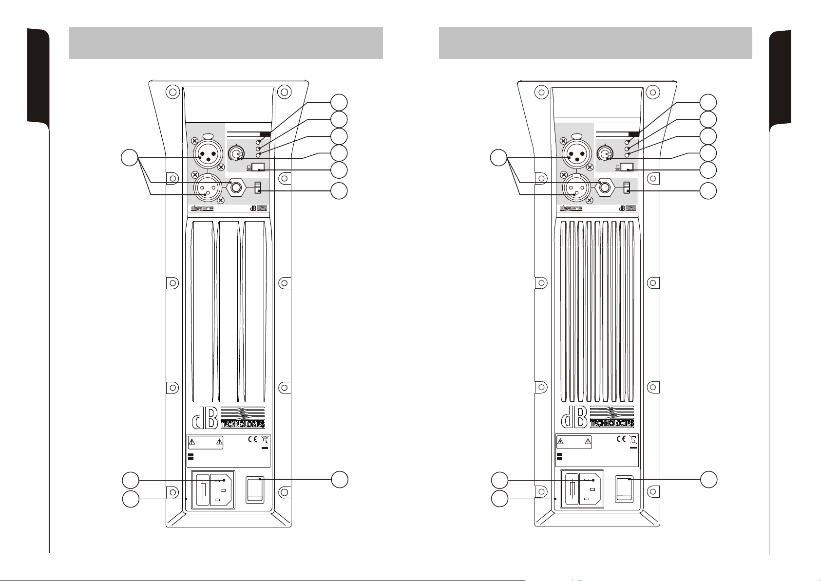
OPERA 208D
OPERA 208D
OPERA 210D
OPERA 210D
OPERA 410D - OPERA 402D - OPERA 405D
OPERA 410D - OPERA 402D - OPERA 405D
OPERA 602D - OPERA 605D
OPERA 602D - OPERA 605D
2
Balanced Input
1
Link
PUSHPUSH
digital power
OPERA
Sensitivity
+4dB
0dB
-3dB
88
Flat
Processed
DIGITAL ACTIVE SPEAKERDIGITAL ACTIVE SPEAKER
Input-Link
Input Sens
DD
Limiter
Signal
Ready
Line
Mic
3
4
5
1
6
7
Balanced Input
Link
PUSHPUSH
digital power
OPERA
Sensitivity
+4dB
0dB
-3dB
88
Flat
Processed
DIGITAL ACTIVE SPEAKERDIGITAL ACTIVE SPEAKER
Input-Link
Input Sens
DD
Limiter
Signal
Ready
Line
Mic
2
3
4
5
6
7
49
“CAUTION”
TO PREVENT ELECTRICAL SHOCK
DO NOT REMOVE COVER
“AVIS”
RISQUE DE CHOCH ELECTRIQUE
NE PAS OUVRIR
Internal voltage setup
220-240V~ 50-60Hz
110-120V~ 50-60Hz
FUSE MAINS
8
9
Made in Italy
MODULE POWER
CONSUMPTION
POWER
I
00
10
8
9
“CAUTION”
TO PREVENT ELECTRICAL SHOCK
DO NOT REMOVE COVER
“AVIS”
RISQUE DE CHOCH ELECTRIQUE
NE PAS OUVRIR
220-240V~ 50-60Hz
110-120V~ 50-60Hz
FUSE MAINS
Internal voltage setup
Made in Italy
MODULE POWER
CONSUMPTION
POWER
I
00
10
50
Page 27

DIMENSIONI / DIMENSIONS
ABMESSUNGEN / DIMENSIONS
DIMENSIONI / DIMENSIONS
ABMESSUNGEN / DIMENSIONS
OPERA 208DOPERA 208D
O
O
P
P
E
E
R
R
A
A
D
D
dd
d
d
dd
BB
B
B
BB
T
T
T
T
T
T
EH
EH
E
E
E
E
C
C
C
C
C
C
H
H
H
H
N
N
N
N
N
N
O
O
O
O
O
O
L
L
L
L
L
L
O
O
O
O
O
O
G
G
G
G
G
G
I
I
I
I
I
I
E
E
E
E
E
E
S
S
S
S
S
S
OPERA 210D
OPERA 210D
OPERA 410D
OPERA 410D
OP
ERAOPERA
DD
dd
dd
dd
BB
BB
BB
T
T
T
T
E
E
E
E
E
E
C
C
C
C
C
C
HN
HN
H
H
H
H
N
N
N
N
OL
OL
L
L
L
L
OG
OG
OGI
OGI
OGI
OGI
I
I
E
E
E
E
E
E
S
S
SO
SO
SOT
SOT
OPERA 402D
OPERA 402D
OPERA 405D
OPERA 405D
OPERA 602D
OPERA 602D
OPERA 605D
OPERA 605D
OPERAOPERA
DD
d
d
d
dd
d
B
B
B
BB
B
T
T
T
T
T
T
E
E
E
E
E
E
C
C
C
C
C
C
H
H
H
H
H
H
N
N
N
N
N
N
O
O
O
O
O
O
L
L
L
L
L
L
O
O
OG
OG
OG
OG
GIS
GIS
I
I
I
I
E
E
E
E
E
E
S
S
S
S
51
284284
43°43°
300300
655655
553553
484484
432432
43°43°
304304
353353
343343
43°43°
52
Page 28

ANGOLO DI COPERTURA TROMBA / HORN ANGLE COVERED
HOCHTONHORN ABSTRAHLWINKEL / ANGLE DE COUVERTURE COTE
65°
60°
SCHEMA A BLOCCHI - BLOCK DIAGRAM
BLOCKSCHALTBILD - SCHEMAS FONCTIONNELS
OPERA 208D
OPERA 210D
DIGIPRO
MAINS
L
N
FUSE
POWER
SWITCH
TRANSFORMER
®
INTERNAL
POWER
SUPPLY
200W
Long trough
80°
65°
80°
BALANCED
INPUTS
LINK
INPUT
SENS
SENSITIVITY
Digital Signal Processing
MODE
OPERA 410D OPERA 402D OPERA 405D
OPERA 602D OPERA 605D
MAINS
BALANCED
INPUTS
LINK
POWER
FUSE
L
SWITCH
N
INPUT
SENS
SENSITIVITY
DIGIPRO
Switching Mode
Power Supply
Digital Signal Processing
DSP
MICROPROCESSOR
SIGNAL
®
SMPS
DSP
DRIVER
Class D
WOOFER
Class D
READYLIMITER
400W
600W
DRIVER
Class D
53
Near field
MODE
MICROPROCESSOR
SIGNAL
WOOFER
Class D
66
READYLIMITER
54
Page 29

UTILIZZO IN APPOGGIO
SUPPORTED USE
ANWENDUNG
UTILISATION EN APPUI
O E
O E
P
P
R
R
A
A
D
D
dd
d
dd
d
BB
B
BB
B
T
T
T
T
T
T
E
E
E
E
E
E
C
C
C
C
C
C
H
H
H
H
H
H
N
N
N
N
N
N
O
O
O
O
O
O
L
L
L
L
L
L
O
O
O
O
O
O
G
G
G
G
G
G
I
I
I
I
I
I
E
E
E
E
E
E
S
S
S
S
S
S
UTILIZZO A PAVIMENTO (MONITOR)
FLOOR USES (MONITOR)
VERWENDUNG AUF DEM BODEN (MONITOR)
UTILISATION AU SOL (ÉCRAN)
d
d
d
d
d
d
B
B
B
B
B
B
D
SUPPORTO PIANTANA STANDARD (D36M)
STANDARD STAND (D36MM)
STANDARD-HOCHSTÄNDERFLANSCH (D36MM)
SUPPORT STANDARD (D36MM)
O
O
P
P
E
E
R
R
A
A
D
D
APPENDIBILE CON STAFFA (OPZIONALE)
APPENDIX BRACKET (OPTIONAL)
ANHANG BRACKET (OPTIONAL)
ANNEXE BRACKET (FACULTATIF)
Kit completo
OP
E
E
R
R
AOP
A
D
D
Complete kit
Opzione codice / Optional code
WB10 ---> OPERA 210D
OPERA 410D
WB12-15 ---> OPERA 402D
OPERA 405D
d
d
d
d
d
d
B
B
B
B
B
B
T
T
T
T
T
T
E
E
E
E
E
E
C O
C O
C
C
C
C
H
H
H
H
H
H
N
N
N
N
N
N
O
O
O
O
L
L
L
L
L
L
O
O
O
O
O
O
G
G
G
G
G
G
I
I
I
I
I
I
E
E
E
E
E
E
S
S
S
S
S
S
OPERA 602D
OPERA 605D
Fig. 1
OPE
OPER
R
A
A
DD
dd
dd
dd
BB
BB
BB
T
T
T
T
T
T
E
E
E
E
E
E
C
C
C
C
C
C
H
H
HNI
HNI
HNI
HNI
N
N
OS
OS
OS
OS
OS
OS
L
L
L
L
L
L
O
O
O
O
O
O
G
G
G
G
G
G
I
I
E
E
E
E
E
E
FIG. 4
COLLEGAMENTI
CONNECTIONS
Fig. 2
ANSCHL
ÜSSE
BRANCHEMENTS
Funzionamento sbilanciato con
connettore jack 1/4” (6,3mm)
Unbalanced use of stereo 1/4” jack plug
Punta = Segnale
Tip = Signal
PE
PE
R
R
AO
AO
D
D
Gambo=Schemo/Massa/Terra
Sleeve=Screen/Ground/Earth
Funzionamento bilanciato con
connettore jack 1/4” (6,3mm)
Balanced use of stereo 1/4” jack plug
Punta = Positivo/Caldo/Fase +VE
Tip = Positive/Hot/+VE Phase
Anello = Negativo/Freddo/Fase -VE
Ring=Negative/Cold/-VE Phase
Gambo=Schemo/Massa/Terra
Sleeve=Screen/Ground/Earth
55
d
d
d
d
d
d
B
B
B
B
B
B
T G
T G
T G
T G
T G
T G
E
E
E
E
E
E
C
C
CH
CH
CH
CH
H
H
N
N
N
N
N
N
O
O
O
O
O
O
L
L
L
L
L
L
O
O
O
O
O
O
I
I
I
I
I
I
E
E
E
E
E
E
S
S
S
S
S
dd
d
d
dd
BB
B
B
BB
T
T
T
T
T
T
E
E
E
E
E
E
C O
C O
C
C
C
C
H I
H I
H
H
H
H
N
N
N
N
N
N
O
O
O
O
L
L
L
L
L
L
O
O
O
O
O
O
G
G
G
G
G
G
I
I
I
I
E
E
E
E
E
E
S
S
S
S
S
S
S
FIG. 3
Punta
Tip
Funzionamento sbilanciato con
connettore XLR
Unbalanced use with XLR connectors
Ingresso
XLR - maschio
XLR - male
3
Input
Gambo
Sleeve
Pin 2 = Positivo/Caldo/Fase +VE
Pin 2 = Positive/Hot/+VE Phase
2
1
Pin 1 =Schermo/Terra/Massa
Pin 1 =Screen/Ground/Earth
Pin 3 = Connesso al Pin 1
Pin 3 = Link to Pin 1
Punta
Anello
Ring
Tip
Funzionamento bilanciato con
connettore XLR
Balanced use with XLR connectors
2
3
1
Ingresso
XLR - maschio
Input
XLR - male
Gambo
Sleeve
Pin 2 = Positivo/Caldo/Fase +VE
Pin 2 = Positive/Hot/+VE Phase
Pin 1 =Schermo/Terra/Massa
Pin 1 =Screen/Ground/Earth
Pin 3 =Negativo/Freddo/Fase -VE
Pin 3 =Negative/Cold/-VE Phase
56
 Loading...