

Page 1
MANUALE D’USO – Sezione 1
USER MANUAL - Section 1
BEDIENUNGSANLEITUNG - Abschnitt 1
CARACTERISTIQUES TECHNIQUES - Section 1
MANUAL DEL USUARIO - Sección 1
Le avvertenze nel presente manuale devono essere osservate congiuntamente al “MANUALE D’USO - Sezione2”.
The warnings in this manual must be observed together with the "USER MANNUAL- Section 2".
Die Warnungen in diesem Handbuch müssen in Verbindung mit der "BEDIENUNGSANLEITUNG - Abschnitt 2" beobachtet werden”.
Les avertissements speciés dans ce manuel doivent être respectés ainsi que les "CARACTERISTIQUES TECHNIQUES -Section 2".
Las advertencias del presente manual se deben tener en cuenta conjuntamente con las del “Manual del usuario” - Sección 2”.
Page 2

EMI CLASSIFICATION
According to the standards EN 55103 this equipment is designed and suitable to operate in E3 (or lower E2, E1)
Electromagnetic environments.
FCC CLASS B STATEMENT ACCORDING TO TITLE 47, CHAPTER I,
SUBCHAPTER A, PART 15, SUBPART B
This device complies with part 15 of the FCC Rules. Operation is subject to the following two conditions: (1) This
device may not cause harmful interference, and (2) this device must accept any interference received, including
interference that may cause undesired operation.
WARNING
Make sure that the loudspeaker is securely installed in a stable position to avoid any injuries or damages to
persons or properties. For safety reasons di not place one loudspeaker on top of another without proper fastening
systems. Before hanging the loudspeaker check all the components for damages, deformations, missing or
damaged parts that may compromise safety during installation. If you use the loudspeakers outdoor avoid spots
exposed to bad weather conditions.
Contact dBTechnologies for accessories to be used with the speakers. dBTechnologies will not accept any
responsibility for damages caused by inappropiate accessories or additional devices.
LVX XM15 Cod. 420120241 REV.1.0
2
Page 3

ITALIANO
ENGLISH
DEUTSCH
FRANÇAIS
ESPAÑOL
LVX XM15 Cod. 420120241 REV.1.0
3
Page 4

Italiano
INDICE
1. INFORMAZIONI GENERALI ................................................................................................... 5
BENVENUTI! ........................................................................................................................ 5
PANORAMICA INTRODUTTIVA .......................................................................................... 5
RIFERIMENTI PER L’UTENTE ................................................................................................ 5
CARATTERISTICHE MECCANICHE ED ACUSTICHE ............................................................. 6
DIMENSIONI ............................................................................................................................................... 6
COPERTURA ACUSTICA ............................................................................................................................. 6
CARATTERISTICHE DELLA SEZIONE DI AMPLIFICAZIONE E DI CONTROLLO ................... 7
SEZIONE DI INGRESSO, USCITA E CONTROLLO ........................................................................................ 8
SEZIONE DI ALIMENTAZIONE .................................................................................................................... 9
2. PRIMA ACCENSIONE ............................................................................................................ 10
CONTENUTO DELLA CONFEZIONE .................................................................................. 10
INSTALLAZIONE ................................................................................................................ 10
COLLEGAMENTO DEGLI INGRESSI .......................................................................................................... 10
COLLEGAMENTO DELL’ ALIMENTAZIONE ............................................................................................... 11
COLLEGAMENTO DELLE USCITE FRA PIÙ MODULI (rilancio dell’alimentazione) ................................ 12
COLLEGAMENTO DELLE USCITE FRA PIÙ MODULI (rilancio del segnale audio) ................................. 13
3. ESEMPI DI UTILIZZO ............................................................................................................. 14
UTILIZZO A TERRA COME MONITOR DA PALCO ............................................................ 14
UTILIZZO COME MONITOR PER DISTANZE MAGGIORI .................................................. 14
INSTALLAZIONE SU STAND TREPPIEDE ........................................................................... 14
4. AGGIORNAMENTO DEL FIRMWARE .................................................................................. 15
5. ACCESSORI ............................................................................................................................ 16
6. RISOLUZIONE DEI PROBLEMI ............................................................................................. 17
7. SPECIFICHE TECNICHE ......................................................................................................... 18
GENERALE ................................................................................................................................................ 18
DATI ACUSTICI .......................................................................................................................................... 18
AMPLIFICATORE ....................................................................................................................................... 18
PROCESSORE ............................................................................................................................................ 19
INTERFACCIA UTENTE .............................................................................................................................. 19
INGRESSI E USCITE ................................................................................................................................... 19
SPECIFICHE DI ALIMENTAZIONE (ASSORBIMENTO / INSTALLAZIONE) ................................................. 19
DIMENSIONI ............................................................................................................................................. 20
LVX XM15 Cod. 420120241 REV.1.0
4
Page 5

Italiano
1. INFORMAZIONI GENERALI
BENVENUTI!
Grazie per aver acquistato un prodotto progettato e sviluppato in Italia da dBTechnologies! Questo monitor attivo
coassiale professionale racchiude in sé anni di esperienza ed innovazione nel campo della diffusione sonora, con
l’impiego di soluzioni d’avanguardia in campo acustico, elettronico e di ricerca sui materiali.
PANORAMICA INTRODUTTIVA
LVX XM15 è un monitor attivo coassiale professionale, in congurazione bass-reex, equipaggiato con un woofer
da 15” (voice coil: 2.5”) e un driver a compressione con uscita da 1” (voice coil: 1.4”), pilotati da un amplicatore
DIGIPRO G3 da 600 W RMS di ultima generazione. Tra le caratteristiche principali ci sono:
• l’ottimizzazione acustica in congurazione reex e l’utilizzo del trasduttore coassiale, che garantisce
insieme compattezza meccanica, uniformità di copertura, estesa risposta in frequenza, una limitata
sensibilità al feedback e coerenza alla frequenza di cross-over;
• un’accentuata versatilità di utilizzo, con la scelta fra una doppia posizione come monitor da palco
oppure l’uso come sistema di amplicazione PA, montato su stand treppiede;
• la maneggevolezza e l’immediata congurabilità, grazie ai preset impostabili sul pannello
amplicatore in base all’utilizzo scelto;
• la qualità del cabinet in legno, rivestito con un robusto strato in PVC, che lo rende adatto ed afdabile
per tutti gli scenari di utilizzo, comprese lunghe turnée e congurazioni outdoor
RIFERIMENTI PER L’UTENTE
Per utilizzare al meglio il vostro LVX XM15 consigliamo di:
• leggere il manuale d’uso quick start presente nella confezione e questo manuale d’uso completo in
ogni sua parte e conservarlo per tutta la durata di vita del prodotto.
• registrare il prodotto sul sito http://www.dbtechnologies.com nella sezione “SUPPORTO”.
• scaricare ed installare il rmware più aggiornato dal sito http://www.dbtechnologies.com nella sezione
“DOWNLOADS” (vedi il capitolo AGGIORNAMENTO DEL FIRMWARE).
• conservare prova d’acquisto e GARANZIA (Manuale d’uso “sezione 2”).
LVX XM15 Cod. 420120241 REV.1.0
5
Page 6
CARATTERISTICHE MECCANICHE ED ACUSTICHE
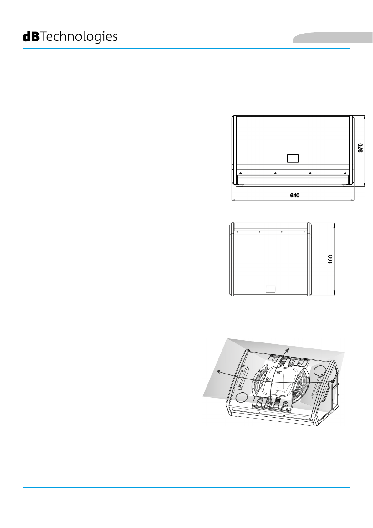
DIMENSIONI
LVX XM15 integra, in un cabinet di legno, protetto da un
rivestimento in PVC, del peso di 22,3 kg, un woofer da 15” (voice
coil:”2.5”) e un driver a compressione da 1” (voice coil:1.4”) in
congurazione coassiale. Gli ingombri di un singolo diffusore
sono: 640 x 460 x 370 mm. Le maniglie laterali consentono un
facile trasporto e lo spostamento del monitor anche da parte di
una sola persona. Il supporto per palo standard di diametro 35
mm consente inoltre un utilizzo in installazione come rinforzo
sonoro PA, oltre alla doppia congurazione monitor.
Italiano
COPERTURA ACUSTICA
La particolare apertura del monitor, schematizzata in gura,
garantisce una copertura di 90 x 70°. Questo permette in tutte
le congurazioni di utilizzo, di ottenere buone prestazioni di
dispersione, anche quando il monitor è utilizzato in posizione
verticale. La congurazione coassiale, inoltre, permette
un’ottima copertura anche fuori asse, oltre a garantire
eccellenti risultati all’ascolto a minima distanza.
LVX XM15 Cod. 420120241 REV.1.0
6
Page 7
Italiano
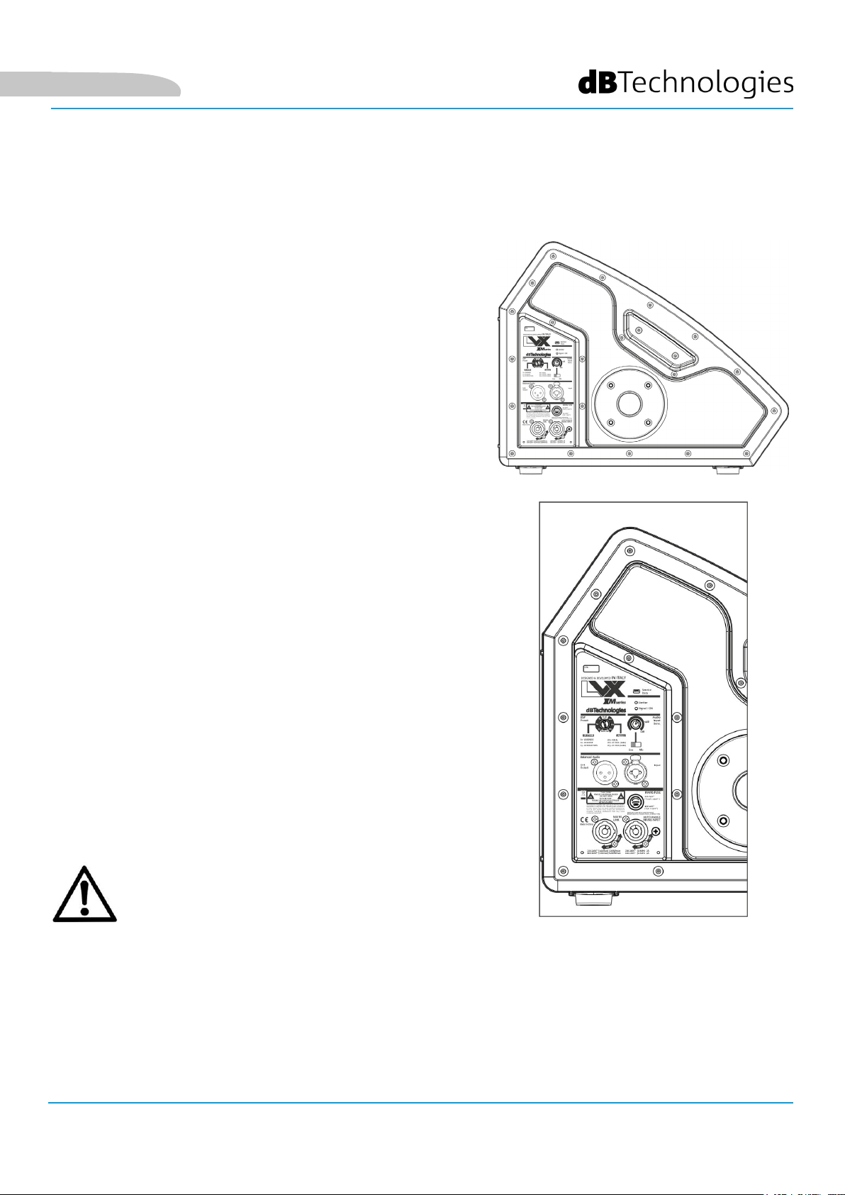
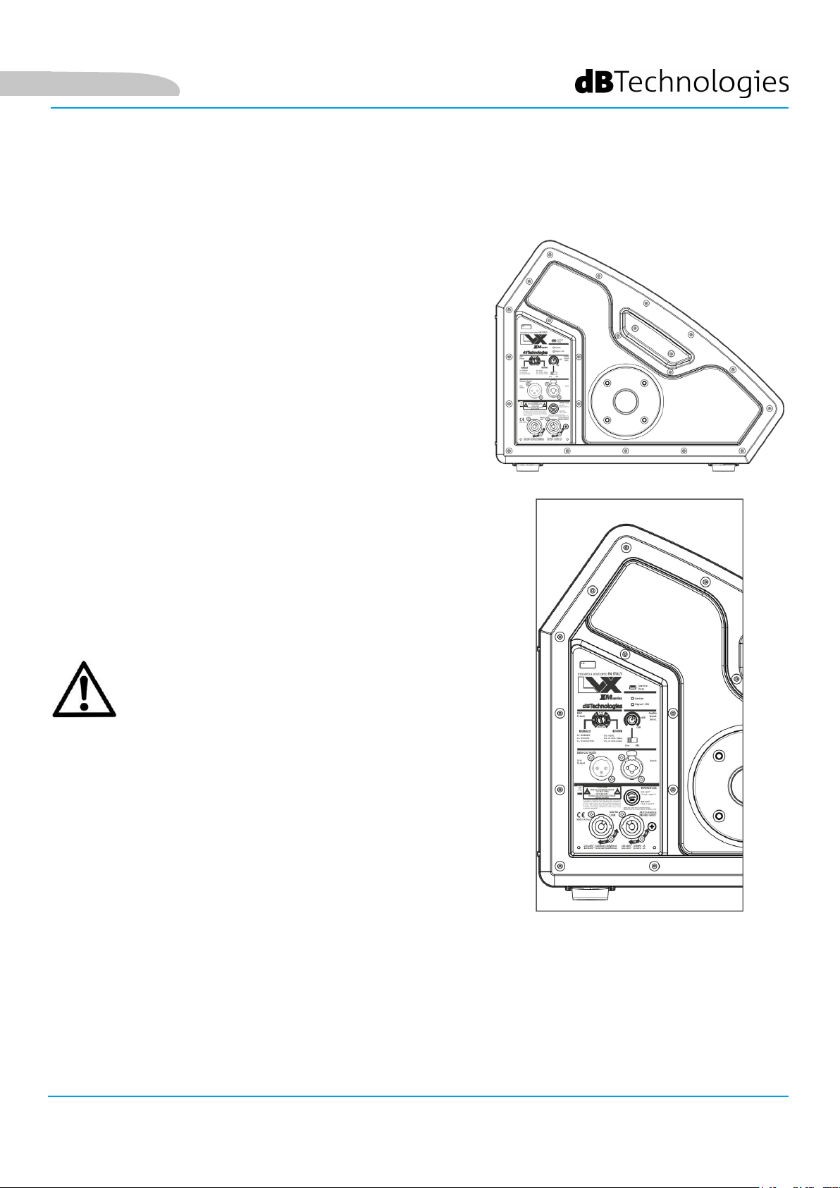
CARATTERISTICHE DELLA SEZIONE DI AMPLIFICAZIONE E DI CONTROLLO
L’amplicatore digitale di ultima generazione DIGIPRO G3,
in classe D, è il cuore di LVX XM15. Totalmente silenzioso, il
raffreddamento avviene senza l’ausilio di ventole, e assicura una
potenza di amplicazione di 600 W RMS. Tutti gli ingressi e i
controlli sono concentrati nel pannello amplicatore. Utilissimi
i preset preimpostabili tramite rotary che, grazie al DSP interno,
adattano il monitor alle varie esigenze di utilizzo.
Il pannello del DIGIPRO G3 è caratterizzato da:
• Sezione di Ingrresso, Uscita e Controllo
• Sezione di Alimentazione
ATTENZIONE!
• Proteggere il modulo dall’umidità.
• Non tentare in nessun modo di aprire
l’amplicatore.
• In caso di malfunzionamento, interrompere
immediatamente l’alimentazione, scollegando
il modulo dalla rete, e contattare un riparatore
autorizzato.
LVX XM15 Cod. 420120241 REV.1.0
7
Page 8
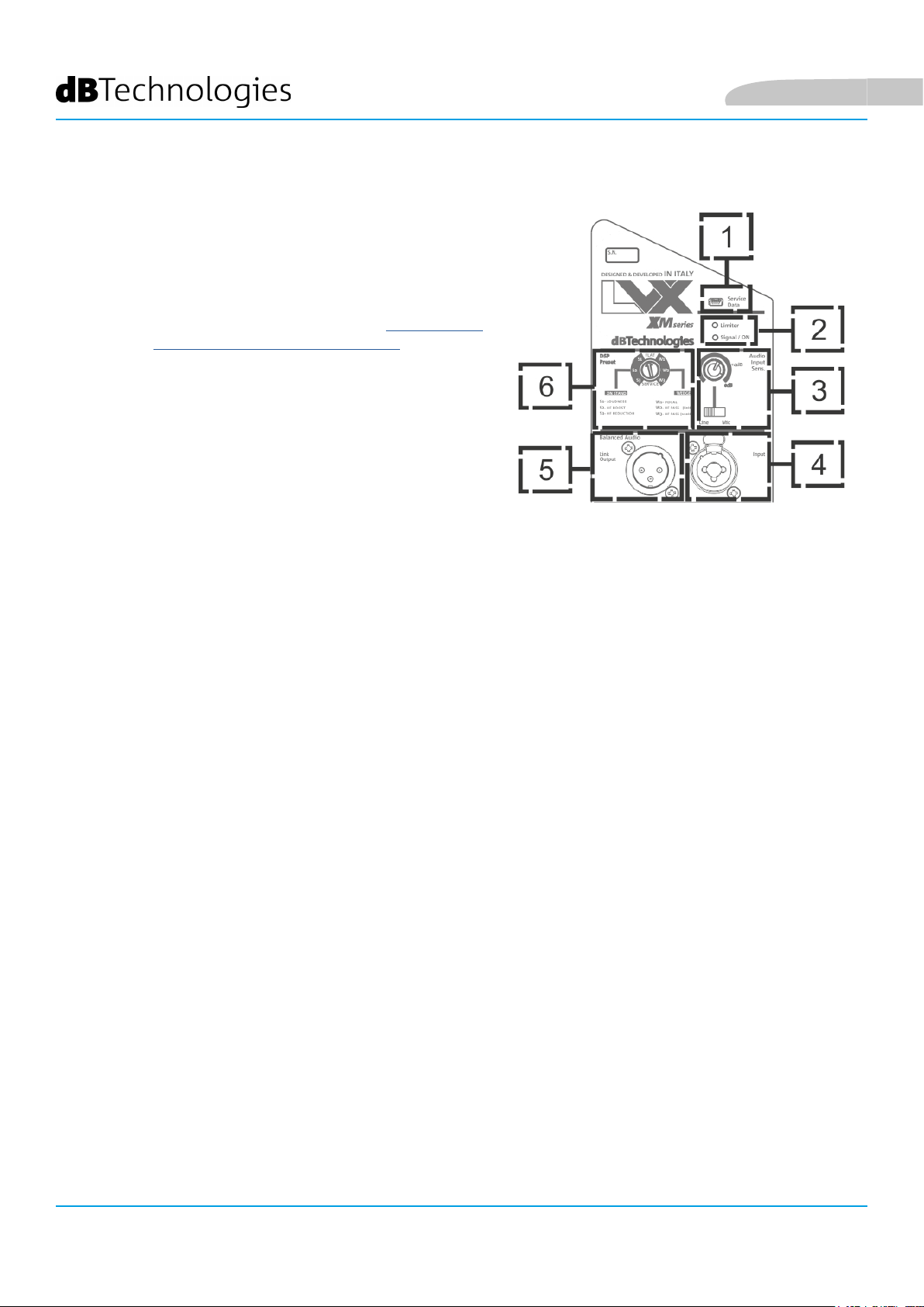
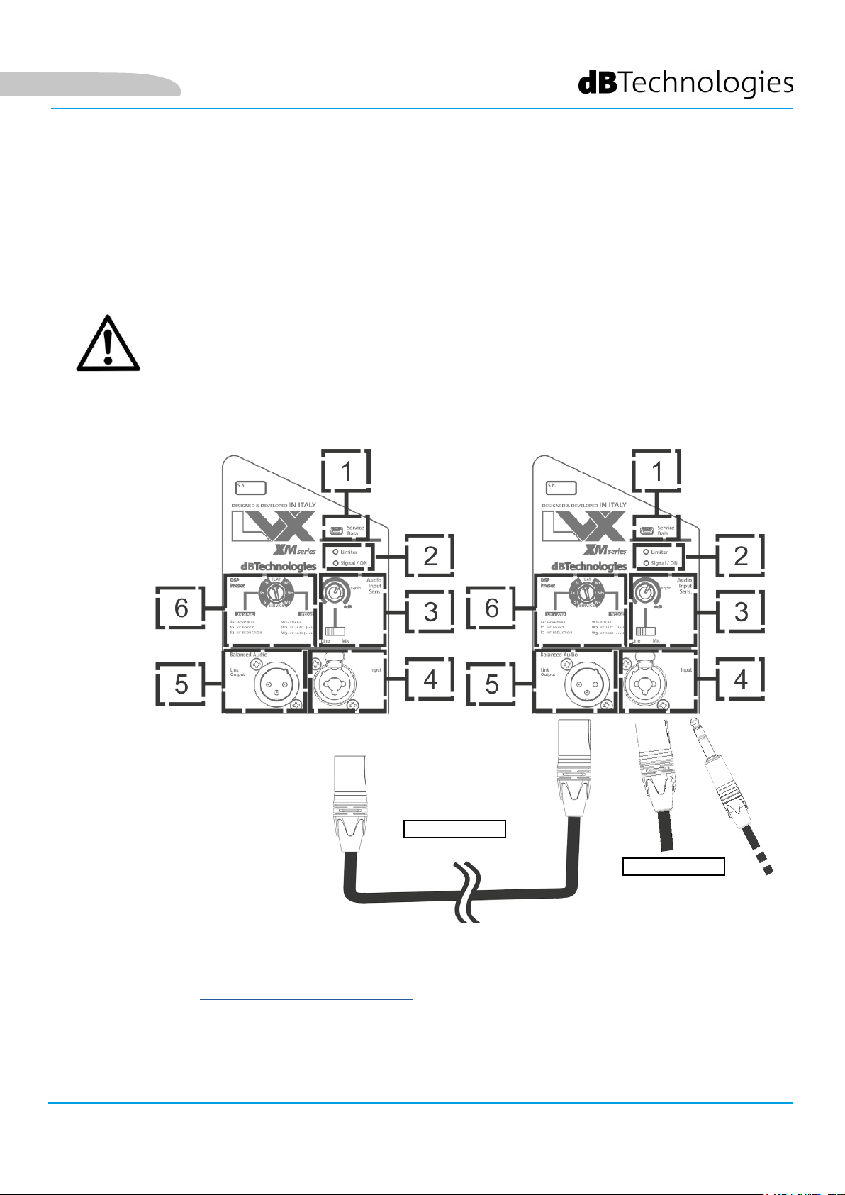
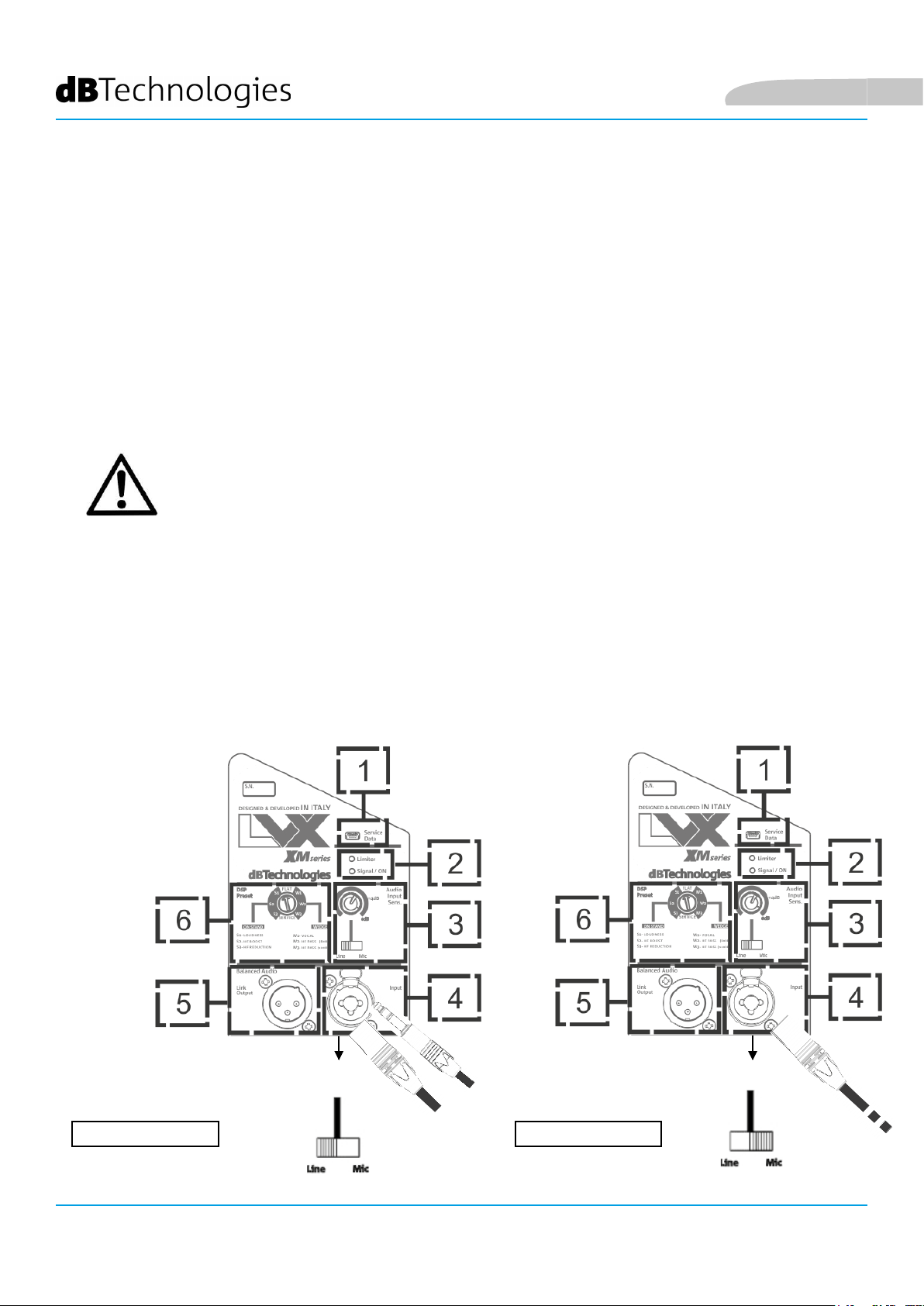
SEZIONE DI INGRESSO, USCITA E CONTROLLO
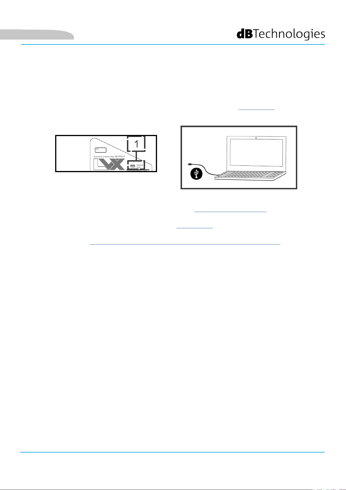
1. USB SERVICE DATA
Tramite questa porta standard mini-USB di tipo B è possibile,
tramite PC e USB BURNER MANAGER, aggiornare il rmware
del prodotto. Per ulteriori informazioni consultare il sito
http://www.dbtechnologies.com alla sezione “DOWNLOADS”
ed il capitolo AGGIORNAMENTO DEL FIRMWARE.
2. LED DI SEGNALAZIONE
I LED “Limiter” e “Signal / ON“ sono utili indicatori dello
stato del sistema. Il led “Limiter” segnala l’intervento
della protezione interna prima del raggiungimento di una
condizione di distorsione audio. Il led “Signal / ON” segnala
invece lo stato di accensione iniziale e lo stato di presenza di
segnale audio.
Italiano
3. AUDIO INPUT SENSITIVITY CON SELETTORE LINE/MIC
L’AUDIO INPUT SENSITIVITY permette di regolare il livello dell’ingresso. Tramite il selettore collegato è poi
possibile selezionarne la tipologia, scegliendo fra MIC (ingresso microfonico) e LINE (ingresso di linea/dal mixer).
4. INGRESSO - INPUT
Tramite il connettore Neutrik
bilanciato.
5. USCITA “LINK”
Uscita XLR bilanciata che permette di inviare il segnale audio ad un altro diffusore
amplicato.
6. DSP PRESET ROTARY
Controllo rotary a 8 posizioni , per la congurazione con preset preimpostati dell’equalizzazione del monitor
® combinato è possibile inserire sia un connettore jack TRS sbilanciato che un XLR
LVX XM15 Cod. 420120241 REV.1.0
8
Page 9

Italiano
SEZIONE DI ALIMENTAZIONE
7. FUSIBILE DI PROTEZIONE “MAINS FUSE”
Fusibile di rete.
8. INGRESSO DI ALIMENTAZIONE “AUTO-RANGE MAINS INPUT”
Ingresso per connettore POWERCON®.
9. USCITA DI RILANCIO DELL’ALIMENTAZIONE “MAINS LINK”
Grazie a questa connessione, è possibile rilanciare l’alimentazione a un secondo modulo.
ATTENZIONE!
• Il diffusore viene fornito con un fusibile già montato per operare nel
range 220-240 V. Se è necessario operare nel range di tensione 100-120 V:
1. Disconnettere ogni connessione, compresa l’alimentazione.
2. Attendere 5 minuti.
3. Sostituire il fusibile con quello fornito nella confezione per il range 100-120 V.
4. Utilizzare solo il cavo di alimentazione in dotazione.
• La connessione USB SERVICE DATA deve essere utilizzata esclusivamente per
aggiornamento rmware del prodotto, non connettere nessun dispositivo USB
all’apparecchio, per evitare danneggiamenti o malfunzionamenti.
• Non utilizzare il diffusore per un lungo periodo con il led limiter acceso o
lampeggiante, che indica un funzionamento di stress eccessivo in condizioni di
distorsione.
LVX XM15 Cod. 420120241 REV.1.0
9
Page 10

Italiano
2. PRIMA ACCENSIONE
CONTENUTO DELLA CONFEZIONE
Vericate, aprendo la confezione, che il contenuto dell’imballo del diffusore LVX XM15 sia completo. L’imballo
contiene:
• LVX XM15
• cavo di alimentazione con connettore POWERCON®
• quick start e documentazione relativa alla garanzia
• fusibile per il funzionamento nel range di tensione 100-120V
ATTENZIONE!
Il diffusore viene fornito con un fusibile già montato per operare nel range
220-240 V. Se è necessario operare nel range di tensione 100-120 V:
1. Disconnettere ogni connessione, compresa l’alimentazione.
2. Attendere 5 minuti.
3. Sostituire il fusibile con quello fornito nella confezione per il range 100-120 V.
4. Utilizzare solo il cavo di alimentazione in dotazione.
INSTALLAZIONE
COLLEGAMENTO DEGLI INGRESSI
MIXER / LINEA MICROFONO
LVX XM15 Cod. 420120241 REV.1.0
10
Page 11

Italiano
COLLEGAMENTO DELL’ ALIMENTAZIONE
• Collegare l’ingresso audio (4) correttamente, selezionando la sorgente attraverso il selettore “Input
sensitivity” (3). In caso di ingresso di segnale proveniente da ingresso di linea o da un’uscita mixer
impostare il selettore su “LINE”, in caso di ingresso microfonico (utilizzare un microfono dinamico),
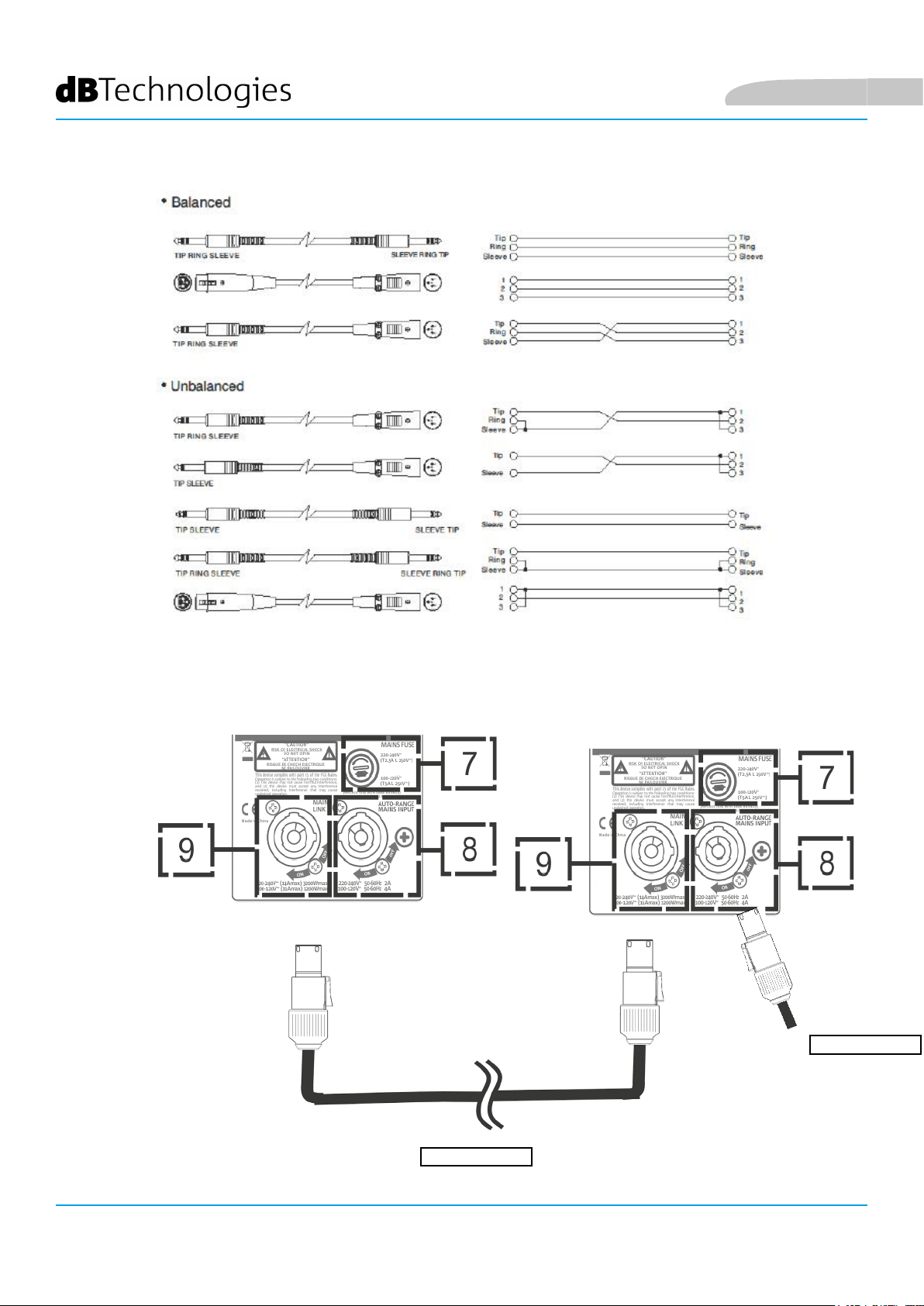
impostare il selettore su “MIC”. Per una veloce panoramica sui cavi audio confrontare la tabella
seguente.
• Collegare l’alimentazione connettendo il cavo con connettore POWERCON® a “MAINS INPUT” (8)
• All’accensione il led Signal/ON (2) lampeggia brevemente
• Ruotare l’encoder di Audio Input Sensitivity (3) per regolare il guadagno del sistema ad un livello
adeguato.
• Vericare che il diffusore, una volta connessa correttamente ed accesa la sorgente sonora, emetta il
suono, alzando il volume in maniera progressiva
• Impostare il DSP preset al valore desiderato:
1. FLAT - Imposta un’equalizzazione priva di enfasi sulla banda delle frequenze
2. WEDGE - Imposta un’equalizzazione enfatizzata per l’utilizzo di live monitoring
W1 - VOCAL, utile nell’utilizzo in particolare con cantato e parlato
W2 - HF PASS (80 Hz), per l’utilizzo con ltraggio della banda di frequenze da 80 Hz in su
W3 - HF PASS (120 Hz), per l’utilizzo con ltraggio della banda di frequenze da 120 Hz in su
3. SERVICE - Abilita l’aggiornamento del rmware (vedi la sezione relativa AGGIORNAMENTO DEL
FIRMWARE)
4. ON STAND - Imposta un’equalizzazione enfatizzata per l’utilizzo su palo (stand treppiede)
S1 - LOUDNESS ,che fornisce un aiuto in caso di rumore di fondo
S2 - HF BOOST, che esalta le basse frequenze
S3 - HF REDUCTION, che effettua una riduzione delle alte frequenze
ALIMENTAZIONE
LVX XM15 Cod. 420120241 REV.1.0
11
Page 12
Italiano
COLLEGAMENTO DELLE USCITE FRA PIÙ MODULI (rilancio dell’alimentazione)
ALIMENTAZIONE
RILANCIO
LVX XM15 Cod. 420120241 REV.1.0
12
Page 13
Italiano
Su LVX XM15, è possibile rilanciare l’alimentazione dal primo monitor ad uno successivo, no ad una corrente
massima di 14 A (3200 W) nei paesi con tensione di alimentazione 220-240Vac e di 11 A (1200 W) nei paesi con
tensione di alimentazione 100-120Vac. Per effettuare questo tipo di connessione è sufciente collegare il cavo di
alimentazione fornito a corredo sull’ingresso MAINS INPUT (8) del primo LVX XM15 e connettere un secondo cavo
con connettori adatti (opzionale) tra l’uscita MAINS LINK (9) e l’ingresso MAINS INPUT (8) di LVX XM15 successivo.
E’ possibile ripetere questo tipo di collegamento no al raggiungimento della massima corrente ammessa e
indicata dal connettore MAINS LINK (9) del primo monitor.
ATTENZIONE!
Il valore totale rilanciabile in potenza e corrente può essere differente a quello
nominale di targa. Questo dipende dal tipo di di cavo di alimentazione e di connettore
del primo modulo e dal collegamento successivo dei monitor in cascata. Tenerne conto
in fase di progettazione e installazione del sistema..
COLLEGAMENTO DELLE USCITE FRA PIÙ MODULI (rilancio del segnale audio)
RILANCIO
INGRESSO AUDIO
Per collegare 2 o più diffusori alla stessa sorgente audio, può essere utile, in diversi tipi di installazione,
rilanciarne il segnale da un primo a un secondo monitor e così via. Connettere innanzitutto una qualsiasi sorgente
sonora nell’ingresso “INPUT” (4) del primo diffusore (per il differente collegamento “LINE” o “MIC”
confrontare la sezione COLLEGAMENTO DEGLI INGRESSI). Collegare poi con un cavo
bilanciato XLR l’uscita “LINK” (5) del primo diffusore all’ingresso “INPUT” (4) del secondo. Questa seconda
operazione può essere poi ripetuta con più diffusori
LVX XM15 Cod. 420120241 REV.1.0
13
Page 14

3. ESEMPI DI UTILIZZO
• In congurazione monitor, pianicare l’installazione in modo da consentire
un’adeguata copertura acustica, il più possibile priva di ostacoli e tale da
scongiurare l’effetto Larsen (feedback).
UTILIZZO A TERRA COME MONITOR DA PALCO
L’utilizzo a terra come monitor da palco è facile e veloce. Vericare che l’eventuale
inclinazione del pavimento non sia tale da produrre uno scivolamento del
monitor. Porre particolare attenzione alla presenza di ostacoli davanti allo
speaker. Ricordare il pattern di dispersione presentato nella sezione COPERTURA
ACUSTICA.
Italiano
UTILIZZO COME MONITOR PER DISTANZE MAGGIORI
Tramite gli appositi piedini è possibile poggiare il monitor sul lato del dissipatore
dell’amplicatore come mostrato in gura. Questo permette di utilizzare lo
speaker come monitor con una copertura frontale per distanze maggiori sul palco.
In questo particolare tipo di utilizzo, il dissipatore può raggiungere temperature
elevate (supercie calda).
ATTENZIONE!
• il dissipatore del diffusore LVX XM può raggiungere alte temperature.
Prima di posizionare il diffusore in questa congurazione, vericare
che la supercie di appoggio sia realizzata in materiale resistente alle
alte temperature e comunque non propagante la amma.
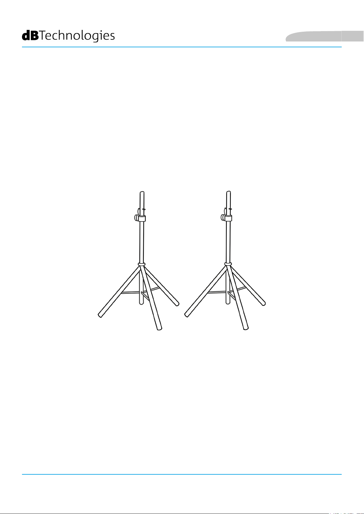
INSTALLAZIONE SU STAND TREPPIEDE
E’ possibile, grazie all’adattatore per palo diametro 35 mm, montare il monitor su
stand treppiede (SSB2). Vericare che lo stand abbia il piede centrale posizionato
in avanti per motivi di stabilità. La massima altezza consentita fra il pavimento e la
base del monitor è di 1,4 m.
ATTENZIONE!
• In contesti di utilizzo all’aperto, ancorare eventualmente il
diffusore per evitare oscillazioni dovute agli agenti atmosferici e
al vento.
• Utilizzare uno stand dimensionato opportunamente con il piede
centrale in avanti per assicurare una stabilità adeguata.
• Non utilizzare mai le maniglie per appendere il diffusore.
• Le uniche congurazioni ammesse sono quelle illustrate nel
presente manuale
LVX XM15 Cod. 420120241 REV.1.0
14
Page 15
Italiano
4. AGGIORNAMENTO DEL FIRMWARE
È molto importante mantenere aggiornato il rmware del prodotto, per garantirne una piena funzionalità.
Controllare periodicamente il sito http://www.dbtechnologies.com nella sezione “DOWNLOADS”.
1. Scaricare ed installare USB BURNER MANAGER nella sezione “SOFTWARE & CONTROLLER” sul proprio
computer.
2. Scaricare il le .zip dell’ultimo rmware nella sezione “DOWNLOADS” relativa al proprio prodotto.
3. Collegare il prodotto al PC tramite un cavo USB (non fornito) con il connettore del tipo corretto (vedere questo
dettaglio nel capitolo CARATTERISTICHE DELLA SEZIONE DI AMPLIFICAZIONE E DI CONTROLLO).
4. Nella schermata dell’USB BURNER MANAGER, in alto a destra, selezionare “Apertura File”.
5. Selezionare il le del rmware precedentemente scaricato.
6. Seguire le operazioni mostrate a video.
7. Cliccare “AGGIORNA”.
LVX XM15 Cod. 420120241 REV.1.0
15
Page 16
5. ACCESSORI
Per un rapido montaggio come sistema PA, è previsto come accessorio:
• SSB2, coppia di treppiedi diametro 35 mm, utile al montaggio di 2 LVX XM15 per l’utilizzo come
sistema di amplicazione PA. A lato del monitor, integrato nello chassis, si trova l’adattatore pole
mount adatto a questo scopo.
Italiano
Per ogni ulteriore informazione si prega di consultare il manuale relativo.
LVX XM15 Cod. 420120241 REV.1.0
16
Page 17

Italiano
6. RISOLUZIONE DEI PROBLEMI
Il diffusore non si accende:
1. Vericare la corretta presenza dell’alimentazione a monte dell’impianto.
2. Vericare che il cavo di alimentazione con connettore POWERCON® sia correttamente inserito.
3. In caso il problema persista, contattare l’assistenza.
Il diffusore si accende ma non emette nessun suono:
1. Vericare che i collegamenti in ingresso del segnale audio siano correttamente effettuati,
preferibilmente con cavi con con connettori Neutrik®.
2. Vericare che i cavi utilizzati non siano danneggiati.
3. Vericare che il mixer o la sorgente audio sia accesa e mostri chiaramente la presenza di segnale in
uscita.
4. Vericare che il livello di Audio Input Sensitivity (3) sul pannello di controllo dell’amplicatore sia
corretto.
Il diffusore emette un suono distorto:
1. A impianto acceso, regolare per primo il volume della sorgente, poi portare il rotary Audio Input
Sensitivity al valore più adeguato. Notare se il led di LIMITER è acceso, in questo caso indica un
funzionamento in condizioni di distorsione.
2. Vericare che i cavi utilizzati non siano danneggiati, nel qual caso sostituirli (un cavo danneggiato può
portare a perdita o alterazione del segnale).
3. Vericare che lo switch LINE-MIC rispecchi l’effettivo collegamento dell’ingresso.
4. Vericare le impostazioni del rotary DSP preset che inuiscono sulla risposta in frequenza in uscita. A tal
proposito consultare la sezione PRIMA ACCENSIONE.
Il monitoring sul palco non è sufciente
1. Vericare che il posizionamento sul palco sia corretto, in base al pattern di dispersione acustica indicato
e alle tipologie di posizioni illustrate nella sezione ESEMPI DI INSTALLAZIONE.
2. Vericare che non vi siano ostacoli diretti tra l’artista e il monitor a lui destinato.
3. Assicurarsi di aver impiegato il numero sufciente di LVX XM15.
LVX XM15 Cod. 420120241 REV.1.0
17
Page 18
7. SPECIFICHE TECNICHE
GENERALE
Italiano
Tipologia:
DATI ACUSTICI
Risposta in frequenza [-6dB]:
Max SPL (@ 1m):
HF compression diver (uscita):
HF Voice Coil:
Congurazione acustica:
Frequenza di crossover:
Copertura (HxV):
LF:
Monitor coassiale attivo a 2 vie per l’uso professionale
58 – 17800 Hz
128 dB
1”
1.4”
Reex
1700 Hz - 24 dB/oct
90° x 70°
15”
LF Voice coil:
2.5”
AMPLIFICATORE
Tipologia:
Classe di amplicazione:
Potenza di picco:
Potenza di amplicazione RMS:
LVX XM15 Cod. 420120241 REV.1.0
18
Digipro® G3
Classe D
1200 W
600 W
Page 19
Italiano
PROCESSORE
Controller interno:
Convertitore A/D D/A:
Limiter:
DSP 56 bit
28/56 bit/48 kHz
Peak, RMS, Termico
INTERFACCIA UTENTE
Wedge: [1] FLAT/ [2] VOCAL/ [3] HPF-80Hz/ [4] HPF-120Hz/
Presets:
Controlli:
Speaker: [6] HF reduction/ [7] HF boost/ [8] loudness
Rotary BCD 8 Pos, MIC LINE SWITCH
[5] Service
INGRESSI E USCITE
Ingressi audio: COMBO XLR, JACK 6,3 mm
Uscite audio:
1x XLR link OUT
USB (aggiornamento del rmware):
Mini USB di tipo B
SPECIFICHE DI ALIMENTAZIONE (ASSORBIMENTO / INSTALLAZIONE)
Assorbimento a 1/8 della potenza in
condizioni medie di utilizzo (*):
Assorbimento a 1/3 della potenza in
condizioni massime di utilizzo (**):
Assorbimento con speaker acceso in
assenza di segnale (idle):
Corrente di inrush: 0,72 A / 76 W
(230 V) - 1,22 A / 70 W (110 V)
Corrente e potenze totali ammesse in
un sistema rilanciato :
* NOTA PER L’INSTALLATORE: Valori riferiti a 1/8 della potenza, in condizioni medie di funzionamento (programma musicale con clipping raro
o assente). Si consiglia per qualsiasi tipo di congurazione di considerarli i valori minimi di dimensionamento.
** NOTA PER L’INSTALLATORE: Valori riferiti a 1/3 della potenza, in condizioni pesanti di funzionamento (programma musicale con frequente
clipping e intervento del limiter). E’ consigliabile il dimensionamento secondo questi valori in caso di installazioni e tour professionali.
1,01 A / 110 W (230 V) - 1,71 A / 113 W (115 V)
1,89 A / 230 W (230 V) - 3,2 A / 230 W (115 V)
19 W
27.3 A
14 A - 3200 W max (230 V) / 11 A - 1200 W max (115 V)
LVX XM15 Cod. 420120241 REV.1.0
19
Page 20
DIMENSIONI
Italiano
Materiale:
Griglia: Verniciata / lavorazione CNC
Predisposizione per y-bar:
Maniglie:
Montaggio su palo: Sì, 36 mm
Larghezza:
Altezza:
Profondità:
Peso:
Multistrato di legno con copertura di pvc
No
Integrate
640 mm
460 mm
370 mm
22,3 kg
LVX XM15 Cod. 420120241 REV.1.0
20
Page 21

Italiano
Caratteristiche, speciche e aspetto dei prodotti sono soggetti a possibili cambiamenti senza previa
comunicazione. dBTechnologies si riserva il diritto di apportare cambiamenti o miglioramenti nel design o nelle
lavorazioni senza assumersi l’obbligo di cambiare o migliorare anche i prodotti precedentemente realizzati.
A.E.B. Industriale Srl
Via Brodolini, 8
Località Crespellano
40053 VALSAMOGGIA
BOLOGNA (ITALIA)
Tel +39 051 969870
Fax +39 051 969725
www.dbtechnologies.com
info@dbtechnologies-aeb.com
LVX XM15 Cod. 420120241 REV.1.0
21
Page 22

English
TABLE OF CONTENTS
1. GENERAL INFORMATION .................................................................................................... 23
WELCOME! ....................................................................................................................... 23
PRODUCT OVERVIEW ....................................................................................................... 23
USER REFERENCE .............................................................................................................. 23
MECHANICAL AND ACOUSTICAL FEATURES ................................................................... 24
DIMENSIONS ............................................................................................................................................ 24
SOUND COVERAGE .................................................................................................................................. 24
FEATURES OF THE AMPLIFIER AND CONTROL SECTIONS .............................................. 25
INPUT, OUTPUT AND CONTROL SECTION .............................................................................................. 26
POWER SUPPLY UNIT SECTION ............................................................................................................... 27
2. FIRST POWER-UP .................................................................................................................. 28
PACKAGE CONTENTS ........................................................................................................ 28
INSTALLATION ................................................................................................................... 28
INPUT AND OUTPUT CONNECTIONS ...................................................................................................... 28
POWER SUPPLY CONNECTION ................................................................................................................ 29
CONNECTING THE OUTPUTS OF MULTIPLE MODULES (power daisy chain) ....................................... 30
CONNECTING THE OUTPUTS OF MULTIPLE MODULES (audio daisy chain) ........................................ 31
3. USAGE EXAMPLES ................................................................................................................ 32
FLOOR-STANDING STAGE MONITOR ............................................................................... 32
USAGE AS MONITOR FOR LONGER DISTANCES .............................................................. 32
USAGE ON TRIPOD STAND ............................................................................................... 32
4. FIRMWARE UPDATES ........................................................................................................... 33
5. ACCESSORIES ........................................................................................................................ 34
6. TROUBLESHOOTING ............................................................................................................ 35
6. SPECIFICATIONS ................................................................................................................... 36
GENERAL .................................................................................................................................................. 36
ACOUSTICAL SPECIFICATIONS ................................................................................................................. 36
AMPLIFIER ................................................................................................................................................ 36
PROCESSOR .............................................................................................................................................. 37
USER INTERFACE ...................................................................................................................................... 37
I/O ............................................................................................................................................................. 37
POWER SUPPLY SPECIFICATIONS ............................................................................................................ 37
DIMENSIONS ............................................................................................................................................ 38
LVX XM15 Cod. 420120241 REV.1.0
22
Page 23

English
1. GENERAL INFORMATION
WELCOME!
Thanks for purchasing a product designed and developed in Italy by dBTechnologies! This professional-grade
coaxial active monitor is the product of several years of experience and innovation in the sound reinforcement
industry, using cutting-edge sound, electronic and material research solutions.
PRODUCT OVERVIEW
LVX XM15 is a professional-grade coaxial active monitor in bass-reex conguration, equipped with a 15” woofer
(2.5” voice coil) and a compression driver with 1” output (1.4” voice coil), driven by a latest-generation 600 W RMS
DIGIPRO G3 amplier. Its main features include:
• sound optimization in reex conguration and a coaxial transducer that provides compact mechanical
layout, uniform coverage, broad frequency response range, low feedback sensitivity and coherence at
crossover frequency;
• enhanced versatility, offering two positions when used as a stage monitor or installation on a stand as
PA amplication system;
• ease of handling and quick conguration thanks to presets that can be set from the amplier panel to
suit specic application;
• high-quality wooden cabinet with rugged PVC coating make for reliable performance in all application
scenarios, including long tours and outdoor congurations
USER REFERENCE
To make the most of your LVX XM15, we recommend that you:
• Read the quick start user manual included in the package and this user manual thoroughly and keep
this manual during the whole life of the product.
• Register your product at http://www.dbtechnologies.com under “SUPPORT”.
• Download and install the latest rmware version at http://www.dbtechnologies.com under
“DOWNLOADS” (see section FIRMWARE UPDATES).
• Keep proof of purchase and WARRANTY (User manual “section 2”).
LVX XM15 Cod. 420120241 REV.1.0
23
Page 24

MECHANICAL AND ACOUSTICAL FEATURES
DIMENSIONS
LVX XM15 incorporates a 15” woofer (2.5” voice coil) and a 1”
compression driver (1.4” voice coil) in coaxial conguration
accommodated in a wooden cabinet protected by a PVC coating
and weighing 22,3 kg. The overall dimensions of a single
speaker are as follows: 640 x 460 x 370 mm. The monitor can be
easily carried and handled by a single person thanks to its side
handles. Standard 35-mm dia. pole mount allows for use in an
installation for PA sound reinforcement, as well as dual monitor
conguration.
English
SOUND COVERAGE
The monitor’s particular geometry shown in the diagram
ensures 90 x 70° coverage. This ensures good dispersion
performance in all use congurations, including vertical
arrangement. Coaxial conguration provides excellent off-
axis coverage and excellent sound results at close listening
distance.
LVX XM15 Cod. 420120241 REV.1.0
24
Page 25
English
FEATURES OF THE AMPLIFIER AND CONTROL SECTIONS
The latest-generation class-D digital amplier DIGIPRO G3 is at
core of LVX XM15. It features totally silent fanless cooling and
provides 600 W RMS amplication power. All inputs and controls
are gathered in the amplier panel. An internal DSP adapts the
monitor to different application requirements based on presets
that can be set using a rotary switch.
The DIGIPRO G3 panel is made up of:
• Input, Output and Control Section
• Power Supply Unit Section
WARNING!
• Protect the unit from moisture.
• Never attempt to disassemble the amplier in
any way.
• In the event of a malfunction, remove power
supply immediately by disconnecting the
unit from the power mains and contact an
authorised repair centre.
LVX XM15 Cod. 420120241 REV.1.0
25
Page 26

INPUT, OUTPUT AND CONTROL SECTION
1. SERVICE DATA USB PORT
This standard Mini-USB Type-B port enables user to update
product rmware using a PC and USB BURNER MANAGER.
More details are available at http://www.dbtechnologies.com
under “DOWNLOADS” and in section FIRMWARE UPDATES.
2. INDICATOR LEDs
The “Limiter” and “Signal / ON“ LEDs provide useful
indications about system status. The “Limiter” LED indicates
when the internal protection circuitry is active before a sound
distortion condition occurs. The “Signal / ON” LED turns on
when the module is powered on and indicates that an audio
signal is present.
3. AUDIO INPUT SENSITIVITY WITH LINE/MIC SELECTOR
AUDIO INPUT SENSITIVITY controls input level. The connected selector toggles input type between MIC
(microphone input) and LINE (line/mixer input).
English
4. INPUT
The hybrid Neutrik
5. “LINK” OUTPUT
Balanced XLR output intended to send the audio signal to another amplied speaker.
6. DSP PRESET ROTARY SWITCH
8-position rotary switch to set monitor equalisation using presets
® connector accepts both an unbalanced TRS jack and a balanced XLR connector.
LVX XM15 Cod. 420120241 REV.1.0
26
Page 27

English
POWER SUPPLY UNIT SECTION
7. MAINS FUSE
Mains protection fuse.
8. AUTO-RANGE MAINS INPUT
POWERCON connector input.
9. “MAINS LINK” POWER OUTPUT
This connector is intended to supply power to a second module.
WARNING!
• The fuse installed at the factory is rated for operation in the 220-240 V
voltage range. If you need to operate the speaker in the 100-120 V range:
1. Disconnect all connections, including the power supply connection.
2. Wait 5 minutes.
3. Replace the fuse with the fuse rated for the 100-120 V range, which is included in the
package.
• Use the SERVICE DATA USB port to update product rmware only. Do not connect
any USB devices to the unit to avoid damage or malfunctioning.
• Do not use the speaker for long periods of time when the Limiter LED is on or
blinking, as this indicates that the module is operating under exceeding stress
under distortion conditions.
LVX XM15 Cod. 420120241 REV.1.0
27
Page 28
English
2. FIRST POWER-UP
PACKAGE CONTENTS
When you open the LVX XM15 speaker package, ensure that all contents are present. The package contains:
• LVX XM15
• power supply cable with POWERCON® connector
• quick start user manual and warranty documents
• fuse rated for operation in the 100-120V voltage range
WARNING!
The fuse installed at the factory is rated for operation in the 220-240 V
voltage range. If you need to operate the speaker in the 100-120 V range:
1. Disconnect all connections, including the power supply connection.
2. Wait 5 minutes.
3. Replace the fuse with the fuse rated for the 100-120 V range, which is included in the package.
4. Use only the supplied power supply cable.
INSTALLATION
INPUT AND OUTPUT CONNECTIONS
MIXER / LINE MICROPHONE
LVX XM15 Cod. 420120241 REV.1.0
28
Page 29

English
POWER SUPPLY CONNECTION
• Connect the audio input (4) properly, selecting the source with the “Input sensitivity” selector (3). Set
selector to “LINE” if the input signal is coming from a line input or a mixer output, or to “MIC” for a
microphone input (use a dynamic microphone). Please see the table below for a quick overview of
audio cables.
• To connect the power supply, connect the cable with the POWERCON connector to “MAINS INPUT” (8)
• The Signal/ON LED (2) will blink briey at power-up
POWER SUPPLY
• Turn the Audio Input Sensitivity encoder (3) to adjust system gain to the appropriate level.
• When you have connected the audio source properly and switched it on, raise the volume gradually to
ensure that the speaker is producing sound
• Set the DSP preset to the desired value:
1. FLAT - Equalisation without emphasis in a particular frequency range
2. WEDGE - Equalisation with emphasis for live monitoring purposes
W1 - VOCAL, convenient for voice (speech and vocals)
W2 - HF PASS (80 Hz), for use with ltering of the frequency band from 80 Hz and higher
W3 - HF PASS (120 Hz), for use with ltering of the frequency band from 120 Hz and higher
3. SERVICE - Enables rmware update (see section FIRMWARE UPDATES)
4. ON STAND - Equalisation with emphasis for pole mount application (tripod stand)
S1 - LOUDNESS, helps with background noise
S2 - HF BOOST, boosts low frequencies
S3 - HF REDUCTION, reduces high frequencies
LVX XM15 Cod. 420120241 REV.1.0
29
Page 30

English
CONNECTING THE OUTPUTS OF MULTIPLE MODULES (power daisy chain)
POWER SUPPLY
DAISY CHAIN
LVX XM15 Cod. 420120241 REV.1.0
30
Page 31

English
LVX XM15 can supply mains power to another monitor up to a maximum current draw of 14 A (3200 W)
when operating at 220-240Vac or up to 11 A (1200 W) when operating at 100-120Vac. To perform this type of
connection, simply connect the supplied power supply cable to the MAINS INPUT (8) of the rst LVX XM15 module
and connect a second (optional) cable with suitable connectors across the MAINS LINK output (9) and the MAINS
INPUT (8) of the next LVX XM15 module in the chain. Several modules can be connected in this manner up to the
maximum current draw allowed that is indicated on the MAINS LINK connector (9) of the rst monitor.
WARNING!
The maximum current draw allowed indicated in the rating data of LVX XM15 (MAINS LINK) is calculated
based on the maximum current specication of the PowerCON connector. However, this is not a xed
value as it depends on the type of cable (cross-section area and type of plug) used to connect the rst
LVX XM15 module and on the next LINK cables (cross-section area and type of cable) in the chain. Always
check the maximum current (and power) specications and the cross-section areas of the cable leads used
when designing and sizing the sound system, and anyway before connecting several modules in a daisychain connection.
CONNECTING THE OUTPUTS OF MULTIPLE MODULES (audio daisy chain)
DAISY CHAIN
AUDIO INPUT
To connect 2 or more speakers to the same audio source in certain installations, you may nd it convenient
to daisy chain the signal from a rst module to the next and so on. First, connect an audio source
to “INPUT” (4) of the rst speaker (for the different “LINE” or “MIC” connection,
please read section INPUT CONNECTIONS). Next, connect a
balanced XLR cable across the “LINK” output (5) of the rst speaker and the “INPUT” (4) of the next speaker.
Repeat this second step to connect additional speakers until achieving the installation that best suits the
specic application.
LVX XM15 Cod. 420120241 REV.1.0
31
Page 32

3. USAGE EXAMPLES
• In the monitor conguration, plan installation so as to ensure appropriate
sound coverage, with as few obstacles as possible, and such to avoid the
Larsen effect (audio feedback).
FLOOR-STANDING STAGE MONITOR
Usage as stage audio monitor is quick and easy. Determine oor slope (if any) to
ensure that the monitor will not slide. Check for obstacles in front of the speaker.
Consider the dispersion pattern shown in section SOUND COVERAGE.
English
USAGE AS MONITOR FOR LONGER DISTANCES
The monitor has suitable feet that allow it to be placed with the amplier heatsink side facing down as shown in the gure. This way, the speaker can be used as
a monitor with greater front coverage on the stage. This particular arrangement
can cause the heat sink to become very hot (hot surface).
WARNING!
• The heat sink of the LVX XM speaker can become very hot. Before
placing the speaker in this mounting conguration, ensure that the
surface it is to be placed on is made from material resistant to high
temperatures and not propagating ame.
USAGE ON TRIPOD STAND
A pole mount socket with 35-mm diameter is provided to mount the monitor on
a tripod stand. Ensure that the tripod centre leg is pointing forward to improve
stability. Maximum mounting height (height of monitor’s bottom side above oor)
is 1.4 m.
WARNING!
• In outdoor applications, consider anchoring the speaker to
prevent swinging due to weather or wind.
• Use a suitably sized stand with the central leg pointing forward
to provide appropriate stability.
• Never hand the speaker from the handles.
• The only congurations allowed are those shown in this manual
LVX XM15 Cod. 420120241 REV.1.0
32
Page 33

English
4. FIRMWARE UPDATES
It is very important to keep product rmware updated to the latest version to ensure full performance. Please
check site http://www.dbtechnologies.com for updates under section “DOWNLOADS” periodically.
1. Download USB BURNER MANAGER from section “SOFTWARE & CONTROLLER” of the dBTechnologies site.
2. Download the .zip le with the last rmware from section “DOWNLOADS” for your product
3. Connect the product to the PC by means of a USB cable (not supplied) featuring the right connector detail is
contained in section FEATURES OF THE AMPLIFIER AND CONTROL SECTIONS
4. In the top right corner of the USB BURNER MANAGER screen, select “File Opening”.
5. Select the rmware le you have downloaded previously (ensure that it is suitable for your operating system).
6. Follow the on-screen instructions.
7. Click UPDATE.
LVX XM15 Cod. 420120241 REV.1.0
33
Page 34

5. ACCESSORIES
This option is available for quick mounting and use as PA system:
• SSB2, pair of tripods with 35-mm diameter to mount 2 LVX XM15 monitors for use as PA amplication
system. A pole mount socket suitable for the purpose is integrated in the chassis on monitor side.
English
Please read the corresponding manual for more details.
LVX XM15 Cod. 420120241 REV.1.0
34
Page 35

English
6. TROUBLESHOOTING
The speaker will not turn on:
1. Check that power supply is present upstream of the installation.
2. Ensure that the power supply cable with POWERCON connector is properly plugged in.
3. If the problem persists, contact service.
The speaker turns on but produces no sound:
1. Ensure that audio signal input connections have been performed properly, preferably using cables with
Neutrik® connectors.
2. Check the cables for damage.
3. Ensure that the mixer or audio source is on and an output signal is present.
4. Check for the proper Audio Input Sensitivity level (3) at the amplier control panel.
Speaker sound is distorted:
1. With the system on, rst adjust source volume, and then set the Audio Input Sensitivity rotary switch
to the appropriate value. Look at the LIMITER LED; if on, it means that the speaker is operating under
distortion conditions.
2. Check the cables for damage and replace them as required (a damaged cable may lead to signal loss or
alteration).
3. Ensure that the LINE-MIC switch is set to match actual input connection.
4. Check the settings of the DSP preset rotary switch that affect output frequency response. To this end,
please read section FIRST POWER-UP.
Stage monitoring is insufcient
1. Ensure that the speaker is properly positioned on the stage according to the indicated sound dispersion
pattern and the positions shown in section INSTALLATION EXAMPLES.
2. Check for any obstacles directly between performer and monitor.
3. Consider adding more LVX XM15 modules.
LVX XM15 Cod. 420120241 REV.1.0
35
Page 36

6. SPECIFICATIONS
GENERAL
English
Type:
ACOUSTICAL SPECIFICATIONS
Frequency response [-6dB]:
Max SPL (@ 1m):
HF compression driver (output):
HF Voice Coil:
Acoustic conguration:
Crossover frequency:
Coverage (HxV):
LF:
Professional-grade 2-way coaxial active monitor
57 – 17800 Hz
128 dB
1”
1.4”
Reex
1700 Hz - 24 dB/oct
90° x 70°
15”
LF Voice coil:
2.5”
AMPLIFIER
Type:
Amplication class:
Peak power:
RMS amplier power:
LVX XM15 Cod. 420120241 REV.1.0
36
Digipro® G3
Class D
1200 W
600 W
Page 37

English
PROCESSOR
Internal controller:
A/D D/A converter:
Limiter:
DSP 56 bit
28/56 bit/48 kHz
Peak, RMS, Termico
USER INTERFACE
Wedge: [1] FLAT/ [2] VOCAL/ [3] HPF-80Hz/ [4] HPF-120Hz/
Presets ():
Speaker: [6] HF reduction/ [7] HF boost/ [8] loudness
Controls: Rotary BCD 8 Pos, MIC LINE SWITCH
[5] Service
I/O
Inputs: COMBO XLR, 6.3 mm JACK
Outputs:
USB:
1x XLR link OUT
Type-B Mini-USB port
POWER SUPPLY SPECIFICATIONS
Draw at 1/8 of full power in average
use conditions (*):
Draw at 1/3 of full power in
maximum use conditions (**):
Draw with speaker turned on without
signal (idle): :
Inrush current:
Total current and power allowed in
daisy-chain conguration:
* INSTALLER NOTES: The values refer to 1/8 of full power, in average operating conditions (music program with infrequent or no clipping). It
is recommended to consider them the minimum sizing values for any type of conguration.
** INSTALLER NOTES: The values refer to 1/3 of full power, in heavy operating conditions (music program with frequent clipping or activation
of the limiter). We recommend sizing according to these values in case of professional installations and tours.
1,01 A / 110 W (230 V) - 1,71 A / 113 W (115 V)
1,89 A / 230 W (230 V) - 3,2 A / 230 W (115 V)
19 W
27.3 A
14 A - 3200 W max / 11 A - 1200 W max
LVX XM15 Cod. 420120241 REV.1.0
37
Page 38

DIMENSIONS
English
Material:
Grille:
Provisions for y bar:
Handles:
Pole mount: Yes, 36 mm
Width:
Height:
Depth:
Weight:
Plywood with PVC coating
Paint-nished / NC-machined
No
Integrated
640 mm
460 mm
370 mm
22,3 kg
LVX XM15 Cod. 420120241 REV.1.0
38
Page 39

English
Product features, specications and appearance are subject to changes without prior notice. dBTechnologies
reserves the right to make changes or improvements in design or manufacture without any obligation to
incorporate such changes or improvements in products manufactured before their introduction.
A.E.B. Industriale Srl
Via Brodolini, 8
Località Crespellano
40053 VALSAMOGGIA
BOLOGNA (ITALIA)
Tel +39 051 969870
Fax +39 051 969725
www.dbtechnologies.com
info@dbtechnologies-aeb.com
LVX XM15 Cod. 420120241 REV.1.0
39
Page 40

INHALT
1. ALLGEMEINE INFORMATIONEN ......................................................................................... 43
WILLKOMMEN! ................................................................................................................ 43
ÜBERSICHT ........................................................................................................................ 43
HINWEISE FÜR DEN BENUTZER ....................................................................................... 43
MECHANISCHE UND AKUSTISCHE EIGENSCHAFTEN ...................................................... 44
ABMESSUNGEN ........................................................................................................................................ 44
ABSTRAHLVERHALTEN ............................................................................................................................. 44
EIGENSCHAFTEN DES VERSTÄRKER- UND STEUERTEILS ................................................ 45
EINGANGS- UND STEUERTEIL ................................................................................................................. 46
NETZTEIL .................................................................................................................................................. 47
2. ERSTMALIGES EINSCHALTEN .............................................................................................. 48
VERPACKUNGSINHALT ..................................................................................................... 48
INSTALLATION ................................................................................................................... 48
ANSCHLUSS DER EINGÄNGE ................................................................................................................... 48
ANSCHLUSS DER STROMVERSORGUNG ................................................................................................. 49
VERLINKUNG DER AUSGÄNGE MEHRERER LAUTSPRECHER (Mains Link) ............................................ 50
VERLINKUNG DER AUSGÄNGE MEHRERER LAUTSPRECHER (Tonsignal-Link) ...................................... 51
3. INSTALLATIONSBEISPIELE ................................................................................................... 52
BODENAUFSTELLUNG ALS STAGE-MONITOR ................................................................. 52
INSTALLATION ALS MONITOR FÜR GRÖSSERE ENTFERNUNGEN .................................. 52
INSTALLATION AUF HOCHSTÄNDER ................................................................................ 52
4. AKTUALISIERUNG DER FIRMWARE ................................................................................... 53
5. ZUBEHÖR .............................................................................................................................. 54
6. PROBLEMLÖSUNG ............................................................................................................... 55
7. TECHNISCHE ANGABEN ...................................................................................................... 56
ALLGEMEINES .......................................................................................................................................... 56
AKUSTIKDATEN ........................................................................................................................................ 56
VERSTÄRKER ............................................................................................................................................ 56
PROZESSOR .............................................................................................................................................. 57
BENUTZEROBERFLÄCHE .......................................................................................................................... 57
I/O ............................................................................................................................................................. 57
ANGABEN ZUR STROMVERSORGUNG .................................................................................................... 57
ABMESSUNGEN ........................................................................................................................................ 58
Deutsch
LVX XM15 Cod. 420120241 REV. 1.0
40
Page 41

Deutsch
1. ALLGEMEINE INFORMATIONEN
WILLKOMMEN!
Wir bedanken uns für den Kauf dieses in Italien von dBTechnologies konstruierten und entwickelten Produkts!
Dieser professionelle, koaxiale Aktivlautsprecher basiert auf einer jahrelangen Erfahrung und Innovation im
Bereich der Beschallungstechnik, mit dem Einsatz hochmoderner technologischer Lösungen in der Akustik,
Elektronik und Materialforschung.
ÜBERSICHT
Der LVX XM15 ist ein professioneller, koaxialer Aktivmonitor in Bassreex-Bauweise mit einem 15"-Tieftöner
(Schwingspule: 2,5") und einem 1"-Kompressionstreiber (Schwingspule: 1,4"), die von einer DIGIPRO-G3-
Endstufe der letzten Generation mit einer Leistung von 600 W RMS angesteuert werden. Unter den wichtigsten
Eigenschaften ndet man:
• die akustische Optimierung durch die Reex-Konguration und Einsatz eines Koax-Transducers,
der mechanische Kompaktheit, homogene Abstrahlung, breiten Frequenzgang, geringste
Rückkopplungsneigung und Konstanz der Übergangsfrequenz gewährleistet;
• große Einsatzvielseitigkeit, Auswahl zwischen doppelter Aufstellmöglichkeit als Stage-Monitor
oder dem Einsatz als PA-Verstärkeranlage auf Hochständer;
• die Handlichkeit und unmittelbare Kongurierbarkeit dank den über das Verstärker-Steuerfeld
je nach gewählter Verwendung einstellbaren Presets;
• die Qualität des Holzgehäuses mit widerstandsfähiger PVC-Beschichtung für verschiedenartigste
Einsatz-Szenarien, inklusive lange Tourneen und in Außenbereichen.
HINWEISE FÜR DEN BENUTZER
Für die optimale Verwendung Ihres LVX XM15 wird empfohlen:
• die Quick-Start-Anleitung in der Verpackung und dieses Handbuch in allen seinen Teilen aufmerksam
durchzulesen; es muss während der gesamten Lebensdauer des Produkts aufbewahrt werden;
• das Produkt auf der Website http://www.dbtechnologies.com, Sektion „SUPPORTO“, zu registrieren;
• die aktuellste Firmware auf der Website http://www.dbtechnologies.com, Sektion „DOWNLOADS“
(siehe Kapitel AKTUALISIERUNG DER FIRMWARE), herunterzuladen und zu installieren;
• den Kaufbeleg und die GARANTIE (Bedienungsanleitung „Sektion 2“) aufzubewahren.
LVX XM15 Cod. 420120241 REV.1.0
41
Page 42

MECHANISCHE UND AKUSTISCHE EIGENSCHAFTEN
ABMESSUNGEN
Der LVX XM15 nimmt in seinem mit robustem PVCbeschichteten Holzgehäuse und mit einem Gewicht von
22,3 kg einen 15"-Tieftöner (Schwingspule: 2,5") und einen
1"-Kompressionstreiber (Schwingspule: 1,4") in koaxialer
Bauweise auf. Die Maße des einzelnen Lautsprechers sind:
640 x 460 x 370 mm. Dank den seitlichen Griffen ist dieser
Lautsprecher auch von einer Person leicht transportierbar.
Der Hochständeransch mit dem Standarddurchmesser von
35 mm ermöglicht außer der Doppelmonitor-Konguration
die Integration hoher Leistung in PA-Systeme.
Deutsch
ABSTRAHLVERHALTEN
Der besondere Abstrahlwinkel des Monitors, der auf der
Abbildung dargestellt ist, ermöglicht eine Abstrahlung von
90° x 70°. Dadurch wird bei allen Einsatzkongurationen
eine gute Schallverteilung auch bei vertikaler Position des
Monitors erzielt. Die koaxiale Bauweise ermöglicht eine gute
akustische Schallverteilung auch außerhalb der Achse sowie
ausgezeichnete Resultate bei geringstem Hörabstand.
LVX XM15 Cod. 420120241 REV. 1.0
42
Page 43

Deutsch
EIGENSCHAFTEN DES VERSTÄRKER- UND STEUERTEILS
Der digitale Hochleistungsverstärker mit der DIGIPRO-G3Technologie der letzten Generation ist das Herz des LVX
XM15. Für die Kühlung dieser völlig geräuschlos arbeitenden
Endstufe wird auf Lüfter verzichtet und ihre Leistung beträgt
600 W RMS. Alle Eingänge und Steuerelemente sind auf dem
Verstärker-Steuerfeld zusammengefasst. Sehr nützlich sind
die über Drehknöpfe einstellbaren, vordenierten Presets,
die den Monitor dank dem internen DSP an die wechselnden
Einsatzanforderungen anpassen.
ACHTUNG!
• Den Lautsprecher vor Feuchtigkeit schützen.
• Auf keinen Fall versuchen, den Verstärker zu
öffnen.
• Im Fall einer Funktionsstörung sofort die
Netzspannungsversorgung unterbrechen und
sich an einen autorisierten Reparaturdienst
wenden.
Die Steuertafel des DIGIPRO-G3 umfasst:
• Eingangs- und Steuerteil
• Netzteil
LVX XM15 Cod. 420120241 REV.1.0
43
Page 44

Deutsch
EINGANGS- UND STEUERTEIL
1. USB-SERVICE-DATEN
Über diesen Mini-USB-Standardport vom Typ B kann die
Firmware des Produkts mithilfe eines PCs und des USB-BURNER-
MANAGERS aktualisiert werden. Weitere Informationen nden
Sie auf der Website http://www.dbtechnologies.com, Sektion
„DOWNLOADS“ unter dem Abschnitt AKTUALISIERUNG DER
FIRMWARE.
2. ANZEIGE-LEDs
Die LEDs „Limiter“ und „Signal / ON“ zeigen den
Systemzustand an. Die LED „Limiter“ zeigt das Eingreifen
der internen Schutzfunktion an, bevor der Zustand der
Tonverzerrung erreicht wird. Die LED „Signal / ON“ meldet
dagegen den anfänglichen Einschaltzustand und das
3. TONEINGANGSEMPFINDLICHKEIT MIT LINE/MIC-WAHLSCHALTER
Die TONEINGANGSEMPFINDLICHKEIT ermöglicht die Einstellung des Eingangspegels. Über den angeschlossenen
Wahlschalter kann dann die Eingangsart - MIC (Mikrofoneingang) oder LINE (Leitungseingang/vom Mischpult)
ausgewählt werden.
4. EINGANG - INPUT
Über den Neutrik
symmetrischer XLR-Stecker verwendet werden.
5. „LINK“-AUSGANG
Symmetrischer XLR-Ausgang, über den das Tonsignal an einen anderen verstärkten
Lautsprecher geleitet werden kann.
6. DSP PRESET ROTARY
Rotary-Steuerung mit 8 Positionen für die Einstellung mit vordenierten Equalizing-Presets für den Monitor.
®-Kombi-Steckverbinder kann sowohl ein unsymmetrischer TRS-Klinkenstecker als auch ein
LVX XM15 Cod. 420120241 REV. 1.0
44
Page 45

Deutsch
NETZTEIL
7. SCHUTZSICHERUNG „MAINS FUSE“
Netzsicherung.
8. SPANNUNGSVERSORGUNGSEINGANG „AUTO-RANGE MAINS INPUT“
Eingang für POWERCON®-Steckverbinder.
9. „MAINS-LINK“-AUSGANG
Über diesen Anschluss kann die Spannungsversorgung an ein zweites Modul gelinkt werden.
ACHTUNG!
• Der Lautsprecher wird mit einer eingebauten Sicherung für den Spannungsbereich
220-240 V geliefert. Für den Spannungsbereich 100-120 V:
1. Alle Anschlüsse trennen, Spannungsversorgung inklusive.
2. Fünf Minuten warten.
3. Die Sicherung durch die in der Verpackung für den Spannungsbereich 100-120 V
beigelieferte Sicherung austauschen.
4. Nur das beigelieferte Netzkabel verwenden.
• Der USB-SERVICE-DATA-Anschluss darf ausschließlich für die Aktualisierung der
Firmware verwendet werden; keine andere USB-Einheit an das Gerät anschließen,
um seine Beschädigung oder Funktionsstörungen zu vermeiden.
• Den Lautsprecher nicht über längere Zeit bei leuchtender oder blinkender
„Limiter“-LED verwenden, die einen Zustand übermäßiger Beanspruchung bei
Tonverzerrung anzeigt.
LVX XM15 Cod. 420120241 REV.1.0
45
Page 46

Deutsch
2. ERSTMALIGES EINSCHALTEN
VERPACKUNGSINHALT
Beim Öffnen der Verpackung prüfen, dass der Inhalt alle zum Lautsprechermodell LVX XM15 gehörenden
Komponenten umfasst. Die Verpackung enthält:
• LVX XM15
• Netzkabel mit POWERCON®-Steckverbinder
• Schnellstart-Anleitung und Garantieunterlagen
• Sicherung für den Spannungsbereich 100-120 V
ACHTUNG!
Der Lautsprecher wird mit einer eingebauten Sicherung für den
Spannungsbereich 220-240 V geliefert. Für den Spannungsbereich 100-120 V:
1. Alle Anschlüsse trennen, Spannungsversorgung inklusive.
2. Fünf Minuten warten.
3. Die Sicherung durch die in der Verpackung für den Spannungsbereich 100-120 V
beigelieferte Sicherung austauschen.
4. Nur das beigelieferte Netzkabel verwenden.
INSTALLATION
ANSCHLUSS DER EINGÄNGE
MIC / LINE MIKROFON
LVX XM15 Cod. 420120241 REV. 1.0
46
Page 47

Deutsch
ANSCHLUSS DER STROMVERSORGUNG
• Den Toneingang (4) ordnungsgemäß anschließen, indem man die Tonquelle mit dem Wahlschalter
„Input Sensitivity“ (3) auswählt. Im Fall eines vom Leitungseingang oder von einem Mischpultausgang
kommenden Signaleingangs den Wahlschalter auf „LINE“ stellen, im Fall eines Mikrofoneingangs
(dynamisches Mikrofon verwenden) den Wahlschalter auf „MIC“ stellen. In der folgenden Tabelle nden
Sie eine Übersicht über die Tonkabel.
• Die Spannungsversorgung mit dem POWERCON®-Steckverbinderkabel an „MAINS INPUT“ (8) anschließen.
• Beim Einschalten blinkt die LED Signal/ON (2) kurzzeitig.
• Den Encoder für die Toneingangsempndlichkeit (3) drehen, um den angemessenen Gain-Pegel
des Systems einzustellen.
• Nach Anschluss und Einschalten der Tonquelle die Lautstärke allmählich erhöhen und prüfen,
ob der Lautsprecher Töne abgibt.
• Den DSP-Preset auf den gewünschten Wert einstellen:
1. FLAT - EQ-Einstellung ohne Betonung eines bestimmten Frequenzbands.
2. WEDGE - Betonte EQ-Einstellung für Live Monitoring
W1 - VOCAL, nützlich insbesondere für Gesang und Sprache
W2 - HF PASS (80 Hz) Filtert das Frequenzband ab 80 Hz aufwärts
W3 - HF PASS (120 Hz) Filtert das Frequenzband ab 120 Hz aufwärts
3. SERVICE - Aktiviert die Aktualisierung der Firmware (siehe Abschnitt AKTUALISIERUNG DER FIRMWARE)
4. ON STAND - Betonte EQ-Einstellung für Hochständer-Verwendung
S1 - LOUDNESS, um Hintergrundgeräusche herauszultern
S2 - HF BOOST, Anhebung der Bassfrequenzen
S3 - HF REDUCTION, Absenkung der hohen Frequenzen
SPANNUNGSVERSORGUNG
LVX XM15 Cod. 420120241 REV.1.0
47
Page 48

Deutsch
VERLINKUNG DER AUSGÄNGE MEHRERER LAUTSPRECHER (Mains Link)
SPANNUNGSVERSORGUNG
VERLINKUNG
LVX XM15 Cod. 420120241 REV. 1.0
48
Page 49

Deutsch
Deutsch
Mit dem LVX XM15 ist es möglich, die Versorgungsspannung des ersten Monitors mit dem nächsten Monitorlautsprecher
zu verlinken, bis zu einem Maximalstrom von 14 A (3200 W) in Ländern mit einer Stromspannung von 220-240 Vac, und
von 11 A (1200 W) in Ländern mit einer Stromspannung von 100-120 Vac. Für diese Anschlussart muss das beigelieferte
Netzkabel an den Eingang MAINS INPUT (8) des ersten LVX XM15 angeschlossen werden, dann wird ein zweites Kabel
mit den entsprechenden Steckverbindern (Extras) zwischen dem Ausgang MAINS LINK (9) und dem Eingang MAINS
INPUT (8) des nächsten LVX XM15 angeschlossen. Diese Anschlüsse können wiederholt werden, bis der höchste zulässige
Stromwert erreicht wird, der von dem MAINS-LINK-Steckverbinder (9) des ersten Monitors angegeben wird.
ACHTUNG!
Der von den Nenndaten des LVX XM15 (MAINS LINK) angegebene, maximale Stromwert wird auf der
Grundlage der Spezikation des Höchststroms des POWERCON®-Steckverbinders berechnet. Es handelt
sich nicht um einen absoluten Wert, er ist jedoch abhängig vom Kabeltyp, der für den Anschluss an das
Versorgungsnetz des ersten LVX XM15 (Querschnitt und verwendeter Steckertyp) und der weiteren LINKKabel verwendet wird (Querschnitt und Kabeltyp). Während der Auslegungs- und Bemessungsphase der
Anlage, aber auf jeden Fall vor dem Reihenanschluss der Geräte, müssen die maximal zulässigen Ströme
(und Leistungen) sowie die genaue Bemessung der Leiterquerschnitte der verwendeten Kabel geprüft werden.
VERLINKUNG DER AUSGÄNGE MEHRERER LAUTSPRECHER (Tonsignal-Link)
VERLINKUNG
TONEINGANG
Um zwei oder mehr Lautsprecher an dieselbe Tonquelle anzuschließen, kann es bei verschiedenen
Installationstypen nützlich sein, das Signal des ersten Lautsprechers mit dem zweiten und so weiter zu
verlinken. Zunächst irgendeine Tonquelle an den INPUT-Eingang (4) des ersten Lautsprechers anschließen
(für unterschiedliche „LINE“- oder „MIC“-Anschlüsse siehe Sektion ANSCHLUSS DER EINGÄNGE). Dann mit
einem symmetrischen XLR-Kabel den „LINK“-Ausgang (5) des ersten Lautsprechers an den „INPUT“-Eingang (4)
des zweiten Lautsprechers anschließen. Dieser zweite Vorgang kann wiederholt werden, um die Anzahl
Lautsprecher anzuschließen, die für die gewünschte Installation erforderlich ist.
LVX XM15 Cod. 420120241 REV.1.0
49
Page 50

3. INSTALLATIONSBEISPIELE
• In der Monitor-Konguration die Installation so planen, dass eine
ausreichende Schallverteilung erreicht wird, möglichst ohne Hindernisse
und ohne einen Larsen-Effekt (Rückkopplung) zu erzeugen.
BODENAUFSTELLUNG ALS STAGE-MONITOR
Die Bodenaufstellung als Stage-Monitor kann einfach und schnell vorgenommen
werden. Sicherstellen, dass die eventuelle Neigung des Bodens nicht so
stark ist, dass der Monitor rutschen kann. Besondere Aufmerksamkeit muss
eventuellen, vor dem Lautsprecher vorhandenen Hindernissen gelten. Sich an das
Schallverteilungsmuster im Abschnitt ABSTRAHLVERHALTEN erinnern.
Deutsch
INSTALLATION ALS MONITOR FÜR GRÖSSERE ENTFERNUNGEN
Mithilfe der Füße kann der Monitor auf die Seite des Wärmeableiters der
Endstufe gestellt werden, wie in der Abbildung gezeigt. Auf diese Weise kann
der Lautsprecher als Monitor mit einem breiteren Abstrahlungswinkel auf der
Bühne eingesetzt werden. Bei dieser besonderen Verwendungsart kann der
Wärmeableiter sehr hohe Temperaturen erreichen (heiße Oberäche).
ACHTUNG!
• Der Wärmeableiter des LVX XM kann sehr hohe Temperaturen
erreichen. Bevor der Lautsprecher in dieser Konguration aufgestellt
wird, prüfen, ob die Auageäche aus wärmebeständigem Material
besteht, aber auf jeden Fall nicht ammenverbreitend ist.
INSTALLATION AUF HOCHSTÄNDER
Dank dem Hochständeransch mit einem Durchmesser von 35 mm kann der
Monitor auf einem Hochständer installiert werden. Sicherstellen, dass der mittlere
Fuß des Hochständers aus Stabilitätsgründen nach vorne weist. Die maximal
zulässige Höhe zwischen Boden und Monitorunterseite beträgt 1,4 m.
ACHTUNG!
• Bei der Verwendung im Freien den Lautsprecher eventuell
verankern, um durch Witterungseinüsse und Wind verursachte
Schwingungen zu vermeiden.
• Einen angemessen bemessenen Ständer mit nach vorne
gerichtetem, zentralen Fuß verwenden, um die höchste Stabilität
zu gewährleisten.
• Den Lautsprecher niemals an den Griffen aufhängen.
• Die einzigen zulässigen Kongurationen sind die in dieser
Anleitung abgebildeten.
LVX XM15 Cod. 420120241 REV. 1.0
50
Page 51

Deutsch
4. AKTUALISIERUNG DER FIRMWARE
ES ist sehr wichtig, dass die Firmware des Produkts zwecks vollständiger Funktionalität stets aktualisiert wird.
Kontrollieren Sie den Aktualisierungsstand auf der Website http://www.dbtechnologies.com, Sektion „DOWNLOADS“.
1. Laden Sie den USB BURNER MANAGER in der Sektion „SOFTWARE&CONTROLLER“ auf der Website von
dBTechnologies herunter.
2. Laden Sie die Datei .zip der letzten Firmware im Abschnitt „DOWNLOADS“ bezüglich Ihres Produkts herunter
3. Schließen Sie das Produkt an den PC über ein USB-Kabel (nicht im Lieferumfang enthalten) über den
korrekten Steckertyp an (siehe diese Detailangabe im Kapitel EIGENSCHAFTEN DES VERSTÄRKUNGS- UND
STEUERBEREICHS)
4. Auf dem Bildschirm des USB BURNER MANAGER oben rechts „File Opening“ auswählen.
5. Die zuvor heruntergeladene Firmware-Datei auswählen (auf Richtigkeit gemäß dem eigenen Betriebssystem
prüfen).
6. Folgen Sie den am Bildschirm angegebenen Anweisungen
7. Auf UPDATE klicken.
LVX XM15 Cod. 420120241 REV.1.0
51
Page 52

5. ZUBEHÖR
Für die schnelle Aufstellung in einem PA-System gibt es als Zubehör:
• SSB2, ein Paar Ständer mit einem Durchmesser von 35 mm, für die Montage von 2 LVXXM15-Lautsprechern für den Einsatz in PA-Systemen. Dafür ist an der Seite des Monitors
ein Hochständeransch in das Gehäuse eingelassen.
Deutsch
Weitere Informationen nden Sie in dem entsprechenden Handbuch.
LVX XM15 Cod. 420120241 REV. 1.0
52
Page 53

Deutsch
6. PROBLEMLÖSUNG
Der Lautsprecher schaltet sich nicht ein:
1. Die der Anlage vorgeschaltete Spannungsversorgung prüfen.
2. Sicherstellen, dass das Netzkabel mit dem POWERCON®-Steckverbinder ordnungsgemäß angeschlossen
ist.
3. Sollte das Problem weiterhin bestehen, wenden Sie sich an den Kundenservice.
Der Lautsprecher schaltet sich ein, es ist jedoch kein Ton zu hören:
1. Sicherstellen, dass die Eingangsanschlüsse des Tonsignals richtig ausgeführt wurden, vorzugsweise
mit Kabeln mit Neutrik®-Steckverbindern.
2. Sicherstellen, dass die verwendeten Kabel nicht beschädigt sind.
3. Sicherstellen, dass das Mischpult oder die Tonquelle eingeschaltet ist und deutlich das Vorhandensein
eines Ausgangssignals anzeigt.
4. Sicherstellen, dass der Pegel der Toneingangsempndlichkeit (3) auf der Steuertafel des Verstärkers
richtig eingestellt ist.
Der Lautsprecher gibt einen verzerrten Ton aus:
1. Bei eingeschalteter Anlage zunächst die Lautstärke der Tonquelle einstellen, dann den Drehknopf für
die Toneingangsempndlichkeit auf den optimalen Wert einstellen. Darauf achten, ob die LIMITER-LED
leuchtet, was in diesem Fall auf eine Funktionsweise unter Verzerrungsbedingungen hinweist.
2. Sicherstellen, dass die verwendeten Kabel nicht beschädigt sind; andernfalls müssen sie ausgewechselt
werden (ein beschädigtes Kabel kann einen Signalverlust oder eine Signalveränderung zur Folge
haben).
3. Sicherstellen, dass der Schalter LINE-MIC den effektiven Anschluss des Eingangs widerspiegelt.
4. Die Einstellungen des DSP-Preset-Drehknopfes überprüfen, die den Ausgangsfrequenzgang
beeinussen. Hierzu siehe Abschnitt ERSTMALIGES EINSCHALTEN
Das Stage-Monitoring reicht nicht aus
1. Auf der Grundlage des angegebenen Schallverteilungsmusters und der im Abschnitt
INSTALLATIONSBEISPIELE abgebildeten Aufstellungsarten sicherstellen, dass die Positionierung auf
der Bühne korrekt ist.
2. Sicherstellen, dass sich zwischen dem Performer und dem zu ihm gerichteten Monitor keine Hindernisse
benden.
3. Sicherstellen, dass eine ausreichende Anzahl an LVX-XM15-Monitoren verwendet wird.
LVX XM15 Cod. 420120241 REV.1.0
53
Page 54

7. TECHNISCHE ANGABEN
ALLGEMEINES
Deutsch
Produkttyp:
AKUSTIKDATEN
Frequenzgang [-6 dB]:
Max. SPL (Entf.: 1 m):
HF-Kompressionstreiber (Ausgang):
HF-Schwingspule:
Akustische Bauform:
Übergangsfrequenz:
Abstrahlverhalten (HxV):
LF:
Koaxialer, aktiver 2-Wege-Monitor für den professionellen Einsatz
58 – 17.800 Hz
128 dB
1"
1,4"
Reex
1700 Hz
90° x 70°
15"
LF-Schwingspule:
2,5"
VERSTÄRKER
Produkttyp:
Verstärkerklasse:
Spitzenleistung:
RMS-Verstärkerleistung
LVX XM15 Cod. 420120241 REV. 1.0
54
Digipro® G3
D
1200 W
600 W
Page 55

Deutsch
PROZESSOR
Interner Controller
A/D D/D-Wandler
Limiter:
BENUTZEROBERFLÄCHE
Presets:
Steuerelemente:
I/O
Eingänge:
Ausgänge:
USB:
DSP 56-Bit
28/56-Bit/48 kHz
Peak, RMS, Thermisch
Wedge: [1] FLAT/ [2] VOCAL/ [3] HPF-80 Hz/ [4] HPF-120 Hz/
[5] Service
Lautsprecher: [6] HF Reduction/ [7] HF Boost/ [8] Loudness
BCD-Drehschalter, 8 Pos., MIC LINE SWITCH
COMBO XLR, JACK 6,3 mm
1 x XLR Link OUT
Mini-USB Typ B
ANGABEN ZUR STROMVERSORGUNG
Aufnahme bei 1/8 der Leistung
unter durchschnittlichen
Nutzungsbedingungen (*)
Aufnahme bei 1/3 der Leistung unter
maximalen Nutzungsbedingungen
(**)
Idle-Verbrauch:
Einschaltstrom (inrush current):
Strom und Leistung, insg. zulässig
in einem verlinkten System:
* HINWEIS FÜR DAS INSTALLATIONSPERSONAL: Werte bezogen auf 1/8 der Leistung unter durchschnittlichen Betriebsbedingungen
(Musikprogramm mit seltenem oder keinem Clipping). Es wird bei allen Kongurationen empfohlen, diese als Mindestwerte der
Dimensionierung zu betrachten.
** HINWEIS FÜR DAS INSTALLATIONSPERSONAL: Werte bezogen auf 1/3 der Leistung unter schweren Betriebsbedingungen
(Musikprogramm mit häugem Clipping und Eingriff des Limiters). Es wird bei professionellen Installationen und Touren eine
Dimensionierung gemäß dieser Werte empfohlen.
LVX XM15 Cod. 420120241 REV.1.0
1,01 A / 110 W (230 V) - 1,71 A / 113 W (115 V)
1,89 A / 230 W (230 V) - 3,2 A / 230 W (115 V)
19 W
27.3 A
14 A - 3200 W max (230 V) / 11 A - 1200 W max (115 V)
55
Page 56

ABMESSUNGEN
Deutsch
Material:
Gitter:
Flugfähigkeit:
Handgriffe:
Hochständermontage: Ja, 36 mm
Breite:
Höhe:
Tiefe:
Gewicht:
Sperrholz mit PVC-Beschichtung
Lackiert / NC-Bearbeitung
Nein
Integriert
640 mm
460 mm
370 mm
22,3 kg
LVX XM15 Cod. 420120241 REV. 1.0
56
Page 57

Deutsch
Mögliche Änderungen der Merkmale, Spezikationen und Optik der Produkte ohne Vorbescheid vorbehalten.
Weiterhin behält dBTechnologies sich das Recht vor, Änderungen oder Verbesserungen des Design und der
Verarbeitung ohne Änderungs- oder Verbesserungspicht bereits bestehender Produkte vorzunehmen.
A.E.B. Industriale Srl
Via Brodolini, 8
Località Crespellano
40053 VALSAMOGGIA
BOLOGNA (ITALIEN)
Tel +39 051 969870
Fax +39 051 969725
www.dbtechnologies.com
info@dbtechnologies-aeb.com
LVX XM15 Cod. 420120241 REV.1.0
57
Page 58

Français
TABLE DES MATIÈRES
1. GÉNÉRALITÉS ........................................................................................................................ 61
BIENVENUS ! ..................................................................................................................... 61
INTRODUCTION ................................................................................................................ 61
RÉFÉRENCES POUR L’UTILISATEUR .................................................................................. 61
CARACTÉRISTIQUES MÉCANIQUES ET ACOUSTIQUES ................................................... 62
DIMENSIONS ............................................................................................................................................ 62
COUVERTURE ACOUSTIQUE ................................................................................................................... 62
CARACTÉRISTIQUES DE LA SECTION D’AMPLIFICATION ET DE CONTRÔLE .................. 63
SECTION D’ENTRÉE ET DE CONTRÔLE .................................................................................................... 64
SECTION D’ALIMENTATION ...................................................................................................................... 65
2. PREMIER ALLUMAGE ........................................................................................................... 66
CONTENU DE L’EMBALLAGE ............................................................................................ 66
INSTALLATION ................................................................................................................... 66
CONNEXION DES ENTRÉES ...................................................................................................................... 66
CONNEXION DE L’ALIMENTATION ........................................................................................................... 67
CONNEXION DES SORTIES ENTRE PLUSIEURS MODULES (relance de l’alimentation) ........................ 68
CONNEXION DES SORTIES ENTRE PLUSIEURS MODULES (relance du signal audio) ........................... 69
3. EXEMPLES D’UTILISATION .................................................................................................. 70
INSTALLATION AU SOL EN TANT QUE RETOUR DE SCÈNE ............................................. 70
UTILISATION EN TANT QUE RETOUR DE SCÈNE POUR DES DISTANCES PLUS IMPORTANTES
70
INSTALLATION SUR UN SUPPORT TRÉPIED ..................................................................... 70
4. MISE À JOUR DU MICROLOGICIEL ..................................................................................... 71
5. ACCESSOIRES ........................................................................................................................ 72
6. DÉPANNAGE ......................................................................................................................... 73
7. SPÉCIFICATIONS TECHNIQUES ........................................................................................... 74
INFORMATIONS GÉNÉRALES ................................................................................................................... 74
DONNÉES ACOUSTIQUES ........................................................................................................................ 74
AMPLIFICATEUR ....................................................................................................................................... 74
PROCESSEUR ............................................................................................................................................ 75
INTERFACE UTILISATEUR ......................................................................................................................... 75
I/O ............................................................................................................................................................. 75
SPÉCIFICATIONS D’ALIMENTATION (CONSOMMATION ÉLECTRIQUE) ................................................... 75
DIMENSIONS ............................................................................................................................................ 76
LVX XM15
58
Cod. 420120241 REV.1.0
Page 59

Français
1. GÉNÉRALITÉS
BIENVENUS !
Merci d’avoir acheté un produit conçu et développé en Italie par dBTechnologies ! Ce retour de scène actif coaxial
professionnel est le résultat d’années d’expérience et d’innovation dans le secteur de la diffusion sonore, offrant
des solutions de pointe dans le domaine acoustique, électronique et de recherche sur les matériaux.
INTRODUCTION
LVX XM15 est un retour de scène actif coaxial professionnel, en conguration bass-reex, équipé d’un woofer
de 15” (voice coil : 2.5”) et d’un driver à compression avec une sortie de 1” (voice coil : 1.4”), pilotés par un
amplicateur DIGIPRO G3 de 600 W RMS de dernière génération. Parmi les caractéristiques principales :
• l’optimisation acoustique en conguration reex et l’utilisation du transducteur coaxial, qui garantit
en même temps une mécanique compacte, l’uniformité de couverture, une réponse étendue en
fréquence, une sensibilité limitée au feedback et une cohérence à la fréquence de cross-over ;
• une grande polyvalence d’utilisation, pouvant choisir entre une double position en tant que retour de
scène ou l’emploi en tant que système d’amplication PA, monté sur un support trépied ;
• la maniabilité et la congurabilité immédiate, grâce aux presets réglables sur le panneau de
l’amplicateur en fonction de l’emploi choisi ;
• la qualité du coffret en bois, recouvert d’une couche résistante de PVC, qui le rend convenable et able
dans toutes les conditions d’utilisation, y compris les longues tournées et les congurations en plein
air
RÉFÉRENCES POUR L’UTILISATEUR
Pour utiliser au mieux votre LVX XM15 il est recommandé de :
• lire le manuel d’utilisation quick start inclus dans l’emballage et le présent manuel d’utilisation dans
son intégralité et le conserver pour toute la durée de vie du produit.
• enregistrer le produit sur le site http://www.dbtechnologies.com à la section « SUPPORT ».
• télécharger et installer la dernière version du micrologiciel du site http://www.dbtechnologies.com à la
section « DOWNLOADS » (voir le chapitre MISE À JOUR DU MICROLOGICIEL).
• conserver la preuve d’achat et la GARANTIE (Manuel d’utilisation « section 2 »).
LVX XM15 Cod. 420120241 REV.1.0
59
Page 60

CARACTÉRISTIQUES MÉCANIQUES ET ACOUSTIQUES
DIMENSIONS
LVX XM15 intègre, dans un coffret en bois protégé par un
revêtement en PVC et ayant un poids de 22,3 kg, un woofer
de 15” (voice coil : 2.5”) et un driver à compression de 1”
(voice coil : 1.4”) en conguration coaxiale. Les dimensions
d’encombrement d’une seule enceinte sont : 640 x 460 x 370
mm. Le poignées latérales permettent un transport aisé du
retour de scène, qui peut être déplacé même par une seule
personne. Le support de poteau standard de diamètre de 35
mm permet également l’emploi dans une installation en tant
que système de renforcement sonore PA, en plus de la double
conguration du retour de scène.
Français
COUVERTURE ACOUSTIQUE
L’ampleur particulière du retour de scène, représentée
schématiquement dans la gure, assure une couverture de 90
x 70°. Cela permet dans toutes les congurations d’utilisation,
d’obtenir de bonnes performances de dispersion, même
lorsque le retour de scène est utilisé en position verticale.
En outre, la conguration coaxiale permet une excellente
couverture même hors axe, en plus d’assurer d’excellents
résultats d’écoute à proximité.
LVX XM15
60
Cod. 420120241 REV.1.0
Page 61

Français
CARACTÉRISTIQUES DE LA SECTION D’AMPLIFICATION ET DE CONTRÔLE
L’amplicateur numérique de dernière génération DIGIPRO
G3, classe D, est le cœur de LVX XM15. Totalement silencieux,
le refroidissement se produit sans ventilateurs et assure une
puissance d’amplication de 600 W RMS. Toutes les entrées
et les commandes sont concentrées dans le panneau de
l’amplicateur. Les presets pouvant être pré-réglés à l’aide d’une
commande rotative sont très utiles. Grâce au DSP interne, ils
permettent d’adapter le retour de scène aux diverses exigences
d’utilisation.
ATTENTION !
• Protéger le module contre l’humidité.
• N’essayer en aucun cas d’ouvrir l’amplicateur.
• En cas de dysfonctionnement, couper
immédiatement l’alimentation et débrancher
le module du réseau, puis contacter un
réparateur agréé.
Le panneau du DIGIPRO G3 est caractérisé par :
• Section d’Entrée et de Contrôle
• Section d’Alimentation
LVX XM15 Cod. 420120241 REV.1.0
61
Page 62

SECTION D’ENTRÉE ET DE CONTRÔLE
1. USB SERVICE DATA
Grâce à ce port standard mini-USB de type B, en utilisant le
PC et le USB BURNER MANAGER, il est possible de mettre à
jour le micrologiciel du produit. Pour plus d’informations,
consulter le site http://www.dbtechnologies.com à la
section « DOWNLOADS » et le chapitre MISE À JOUR DU
MICROLOGICIEL.
ATTENTION !
La connexion USB SERVICE DATA doit être
utilisée EXCLUSIVEMENT pour mettre à jour le
micrologiciel du produit, ne brancher aucun
dispositif USB sur l’appareil, pour éviter tout
dommage ou dysfonctionnement.
2. LED DE SIGNALISATION
Les LED « Limiter » et « Signal / ON » sont des indicateurs utiles
de l’état du système. La LED « Limiter » indique l’intervention du
dispositif de protection interne avant d’atteindre une condition
de distorsion audio. La LED « Signal / ON » indique l’état
d’allumage initial et la condition de présence du signal audio.
Français
ATTENTION !
Ne pas utiliser l’enceinte pendant une longue période de temps avec la LED limiter allumée ou clignotante,
ce qui indique un fonctionnement en état de stress excessif dans des conditions de distorsion.
3. AUDIO INPUT SENSITIVITY AVEC SÉLECTEUR LINE/MIC
L’AUDIO INPUT SENSITIVITY permet de régler le niveau de l’entrée. À l’aide du sélecteur connecté, il est ensuite
possible d’en sélectionner le type, en choisissant entre MIC (entrée du microphone) et LINE (entrée de ligne/du
mélangeur).
4. ENTRÉE - INPUT
À l’aide du connecteur Neutrik
XLR symétrique.
5. SORTIE « LINK »
Sortie XLR symétrique qui permet d’envoyer le signal audio à une autre enceinte
ampliée.
6. DSP PRESET COMMANDE ROTATIVE
Commande rotative à 8 positions, pour la conguration avec presets pré-réglés d’égalisation du retour de scène
® combiné il est possible d’insérer un connecteur jack TRS asymétrique ainsi qu’un
LVX XM15
62
Cod. 420120241 REV.1.0
Page 63

Français
SECTION D’ALIMENTATION
7. FUSIBLE DE PROTECTION « MAINS FUSE »
Fusible de réseau.
8. ENTRÉE D’ALIMENTATION « AUTO-RANGE MAINS INPUT »
Entrée pour connecteur POWERCON.
9. SORTIE DE RELANCE DE L’ALIMENTATION « MAINS LINK »
Grâce à cette connexion, il est possible de relancer l’alimentation à un deuxième module.
ATTENTION !
L’enceinte est livrée avec un fusible déjà monté pour fonctionner dans la plage 220-240
V. S’il est nécessaire de travailler dans la plage de tension 100-120 V :
1. Débrancher toutes les connexions, y compris l’alimentation.
2. Attendre 5 minutes.
3. Remplacer le fusible par celui fourni dans l’emballage pour la plage 100-120 V.
4. Utiliser uniquement le câble d’alimentation fourni en dotation.
LVX XM15 Cod. 420120241 REV.1.0
63
Page 64

Français
2. PREMIER ALLUMAGE
CONTENU DE L’EMBALLAGE
Lors de l’ouverture de l’emballage, vérier que le contenu de l’emballage de l’enceinte LVX XM15 est complet.
L’emballage contient :
• LVX XM15
• câble d’alimentation avec connecteur POWERCON®
• quick start et la documentation de garantie
• fusible pour le fonctionnement dans la plage de tension 100-120V
ATTENTION !
L’enceinte est livrée avec un fusible déjà monté pour fonctionner dans la plage 220-240
V. S’il est nécessaire de travailler dans la plage de tension 100-120 V :
1. Débrancher toutes les connexions, y compris l’alimentation.
2. Attendre 5 minutes.
3. Remplacer le fusible par celui fourni dans l’emballage pour la plage 100-120 V.
4. Utiliser uniquement le câble d’alimentation fourni en dotation.
INSTALLATION
CONNEXION DES ENTRÉES
MÉLANGEUR / LIGNE MICROPHONE
LVX XM15
64
Cod. 420120241 REV.1.0
Page 65

Français
CONNEXION DE L’ALIMENTATION
• Connecter l’entrée audio (4) correctement, en sélectionnant la source à l’aide du sélecteur « Input
sensitivity » (3). En cas d’entrée d’un signal provenant d’une entrée de ligne ou d’une sortie du
mélangeur, régler le sélecteur sur « LINE » ; en cas d’entrée d’un microphone (utiliser un microphone
dynamique), régler le sélecteur sur « MIC ». Pour un aperçu rapide des câbles audio, voire le tableau
suivant.
• Brancher l’alimentation en connectant le câble avec le connecteur POWERCON à « MAINS INPUT » (8)
• Lors de l’allumage la LED Signal/ON (2) clignote brièvement
• Tourner l’encodeur de Audio Input Sensitivity (3) pour régler le gain du système à un niveau approprié.
• Une fois la source sonore correctement connectée et activée, vérier que l’enceinte émet les sons en
augmentant le volume de manière progressive
ALIMENTATION
• Régler le DSP preset à la valeur souhaitée :
1. FLAT - Égalisation non accentuée sur une bande de fréquence particulière
2. WEDGE - Égalisation accentuée pour l’utilisation de live monitoring
W1 - VOCAL, utile en particulier en modalité vocale chantée et parlée
W2 - HF PASS (80 Hz), à utiliser avec un ltrage de la bande de fréquences à partir de 80 Hz
et supérieures
W3 - HF PASS (120 Hz), à utiliser avec un ltrage de la bande de fréquences à partir de 120
Hz et supérieures
3. SERVICE - Permet la mise à jour du micrologiciel (voir la section correspondante MISE À JOUR DU
MICROLOGICIEL)
4. ON STAND - Égalisation accentuée pour une utilisation sur poteau (support trépied)
S1 - LOUDNESS, utile en cas de bruit de fond
S2 - HF BOOST, qui améliore les basses fréquences
LVX XM15 Cod. 420120241 REV.1.0
65
Page 66

Français
CONNEXION DES SORTIES ENTRE PLUSIEURS MODULES (relance de l’alimentation)
ALIMENTATION
LVX XM15
66
RELANCE
Cod. 420120241 REV.1.0
Page 67

Français
Sur LVX XM15, il est possible de relancer l’alimentation du premier retour de scène à un autre, jusqu’au courant
maximum de 14 A (3 200 W) dans les pays avec une tension d’alimentation de 220-240Vac et de 11 A (1 200 W),
dans les pays avec une tension d’alimentation de 100-120Vac. Pour effectuer ce type de connexion il suft de
brancher le câble d’alimentation fourni en dotation sur l’entrée MAINS INPUT (8) du premier LVX XM15 et de
brancher un deuxième câble avec des connecteurs appropriés (en option) entre la sortie MAINS LINK (9) et l’entrée
MAINS INPUT (8) du LVX XM15 suivant. Il est possible de répéter ce type de connexion jusqu’à atteindre le courant
maximum admissible indiqué par le connecteur MAINS LINK (9) du premier retour de scène.
ATTENTION !
La valeur de courant maximum admissible indiquée sur la plaque signalétique de LVX XM15 (MAINS LINK)
est calculée selon la spécication de courant maximum du connecteur PowerCON ; cette valeur n’est pas
absolue mais dépend du type de câble utilisé pour le branchement au réseau d’alimentation du premier
LVX XM15 (section et type de che utilisée) et des câbles suivants de LINK (section et type de câble). Lors
de la conception et du dimensionnement du système et en tout cas avant d’effectuer les connexions en
séquence entre les produits, toujours vérier les courants (et les puissances) maximum admissibles ainsi
que le dimensionnement exact des sections des conducteurs des câbles utilisés.
CONNEXION DES SORTIES ENTRE PLUSIEURS MODULES (relance du signal audio)
RELANCE
ENTRÉE AUDIO
Pour connecter 2 ou plusieurs enceintes à la même source audio il peut être utile, dans de différents types
d’installation,de relancer le signal de la première à la deuxième et ainsi de suite. Tout d’abord brancher n’importe
quelle sourcesonore sur l’entrée « INPUT » (4) de la première enceinte (pour une connexion différente « LINE » ou
« MIC »voir la section CONNEXION DES ENTRÉES). Ensuite utiliser un câble
symétrique XLR pour connecter la sortie « LINK » (5) de la première enceinte à l’entrée « INPUT » (4) du deuxième.
Cette deuxième opération peut être ensuite répétée en reliant des enceintes pour obtenir l’installation la plus
appropriée au contexte.
LVX XM15 Cod. 420120241 REV.1.0
67
Page 68

3. EXEMPLES D’UTILISATION
• Lors de la conguration du retour de scène, planier l’installation de
manière à permettre une couverture acoustique adéquate, libre d’obstacles
autant que possible et évitant l’effet Larsen (feedback).
INSTALLATION AU SOL EN TANT QUE RETOUR DE SCÈNE
L’utilisation comme moniteur audio sur scène est facile et rapide. Vérier que
l’inclinaison éventuelle du sol ne puisse pas provoquer un glissement du retour de
scène. Porter une attention particulière à la présence d’obstacles devant l’enceinte.
Voir le pattern de dispersion présenté à la section COUVERTURE ACOUSTIQUE.
UTILISATION EN TANT QUE RETOUR DE SCÈNE POUR DES DISTANCES PLUS IMPORTANTES
Français
À l’aide des pieds adaptés il est possible de poser le retour de scène au sol du côté
du dissipateur de l’amplicateur, comme la gure le montre. Cela permet d’utiliser
l’enceinte en tant que retour de scène ayant une couverture frontale plus étendue
sur scène. Dans ce type particulier d’utilisation, le dissipateur peut atteindre des
températures élevées (surface chaude).
ATTENTION !
• le dissipateur de l’enceinte LVX XM peut atteindre des températures
élevées. Avant de positionner l’enceinte dans cette conguration,
vérier que le matériau de la surface d’appui résiste aux températures
élevées et quand même ne propage pas les ammes.
INSTALLATION SUR UN SUPPORT TRÉPIED
Grâce à l’adaptateur pour poteau de diamètre 35 mm, il est possible d’installer le
retour de scène sur un support trépied. Vérier que le pied central du support est
positionné en avant pour des raisons de stabilité. La hauteur maximale admissible
entre le sol et la base du retour de scène est de 1,4 m.
ATTENTION !
• En cas d’utilisation à l’extérieur, ancrer éventuellement l’enceinte
pour éviter toute oscillation due aux agents atmosphériques et
au vent.
• Utiliser un support adéquatement dimensionné avec le pied
central en avant pour assurer une correcte stabilité.
• Ne jamais utiliser les poignées pour suspendre l’enceinte.
• Les seules congurations admissibles sont celles illustrées dans
le présent manuel
LVX XM15
68
Cod. 420120241 REV.1.0
Page 69

Français
4. MISE À JOUR DU MICROLOGICIEL
IL très important de mettre à jour périodiquement le micrologiciel du produit, pour assurer sa pleine
fonctionnalité. Visiter régulièrement le site http://www.dbtechnologies.com à la section « DOWNLOADS ».
1. Télécharger USB BURNER MANAGER à la section « SOFTWARE & CONTROLLER » du site dBTechnologies.
2. Télécharger le chier .zip contenant le dernier micrologiciel dans la section “DOWNLOADS” relative au
produit.
3. Connecter le produit au port USB du PC à l’aide d’un câble adéquat (non fourni) (procédure détaillée
au chapitre CARACTÉRISTIQUES DE LA SECTION D’AMPLIFICATION ET DE CONTRÔLE).
4. Dans la page-écran de USB BURNER MANAGER, en haut à droite, sélectionner « File Opening ».
5. Sélectionner le chier du micrologiciel précédemment téléchargé (vérier si le chier est correct en fonction
du système d’exploitation dont on dispose).
6. Suivre les opérations montrées sur la vidéo.
7. Cliquer sur UPDATE.
LVX XM15 Cod. 420120241 REV.1.0
69
Page 70

5. ACCESSOIRES
Pour une installation rapide en tant que système PA, on prévoit l’accessoire suivant :
• SSB2, couple de trépieds de 35 mm de diamètre, utile pour l’installation de 2 LVX XM15 à utiliser
comme système d’amplication PA. Sur le côté du retour de scène, intégré dans le châssis, il y a
l’adaptateur pole mount prévu à cet effet.
Français
Pour toute information complémentaire, se référer au manuel.
LVX XM15
70
Cod. 420120241 REV.1.0
Page 71

Français
6. DÉPANNAGE
L’enceinte ne s’allume pas :
1. Vérier la correcte alimentation en amont du système.
2. Vérier que le câble d’alimentation avec un connecteur POWERCON est correctement inséré.
3. Si le problème persiste, contacter le service d’assistance technique.
L’enceinte s’allume mais n’émet aucun son :
1. Vérier que les connexions à l’entrée du signal audio sont correctement effectuées, de préférence en
utilisant des câbles avec des connecteurs Neutrik®.
2. Vérier que les câbles utilisés ne sont pas endommagés.
3. Vérier que le mélangeur ou la source sonore est activé/e et montre clairement la présence du signal de
sortie.
4. Vérier que le niveau de Audio Input Sensitivity (3) sur le panneau de commande de l’amplicateur est
correct.
L’enceinte émet un son déformé :
1. Avec le système en fonction, tout d’abord régler le volume de la source, puis régler la commande
rotative Audio Input Sensitivity à la valeur la plus appropriée. Observer si la led de LIMITER est allumée ;
dans ce cas, elle indique un fonctionnement en condition de distorsion.
2. Vérier que les câbles utilisés ne sont pas endommagés ; si nécessaire, les remplacer (un câble
endommagé peut entraîner la perte ou l’altération du signal).
3. Vérier que le switch LINE-MIC reète la connexion effective de l’entrée.
4. Vérier les réglages de la commande rotative DSP preset qui affectent la réponse en fréquence à la
sortie. À cet égard, voir la section PREMIER ALLUMAGE.
Le monitoring sur scène n’est pas sufsant
1. S’assurer que le positionnement sur scène est correct, sur la base du pattern de dispersion acoustique
indiqué et des positions illustrées à la section EXEMPLES D’INSTALLATION.
2. Vérier qu’il n’y a pas d’obstacles directs entre l’artiste et le retour de scène qu’on lui destine.
3. S’assurer d’avoir utilisé un nombre sufsant de LVX XM15.
LVX XM15 Cod. 420120241 REV.1.0
71
Page 72

7. SPÉCIFICATIONS TECHNIQUES
INFORMATIONS GÉNÉRALES
Français
Type :
DONNÉES ACOUSTIQUES
Réponse en fréquence [-6dB] :
Max SPL (à 1m) :
HF compression driver (sortie) :
HF Voice Coil :
Conguration acoustique :
Fréquence de crossover :
Couverture (HxV) :
LF:
Retour de scène coaxial actif 2 voies à usage professionnel
58 – 17800 Hz
128 dB
1”
1.4”
Reex
1700 Hz
90° x 70°
15”
LF Voice coil :
AMPLIFICATEUR
Type :
Classe d’amplication :
Puissance de crête :
Puissance d’amplication RMS :
LVX XM15
72
2.5”
Digipro® G3
Classe D
1200 W
600 W
Cod. 420120241 REV.1.0
Page 73

Français
PROCESSEUR
Contrôleur interne :
Convertisseur A/D D/A :
Limiter :
DSP 56 bit
28/56 bit/48 kHz
Peak, RMS, Thermique
INTERFACE UTILISATEUR
Wedge: [1] FLAT/ [2] VOCAL/ [3] HPF-80Hz/ [4] HPF-120Hz/
Presets:
Speaker: [6] HF reduction/ [7] HF boost/ [8] loudness
Commandes : Commande rotative BCD 8 Pos, MIC LINE SWITCH
[5] Service
I/O
Entrées : COMBO XLR, JACK 6,3 mm
Sorties :
USB :
1x XLR link OUT
Mini USB de type B
SPÉCIFICATIONS D’ALIMENTATION (CONSOMMATION ÉLECTRIQUE)
Absorption à 1/8 de la puissance en
conditions moyennes d’utilisation (*):
Absorption à 1/3 de la puissance en
conditions maximum d’utilisation
(**):
Absorption avec speaker allumé en
absence de signal (idle):
Courant d’appel (inrush current) :
Courant et puissance totaux admis
dans un système relancé :
* NOTE PER L’INSTALLATEUR: Valeurs référées à 1/8 de la puissance, en conditions moyennes de fonctionnement (programme musical
avec clipping rare ou absent). Quel que soit le type de conguration, il convient de les considérer comme les valeurs minimum de
dimensionnement.
**NOTE PER L’INSTALLATEUR: Valeurs référées à 1/3 de la puissance, en conditions intenses de fonctionnement (programme musical avec
clipping fréquent et intervention du limiteur). Ces valeurs de dimensionnement sont conseillées dans le cas d’installations et de tours
professionnels.
1,01 A / 110 W (230 V) - 1,71 A / 113 W (115 V)
1,89 A / 230 W (230 V) - 3,2 A / 230 W (115 V)
19 W
27.3 A
14 A - 3200 W max (230 V) / 11 A - 1200 W max (115 V)
LVX XM15 Cod. 420120241 REV.1.0
73
Page 74

DIMENSIONS
Français
Matériau :
Grille :
Pré-équipé pour y-bar :
Poignées :
Installation sur poteau : Sì, 36 mm
Largeur :
Hauteur :
Profondeur :
Poids :
Bois avec couverture en PVC
Peinte / usinage CNC
Non
Intégrées
640 mm
460 mm
370 mm
22,3 kg
LVX XM15
74
Cod. 420120241 REV.1.0
Page 75

Français
Les caractéristiques, les spécications et l’aspect des produits sont sujets à changement sans préavis.
dBTechnologies se réserve le droit d’apporter des modications ou des améliorations de design ou de fabrication,
sans obligation de modier ou d’améliorer également les produits déjà réalisés.
A.E.B. Industriale Srl
Via Brodolini, 8
Località Crespellano
40053 VALSAMOGGIA
BOLOGNA (ITALIA)
Tel +39 051 969870
Fax +39 051 969725
www.dbtechnologies.com
info@dbtechnologies-aeb.com
LVX XM15 Cod. 420120241 REV.1.0
75
Page 76

Español
ÍNDICE
1. INFORMACIÓN GENERAL .................................................................................................... 80
¡BIENVENIDOS! ................................................................................................................ 80
INTRODUCCIÓN ................................................................................................................ 80
RÉFÉRENCES POUR L’UTILISATEUR .................................................................................. 80
CARACTERÍSTICAS MECÁNICAS Y DEL SONIDO ............................................................. 81
DIMENSIONES ......................................................................................................................................... 81
DISTRIBUCIÓN DEL SONIDO ................................................................................................................... 81
CARACTERÍSTICAS DE LA SECCIÓN DE AMPLIFICACIÓN Y CONTROL ........................... 82
SECCIÓN DE ENTRADAS Y CONTROL ...................................................................................................... 83
SECCIÓN DE ALIMENTACIÓN ................................................................................................................... 84
2. PRIMER ENCENDIDO ........................................................................................................... 85
CONTENIDO DEL EMBALAJE ............................................................................................ 85
INSTALACIÓN .................................................................................................................... 85
CONEXIÓN DE LAS ENTRADAS ................................................................................................................ 85
CONEXIÓN DE LA ALIMENTACIÓN.......................................................................................................... 86
CONEXIÓN DE LAS SALIDAS ENTRE VARIOS MÓDULOS (transmisión de la ....................................... 87
alimentación) .......................................................................................................................................... 87
CONEXIÓN DE LAS SALIDAS ENTRE VARIOS MÓDULOS (transmisión de la señal de audio) ............. 88
3. EJEMPLOS DE USO ............................................................................................................... 89
USO EN EL SUELO COMO MONITOR DE ESCENA ........................................................... 89
USO COMO MONITOR PARA DISTANCIAS MAYORES ..................................................... 89
INSTALACIÓN EN TRÍPODE ............................................................................................... 89
4. ACTUALIZACIÓN DEL FIRMWARE ...................................................................................... 90
5. ACCESSORIOS ....................................................................................................................... 91
6. RESOLUCIÓN DE PROBLEMAS ............................................................................................ 92
7. ESPECIFICACIONES TÉCNICAS ............................................................................................ 93
GENERAL .................................................................................................................................................. 93
DATOS ACÚSTICOSI.................................................................................................................................. 93
AMPLIFICADOR ........................................................................................................................................ 93
PROCESADOR........................................................................................................................................... 94
INTERFAZ DEL USUARIO .......................................................................................................................... 94
I/O ............................................................................................................................................................. 94
ESPECIFICACIONES DE ALIMENTACIÓN (ABSORCIÓN) .......................................................................... 94
DIMENSIONES .......................................................................................................................................... 95
LVX XM15 Cod. 420120241 REV.1.0
76
Page 77

Español
1. INFORMACIÓN GENERAL
¡BIENVENIDOS!
¡Gracias por adquirir este producto diseñado y desarrollado en Italia por dBTechnologies! Este monitor activo
coaxial profesional es el resultado de años de experiencia e innovación en el ámbito de la megafonía, con el uso
de soluciones realmente avanzadas en términos de sonido, electrónica e investigación sobre los materiales.
INTRODUCCIÓN
LVX XM15 es un monitor activo coaxial profesional, en conguración bass-reex, equipado con un woofer de 15”
(voice coil: 2.5”) y un driver de compresión con salida de 1” (voice coil: 1.4”), gestionados por un amplicador
DIGIPRO G3 de 600 W RMS de última generación. Sus características principales incluyen:
• la optimización del sonido en conguración reex y el uso del transductor coaxial, que garantiza
al mismo tiempo dimensiones reducidas, distribución uniforme, respuesta en frecuencia extensa,
limitada sensibilidad a la realimentación acústica (feedback) y coherencia con la frecuencia de
crossover;
• una considerable versatilidad de uso, con la posibilidad de elegir entre una doble posición como
monitor de escena o bien el uso como sistema de amplicación PA, montado en un trípode;
• manejabilidad e inmediatez de conguración, gracias a las ecualizaciones prejadas que se pueden
congurar en el panel amplicador según el uso deseado;
• la calidad de la estructura de madera, recubierta por una sólida capa de PVC, que brinda abilidad al
sistema y posibilita su uso en todo tipo de escenarios, incluso para largas giras e instalaciones al aire
libre
RÉFÉRENCES POUR L’UTILISATEUR
Para aprovechar al máximo el LVX XM15 recomendamos:
• leer la guía de consulta rápida suministrada con el producto y todas las secciones de este manual de
uso, y guardarlos durante toda la vida útil del producto.
• registrar el producto en la página web http://www.dbtechnologies.com en la sección “SOPORTE
TÉCNICO”.
• descargar e instalar el rmware más actualizado de la página web http://www.dbtechnologies.com en
la sección “DOWNLOADS” (ver capítulo ACTUALIZACIÓN DEL FIRMWARE).
• guardar prueba de compra y GARANTÍA (Manual de uso “sección 2”).
LVX XM15 Cod. 420120241 REV.1.0
77
Page 78

CARACTERÍSTICAS MECÁNICAS Y DEL SONIDO
DIMENSIONES
En su estructura de madera protegida por un recubrimiento de
PVC, con un peso de 22,3 kg, LVX XM15 incluye un woofer de 15”
(voice coil: 2.5”) y un driver de compresión de 1” (voice coil:1.4”)
con un diseño coaxial. Las dimensiones de cada difusor son: 640
x 460 x 370 mm. Gracias a sus asas laterales, el transporte y el
desplazamiento del monitor resultan fáciles incluso para una
sola persona. Además de la doble conguración de monitor, el
soporte para un poste estándar de 35 mm de diámetro permite
utilizarlo como refuerzo de sonido PA.
Español
DISTRIBUCIÓN DEL SONIDO
La especial apertura del monitor, esquematizada en la gura,
garantiza un área de cobertura de 90 x 70°. Esto permite
obtener buenas prestaciones de dispersión en todas las
conguraciones de uso, incluso cuando el monitor se utiliza
en posición vertical. Además de garantizar resultados de
primera calidad en caso de escucha a distancia mínima, el
diseño coaxial brinda una distribución excelente del sonido
incluso fuera del eje.
LVX XM15 Cod. 420120241 REV.1.0
78
Page 79

Español
CARACTERÍSTICAS DE LA SECCIÓN DE AMPLIFICACIÓN Y CONTROL
El amplicador digital de última generación DIGIPRO G3, clase
D, es el corazón de LVX XM15. Totalmente silencioso, porque su
enfriamiento ocurre sin la ayuda de ventiladores, asegura una
potencia de amplicación de 600 W RMS. Todas las entradas
y los controles se concentran en el panel amplicador. Muy
útiles las ecualizaciones prejadas, congurables con el mando
giratorio o rotary, que gracias al DSP interior adaptan el monitor
a las varias exigencias de uso.
¡ATENCIÓN!
• Proteger el módulo de la humedad.
• No intentar abrir el amplicador de ninguna
manera.
• En caso de funcionamiento incorrecto,
quitar inmediatamente la alimentación
desconectando el módulo de la red y contactar
con un técnico autorizado.
El panel del DIGIPRO G3 cuenta con:
• Sección de Entradas y Control
• Sección de Alimentación
LVX XM15 Cod. 420120241 REV.1.0
79
Page 80

SECCIÓN DE ENTRADAS Y CONTROL
1. USB SERVICE DATA
A través de este puerto estándar mini-USB de tipo B es
posible, utilizando ordenador y USB BURNER MANAGER,
actualizar el rmware del producto. Para más información,
consultar la página web http://www.dbtechnologies.com en
la sección “DOWNLOADS” y el capítulo ACTUALIZACIÓN DEL
FIRMWARE.
¡ATENCIÓN!
La conexión USB SERVICE DATA se debe utilizar
exclusivamente para actualizar el rmware del
producto, no conectar ningún dispositivo USB
al equipo para evitar daños y funcionamientos
incorrectos.
2. INDICADORES LED
Los LED “Limiter” y “Signal / ON” son útiles para conocer el
estado del sistema. El LED “Limiter” señaliza la intervención
de la protección interior antes de alcanzar una condición de
distorsión del sonido. En cambio, el LED “Signal / ON” indica el
estado de encendido inicial y la presencia de la señal de audio.
Español
¡ATENCIÓN!
No utilizar el difusor durante mucho tiempo
si el LED Limiter está encendido o parpadea,
porque éste indica un funcionamiento en
condiciones de distorsión con tensión excesiva.
3. AUDIO INPUT SENSITIVITY CON SELECTOR LINE/MIC
El AUDIO INPUT SENSITIVITY permite ajustar el nivel de la entrada. Además, con el selector correspondiente, es
posible seleccionar el tipo de entrada entre MIC (entrada micrófono) y LINE (entrada de línea/desde el mixer).
4. ENTRADA - INPUT
Mediante el conector Neutrik
un XLR balanceado.
5. SALIDA “LINK”
Salida XLR balanceada que permite enviar la señal de audio a otro difusor amplicado.
6. DSP PRESET ROTARY
Mando rotary de 8 posiciones, para congurar una de las ecualizaciones prejadas del monitor
® combinado es posible introducir tanto un conector jack TRS desbalanceado como
LVX XM15 Cod. 420120241 REV.1.0
80
Page 81

Español
SECCIÓN DE ALIMENTACIÓN
7. FUSIBLE DE PROTECCIÓN “MAINS FUSE”
Fusible de red.
8. ENTRADA DE ALIMENTACIÓN “AUTO-RANGE MAINS INPUT”
Entrada para conector POWERCON.
9. SALIDA DE TRANSMISIÓN DE LA ALIMENTACIÓN “MAINS LINK”
Gracias a esta conexión, es posible transmitir la alimentación a un segundo módulo.
¡ATENCIÓN!
El difusor se suministra con un fusible ya montado para operar en el rango
de voltaje de 220-240 V. Si fuera necesario operar en el rango de 100-120 V:
1. Desconectar todas las conexiones, incluida la alimentación.
2. Esperar 5 minutos.
3. Sustituir el fusible con el suministrado para el rango de 100-120 V.
4. Utilizar solo el cable de alimentación suministrado con el sistema.
LVX XM15 Cod. 420120241 REV.1.0
81
Page 82

Español
2. PRIMER ENCENDIDO
CONTENIDO DEL EMBALAJE
Una vez abierto el embalaje, comprobar la presencia de todos los componentes del difusor LVX XM15. El embalaje
contiene:
• LVX XM15
• cable de alimentación con conector POWERCON®
• guía de consulta rápida y documentación de garantía
• fusible para el funcionamiento en el rango de voltaje de 100-120 V
¡ATENCIÓN!
El difusor se suministra con un fusible ya montado para operar en el rango
de voltaje de 220-240 V. Si fuera necesario operar en el rango de 100-120 V:
1. Desconectar todas las conexiones, incluida la alimentación.
2. Esperar 5 minutos.
3. Sustituir el fusible con el suministrado para el rango de 100-120 V.
4. Utilizar solo el cable de alimentación suministrado con el sistema.
INSTALACIÓN
CONEXIÓN DE LAS ENTRADAS
MIXER / LÍNEA MICRÓFONO
LVX XM15 Cod. 420120241 REV.1.0
82
Page 83

Español
CONEXIÓN DE LA ALIMENTACIÓN
• Conectar la entrada de audio (4) correctamente, seleccionando la fuente con el selector “Input
sensitivity” (3). Si la señal procede de una entrada de línea o de una salida mixer, colocar el selector en
“LINE”, en caso de entrada microfónica (utilizar un micrófono dinámico), colocarlo en “MIC”. Para una
visión global y rápida de los cables de audio, consultar la tabla siguiente.
• Alimentar el equipo conectando el cable con conector POWERCON a “MAINS INPUT” (8)
• Al encenderse, el LED Signal/ON (2) parpadea brevemente
ALIMENTACIÓN
• Girar el codicador de Audio Input Sensitivity (3) para seleccionar el nivel adecuado de ganancia del
sistema.
• Comprobar que el difusor, una vez conectada correctamente y encendida la fuente de audio, emita el
sonido, aumentando el volumen de manera progresiva
• Congurar el DSP preset con el valor deseado:
1. FLAT - Congura una ecualización sin énfasis en ninguna banda de frecuencia especíca
2. WEDGE - Congura una ecualización enfatizada para el uso de live monitoring
W1 - VOCAL, especialmente útil para las partes cantadas y habladas
W2 - HF PASS (80 Hz), para el uso con ltrado de la banda de frecuencias a partir de 80 Hz
W3 - HF PASS (120 Hz), para el uso con ltrado de la banda de frecuencias a partir de 120
Hz
3. SERVICE - Permite la actualización del rmware (ver la sección sobre la ACTUALIZACIÓN DEL
FIRMWARE)
4. ON STAND - Congura una ecualización enfatizada para el uso con el poste (trípode)
S1 - LOUDNESS es una ayuda en caso de ruido de fondo
S2 - HF BOOST destaca las bajas frecuencias
S3 - HF REDUCTION realiza una reducción de las altas frecuencias
LVX XM15 Cod. 420120241 REV.1.0
83
Page 84

Español
CONEXIÓN DE LAS SALIDAS ENTRE VARIOS MÓDULOS (transmisión de la
alimentación)
ALIMENTACIÓN
TRANSMISIÓN
LVX XM15 Cod. 420120241 REV.1.0
84
Page 85

Español
Con el LVX XM15 es posible transmitir la alimentación del primer monitor a un segundo monitor, hasta alcanzar
una corriente máxima de 14 A (3200 W) en los países con tensión de alimentación de 220-240 Vac y de 11 A (1200
W) en los países con tensión de alimentación de 100-120 Vac. Para realizar este tipo de conexión, es suciente
conectar el cable de alimentación suministrado con el sistema a la entrada MAINS INPUT (8) del primer LVX XM15,
y luego conectar un segundo cable con los conectores adecuados (opcional) entre la salida MAINS LINK (9) y la
entrada MAINS INPUT (8) del segundo LVX XM15. Este tipo de conexión se puede repetir más veces hasta alcanzar
la corriente máxima admisible, indicada por el conector MAINS LINK (9) del primer monitor.
¡ATENCIÓN!
El valor de la corriente máxima admisible, indicado en la placa de datos del LVX XM15 (MAINS LINK), se
ha calculado a partir del dato de corriente máxima del conector PowerCON; este valor no es absoluto,
sino que depende del tipo de cable utilizado para la conexión a la red de alimentación del primer LVX
XM15 (sección y tipo de enchufe utilizado) y de los cables de LINK sucesivos (sección y tipo de cable).
Durante el diseño y dimensionamiento del sistema, y de todas formas antes de conectar los productos en
secuencia, controlar siempre las corrientes (y las potencias) máximas admisibles y la dimensión exacta de
las secciones de los conductores de los cables utilizados.
CONEXIÓN DE LAS SALIDAS ENTRE VARIOS MÓDULOS (transmisión de la señal de audio)
TRANSMISIÓN
ENTRADA DE
AUDIO
Para conectar 2 o más difusores a la misma fuente de audio, puede resultar útil, en varios tipos de instalación,
trasmitir la señal del primer difusor al segundo y así en adelante. Primero, conectar una fuente de audio
cualquiera a la entrada “INPUT” (4) del primer difusor (para congurar la conexión “LINE” o “MIC”
consultar la sección CONEXIÓN DE LAS ENTRADAS). Después, conectar con un cable
balanceado XLR la salida “LINK” (5) del primer difusor a la entrada “INPUT” (4) del segundo. Esta segunda
operación se puede repetir conectando varios difusores entre ellos hasta obtener la instalación más adecuada
para el contexto.
LVX XM15 Cod. 420120241 REV.1.0
85
Page 86
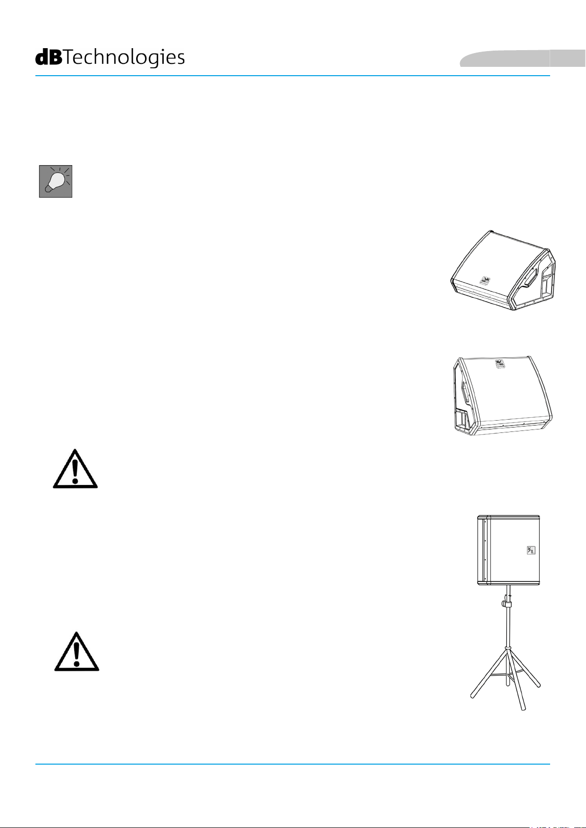
3. EJEMPLOS DE USO
• En conguración monitor, planear la instalación de manera que la
distribución acústica resulte adecuada, la cantidad de obstáculos sea mínima
y se evite el efecto Larsen (realimentación acústica).
USO EN EL SUELO COMO MONITOR DE ESCENA
El uso como monitor audio de escena es fácil y rápido. Comprobar que el suelo no
tenga una inclinación excesiva, que pueda causar el deslizamiento del monitor.
Prestar especial atención a la presencia de obstáculos delante del altavoz. Recordar
el patrón de dispersión presentado en la sección DISTRIBUCIÓN DEL SONIDO.
Español
USO COMO MONITOR PARA DISTANCIAS MAYORES
Mediante los pies del equipo, es posible apoyar el monitor en el lado del disipador
del amplicador como ilustra la gura. Así será posible utilizar el altavoz como
monitor con una cobertura frontal mayor en el escenario. Durante este uso
especíco, el disipador puede alcanzar temperaturas elevadas (supercie caliente).
¡ATENCIÓN!
• el disipador del difusor LVX XM puede alcanzar altas temperaturas.
Antes de utilizar el difusor en este tipo de instalación, comprobar
que el material de la supercie de apoyo sea resistente a las altas
temperaturas e impida la propagación del fuego.
INSTALACIÓN EN TRÍPODE
Gracias al adaptador para poste diámetro 35 mm, es posible montar el monitor en
un trípode. Comprobar que este soporte tenga el pie central hacia adelante, para
garantizar su estabilidad. La altura máxima permitida entre el suelo y la base del
monitor es de 1,4 m.
¡ATENCIÓN!
• En contextos de uso al aire libre, si fuera necesario, asegurar el
difusor para evitar que oscile debido a agentes atmosféricos o
viento.
• Utilizar un soporte de dimensiones idóneas, con el pie central
hacia adelante para garantizar una estabilidad adecuada.
• No utilizar nunca las asas para colgar el difusor.
• Las únicas conguraciones admisibles son las ilustradas en este
manual
LVX XM15 Cod. 420120241 REV.1.0
86
Page 87

Español
4. ACTUALIZACIÓN DEL FIRMWARE
ES muy importante mantener actualizado el rmware del producto, para garantizar su funcionalidad completa.
Controlar periódicamente la página web http://www.dbtechnologies.com en la sección “DOWNLOADS”.
1. Descargar USB BURNER MANAGER en la sección “SOFTWARE & CONTROLLER” del sitio web dBTechnologies.
2. Descargar el archivo .zip del último rmware en la sección “DOWNLOADS” relativa al propio producto
3. Conectar el producto al PC mediante un cable USB (no proporcionado) con el conector del tipo correcto (ver
este detalle en el capítulo CARACTERÍSTICAS DE LA SECCIÓN DE AMPLIFICACIÓN Y CONTROL)
4. En la pantalla del USB BURNER MANAGER, en la parte superior derecha, seleccionar “File Opening”.
5. Seleccionar el archivo del rmware descargado anteriormente (comprobando que sea la versión correcta para
el sistema operativo).
6. Efectuar las operaciones ilustradas en la pantalla.
7. Hacer clic en UPDATE.
LVX XM15 Cod. 420120241 REV.1.0
87
Page 88

5. ACCESSORIOS
Para un montaje rápido como sistema PA, está disponible como accesorio:
• SSB2, par de trípodes diámetro 35 mm, útiles para el montaje de 2 LVX XM15 en caso de empleo como
sistema de refuerzo de sonido PA. En el lado del monitor, integrado en su bastidor, está presente un
adaptador pole mount especíco para este uso.
Español
Para más información, consultar el manual del producto.
LVX XM15 Cod. 420120241 REV.1.0
88
Page 89

Español
6. RESOLUCIÓN DE PROBLEMAS
El difusor no se enciende:
1. Comprobar la presencia correcta de la alimentación general del sistema.
2. Comprobar que el cable de alimentación con conector POWERCON esté conectado correctamente.
3. Si el problema persiste, contactar con la asistencia.
El difusor se enciende pero no emite sonidos:
1. Comprobar que las conexiones de entrada de la señal de audio sean correctas, preferentemente con
cables con conectores Neutrik®.
2. Comprobar que los cables utilizados no estén dañados.
3. Comprobar que el mixer o la fuente de audio esté encendido y muestre claramente la presencia de una
señal de salida.
4. Comprobar que el nivel de Audio Input Sensitivity (3) en el panel de control del amplicador sea
correcto.
El difusor emite un sonido distorsionado:
1. Con el sistema encendido, ajustar primero el volumen de la fuente, luego congurar el valor más
adecuado con el mando rotary Audio Input Sensitivity. Controlar si el LED de LIMITER está encendido,
porque indica que el sistema funciona en condiciones de distorsión.
2. Comprobar que los cables utilizados no estén dañados, y sustituirlos si es necesario (un cable dañado
puede causar una pérdida o alteración de la señal).
3. Comprobar que el control LINE-MIC corresponda al tipo de entrada conectada.
4. Controlar los parámetros del mando rotary DSP preset que inuyen en la respuesta en frecuencia de
salida. A tal efecto, consultar la sección PRIMER ENCENDIDO.
El monitoring en la escena no es suciente
1. Comprobar que el posicionamiento en el escenario sea correcto, de acuerdo con el patrón de dispersión
acústica indicado y con los tipos de posiciones ilustradas en la sección EJEMPLOS DE INSTALACIÓN.
2. Comprobar que no haya obstáculos directos entre el artista y su monitor.
3. Asegurarse de que el número de LVX XM15 utilizados sea suciente.
LVX XM15 Cod. 420120241 REV.1.0
89
Page 90

7. ESPECIFICACIONES TÉCNICAS
GENERAL
Español
Tipo:
DATOS ACÚSTICOSI
Respuesta en frecuencia [-6dB]:
Max SPL (@ 1m):
HF compression driver (salida):
HF Voice Coil:
Conguración acústica:
Frecuencia de crossover:
Cobertura (HxV):
LF:
Monitor coaxial activo de 2 vías para uso profesional
58 – 17800 Hz
128 dB
1”
1.4”
Reex
1700 Hz
90° x 70°
15”
LF Voice coil:
2.5”
AMPLIFICADOR
Tipo:
Clase de amplicación:
Potencia de pico:
Potencia de amplicación RMS:
LVX XM15 Cod. 420120241 REV.1.0
90
Digipro® G3
Clase D
1200 W
600 W
Page 91

Español
PROCESADOR
Regulador interior:
Convertidor A/D D/A:
Limitador:
DSP 56 bit
28/56 bit/48 kHz
Peak, RMS, Térmico
INTERFAZ DEL USUARIO
Wedge: [1] FLAT/ [2] VOCAL/ [3] HPF-80Hz/ [4] HPF-120Hz/
Ecualizaciones prejadas ():
Altavoz: [6] HF reduction/ [7] HF boost/ [8] loudness
Controles: Mando rotary BCD 8 Pos, MIC LINE SWITCH
[5] Service
I/O
Entradas: COMBO XLR, JACK 6,3 mm
Salidas:
USB:
1x XLR link OUT
Mini USB de tipo B
ESPECIFICACIONES DE ALIMENTACIÓN (ABSORCIÓN)
Absorción a 1/8 de la potencia en
condiciones medias de utilización (*):
Absorción a 1/3 de la potencia en
condiciones máximas de utilización
(**):
Absorción con altavoz encendido
faltando la señal (idle):
Corriente inicial de arranque (inrush
current):
Corriente y potencia totales
admisibles en un sistema con
alimentación transmitida:
* NOTAS PARA EL INSTALADOR: Valores referidos a 1/8 de la potencia, en condiciones medias de funcionamiento (programa musical
con clipping escaso o ausente). Se recomienda para cualquier clase de conguración que se les considere los valores mínimos de
dimensionamiento.
** NOTAS PARA EL INSTALADOR: Valores referidos a 1/3 de la potencia, en condiciones pesadas de funcionamiento (programa musical con
clipping frecuente e intervención del limitador). Se aconseja el dimensionamiento según sean estos valores en caso de instalaciones e tour
profesionales.
LVX XM15 Cod. 420120241 REV.1.0
1,01 A / 110 W (230 V) - 1,71 A / 113 W (115 V)
1,89 A / 230 W (230 V) - 3,2 A / 230 W (115 V)
19 W
27.3 A
14 A - 3200 W max / 11 A - 1200 W max
91
Page 92

DIMENSIONES
Español
Material:
Rejilla:
Posibilidad para y-bar:
Asas:
Montaje en poste: Sì, 36 mm
Ancho:
Altura:
Profundidad:
Peso:
Madera con recubrimiento de PVC
Pintada / procesado CNC
No
Integradas
640 mm
460 mm
370 mm
22,3 kg
LVX XM15 Cod. 420120241 REV.1.0
92
Page 93

Español
Características, especicaciones y aspecto de los productos pueden cambiar sin previo aviso. dBTechnologies
se reserva el derecho de modicar o mejorar el diseño o la fabricación sin asumir la obligación de modicar o
mejorar también los productos realizados anteriormente.
A.E.B. Industriale Srl
Via Brodolini, 8
Località Crespellano
40053 VALSAMOGGIA
BOLOGNA (ITALIA)
Tel +39 051 969870
Fax +39 051 969725
www.dbtechnologies.com
info@dbtechnologies-aeb.com
LVX XM15 Cod. 420120241 REV.1.0
93
 Loading...