

Page 1

Addendum To:
Wireless Temperature Station
Installation Manual
Changes Covered In This Addendum
• The temperature sensor is now shipped separately and must be connected to the Wireless Temperature Station during the installation.
• This station requir es a few additional steps when you ar e set ting t he console/receiver(s) transmitte r ID.
Temperature Sensor Connections
Please refer to the following instructions when you are preparing the Wireless
Temperature Station for ins talla tion. Plea se pe rfor m th ese steps just before you
install the 3-volt lithium battery, Page 3 in the Wireless Temperature Station
Installation Manual.
1. Open the station housing.
2. Take square rubber grommet from the right side on the bottom of the st ation housing
3. Run the temperature sensor cable through it.
When you reinstall the grommet, be sure the connector end of the sensor
cable is located on the inside of the housing. You’ll need at least
4. Install the grommet back into the slot in the station housing with the sen-
sor cable connector , adjusting the inside cable length as need ed for a
tidy installation.
5. Refer to the illustration and connect the temperature sensor cable to the
modular connector labeled TEMP/HUM.
6. Use the small, 4 inch (100 mm) cable tie provided with your station to
secure the sensor cable to the cable tie mount.
The cable tie will provide strain relief for the sensor cable connection.
7. Continue with the installation as described in the Wireless Temperature
Station Installation Manual, starting with Setting the Transmitter ID on
page 4.
Product # 6370
Page 2
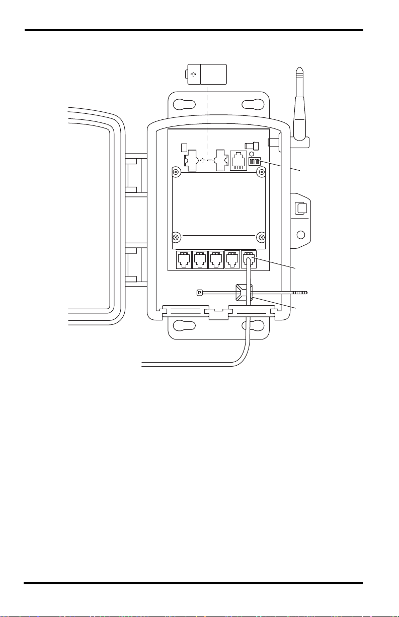
3-Volt Lithium Battery
Transmitter
ID Switches
Temperature Sensor Cable
Temperature Sensor Cable Installation
UV SUN RAIN WIND
UV SUN RAIN WIND
TEMP
HUM
Temperature
Sensor Cable
Connection
Cable Tie
Cable Tie
Mount
Page 2 Installation Manual
Page 3

Setting Console/Receiver(s) to Same ID
Use this procedure instead of the one found at the top of page 5 in the Installation Manual.
Identify the Fi rmware Date on the Vantage Pro Console
1. Press and hold the DONE key and press the “+” (up arrow) key at the
same time.
The firmware rev and date will scroll across the bottom of the LCD screen.
2. Write the firmware date down: ________________________________
Setting the Vantage Pro Consol e
1. Put your console into Setup Mode — press and hold the DONE key and
press the “-” (down arrow) key.
The console will show you Screen 1: Transmitters. You should see the
words: “RECEIVING FROM...” and “STATION N O.” follo wed by the tr ansmitter IDs that your console detects. One of these should be the ID number
you just set on the temperature station transmitter. If you don’t see it, make
sure the console is within 10' of the transmitter, and verify that you set the
DIP switches correctly. If you still don’t see it, refer to the “TEST mode” section on page 6 of the Installation Manual.
2. Press the DONE key to move on to Screen 2: Selecting Transmitters.
Setup Mode – Screen 2 is wher e you will set the console to r ecogni ze signals
on the selected ID as coming from a temperature stat ion.
3. Press the LEFT or RIGHT arrow key, or the STATION key, to scroll
through transmitter IDs.
When you see the ID you chose for the temperature station, use the “+” ( up
arrow) or “-” (down arrow) keys to activate reception of that ID code. Make
sure the screen shows “ON”.
4. Press the GRAPH key to cha nge the typ e o f station a ssigned to that transmitter ID.
Press the GRAPH key until the word “TEMP” appears.
5. For firmware dated before January 2003: If you don’t see a “4X” next to
the station type, press the HI/LOW key once.
A “4X” should appear next to the stat ion type.
6. For firmware dated January 2003 or later: If you don’t see a “4X” next to
the station type, Press and hold the TEMP key then press the HI/LOW
key once.
A “4X” should appear next to the stat ion type.
7. To exit Setup Mode, press and hold the DONE key.
8. Continue with the installation as described in the Wireless Temperature
Station Installation Manual, starting with Viewing Current Temperature
on page 5.
Setting Console/Receiver(s) to Same ID Page 3
Page 4

FCC Part 15 Class B Registration Warning
This equipment has been tested and found to comply with the limits for a class B digital
device, pursuant to Part 15 of the FCC Rules. These limits are designed to provide reasonable
protection ag a inst harmful interference in a residential installati on. This equipment generates,
uses and can radiate radio frequency energy and, if not installed and used in accordance with
the instructions, may cause harmful interference to radio communications. However, there is
no guarantee that interferenc e wil l n ot occ ur in a p art icular installation.
If this equipment does cause harmful interference to radio or television reception, which can
be determined by turning the equipment o f f and on, the user is enco uraged to try t o corr ect th e
interference by one or more of the following measures:
• Reorient or relocate the receiving antenna.
• Increase the separation between the equipment and receiver.
• Connect the equipment into an outlet on a circuit different from that to
which the receiver is connected.
• Consult the dealer or an experienced radio/TV technician for help.
Changes or modifications not expressly approved in wri tin g by Da vis Instruments may void
the user’s authority to operate this equipment.
Product Numbers: 6370
Davis Instruments Part Number: 7395.139A
Wireless Temperature Station Installation Manual Addendum
Rev. B Manual (04/28/03)
This product complies with the essential protection requirements of the EC EMC Directve 89/336/EC.
Copyright ©2003 Davis Instruments Corp. All rights reserved.
Vantage Pro is a registered trademark of Davis Instruments Corporation.
3465 Diablo Avenue, Hayward, CA 94545-2778 U.S.A.
510-732-9229 • Fax: 510-732-9188
E-mail: info@davisnet.com • www.davisnet.com
 Loading...