

Page 1
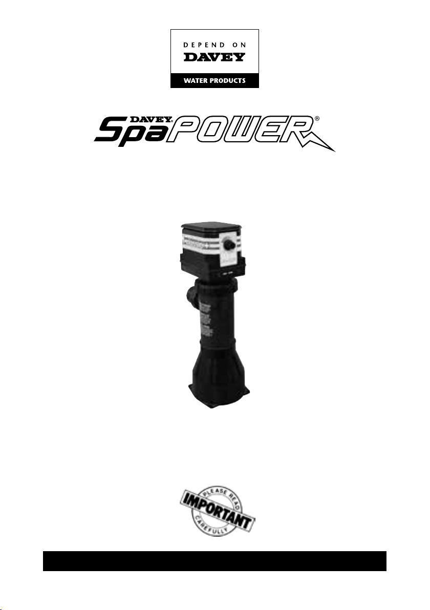
Classic Heater
Pool Controller
Installation and
Operating Instructions
Please pass these instructions on to the operator of this equipment.
Page 2

INSTALLATIONS INSTRUCTIONS — PLEASE READ CAREFULLY
GENERAL
The spa heater is the rst of a new generation of heaters that have been totally
redesigned to incorporate all the latest concepts in safe water heating. The heater
is reliable, easy to install, simple to operate and easy to maintain. It includes all its
own control and safety devices. It is designed to look after itself.
All the control system of the spa pack has to do is turn on the pump. The heater
detects the water pressure change and operates accordingly.
INSTALLATION
Before planning any installation please note the following:
1. The heater power supply is not controlled by the spa control box.
2. Heaters up to 2.4kW are normally used for portable spa pools and thus the
heater is provided with a 3 pin socket to permit the connection of a suitable
control box directly to the heater without additional wiring.
3. It is strongly recommended that the supply of all spa installations be protected
by an EARTH LEAKAGE CIRCUIT BREAKER [ELCB] [RCD] preferably tted at
the switchboard.
4. All installations must comply with AS3000 and the special requirements of
section 6 and any additional requirements of your local supply authority bylaws.
PHYSICAL LOCATION
The heater should be located in the spa system as follows:
1. On the pressure side of the pump.
2. Before the lter in the return line.
3. Where it is accessible for maintenance with enough clear room to remove
control head from heater body.
4. In a vertical position, or if horizontal, so that the side port faces down.
5. It is recommended that the Classic Spa Heater water inlet is set to the higher
port. If for installation reasons this is not possible, the lower port can be used for
water inlet as the Classic Spa Heater inlet / outlet ports can be interchanged.
6. Level — denitely not plumbed at an angle.
7. Protected from rain, water splashes, hosing etc.
8. In an ambient temperature not exceeding 55°C.
Where the heater is being installed in a position exposed to the weather,
splashing and the like, it must be protected by an additional enclosure
having a degree of protection to IP24-AS1939.
2
Page 3
WIRING
ALL FIXED ELECTRICAL WIRING MUST BE COMPLETED BY A SUITABLY
QUALIFIED PERSON.
1. Check the kilowatt rating of the heater. Ensure the correct size cable is being
used.
2. The cable entry point is via one of three knockouts provided on the underside of
the heater head. Use the correct size grommets and conduits when installing.
3. Check that wiring to terminal blocks is secured rmly and to the correct
terminals.
PLUMBING
1. The heater body may be plumbed so the water ow can be in either direction.
The head of the heater may be turned to any of the four keyed directions (90°) to
give best access to the thermostat control.
2. When installing the heater head the ‘O’ ring must be carefully
located on the element carrier and NOT in the body. When tting
head make sure the ‘O’ ring doesn’t become dislodged and fall
into the body. To assist assembly it is recommended that a light
lubricant be used on the inside of the body barrel to help the
components to slide together easily. REFER FIG.2 & 3.
3. When connecting pipework to heater make sure the ‘O’ rings are properly seated
in the mac union tting. NB. Hand tighten only. Using tools will distort the ttings.
4. Make sure the heater is mounted on its stand or secured rmly so that vibration
is minimised.
5. It is recommended that the pipework has shut off valves so the heater head can
be removed for service without loss of water or downtime due to reheating.
3
Page 4

TESTING (MUST BE COMPLETED BY QUALIFIED PERSONNEL)
1. Double check that all plumbing is connected correctly and that the supply is
available for heater and control box.
2. Before switch on check that gate valves (if tted) are open and the thermostat is
turned fully anti clockwise.
3. The heater lid should be off for setting up pressure switch adjustment.
4. Apply a voltmeter, neon indicator or such test device at element terminal or
control relay. If preferred, a current meter could be used.
5. Apply power. There should be no indication that the element is alive.
6. Start pump and check for water leaks, paying particular attention to the join
between heating head and body.
7. After checking the system is free of plumbing problems, allowing sufcient time
for all air to be purged, advance the thermostat setting to full on.
8. The test device should now indicate heating. Turning the thermostat control
through its full range should switch test indicators on and off.
9. Leave the thermostat setting at the fully clockwise position so the test indicator
is active and stop the pump. The indicator should switch off almost immediately.
If it fails to switch off restart pump quickly and adjust the screw on the pressure
switch clockwise until heating stops. Adjust back until heating restarts and then
one further full turn.
the heating is switching on and off consistent with the pump running.
REFER FIG 1.
N.B. If the heater is tted to a portable pool or the equipment is
mounted at about the same level as the pool water the pressure
switch will probably not require adjustment. CHECK IT ANYWAY.
It the equipment is mounted nelow the level of the pool water
the static water pressure could be enough to hold the heating
on after the pump stops. It is important for safety that this
condition does not occur. FAILURE TO SET THE PRESSURE
SWITCH CORRECTLY WILL VOID THE WARRANTY.
Stop/start pump several times until you are happy that
4
Page 5

Turn the screw clockwise if the
pressure holds heating element
on. Turn anticlockwise if the
pressure is insufcient to operate
the heater.
The above adjustments can only
be done if the pool is below the
thermostat setting.
The ‘O’ ring must be tted to the
control head against the
retaining edge before tting
to heater body. Do not rely on
locking ring to pull head and
body together. Use downward
pressure while tightening locking
ring, making sure that locators
engage correctly.
Hand tighten only.
DO NOT assemble heater with
‘O’ ring as shown. This will
dislodge when head and body
are engaged causing water
damage to the electronics.
However, lightly lubricating the
inside of this lip is permissible &
will help assembly.
5
Page 6

NOTES
6
Page 7

Davey® Repair or Replacement Guarantee
In the unlikely event in Australia or New Zealand that this Davey product develops any malfunction
within two years of the date of original purchase due to faulty materials or manufacture, Davey will at
our option repair or replace it for you free of charge, subject to the conditions below.
Should you experience any difculties with your Davey product, we suggest in the rst instance that
you contact the Davey Dealer from which you purchased the Davey product. Alternatively you can
phone our Customer Service line on 1300 367 866 in Australia, or 0800 654 333 in New Zealand, or
send a written letter to Davey at the address listed below. On receipt of your claim, Davey will seek to
resolve your difculties or, if the product is faulty or defective, advise you on how to have your Davey
product repaired, obtain a replacement or a refund.
Your Davey Two Year Guarantee naturally does not cover normal wear or tear, replacement of product
consumables (i.e. mechanical seals, bearings or capacitors), loss or damage resulting from misuse
or negligent handling, improper use for which the product was not designed or advertised, failure to
properly follow the provided installation and operating instructions, failure to carry out maintenance,
corrosive or abrasive water or other liquid, lightning or high voltage spikes, or unauthorized persons
attempting repairs. Where applicable, your Davey product must only be connected to the voltage
shown on the nameplate.
Your Davey Two Year Guarantee does not cover freight or any other costs incurred in making a claim.
Please retain your receipt as proof of purchase; you MUST provide evidence of the date of original
purchase when claiming under the Davey Two Year Guarantee.
Davey shall not be liable for any loss of prots or any consequential, indirect or special loss, damage
or injury of any kind whatsoever arising directly or indirectly from Davey products. This limitation
does not apply to any liability of Davey for failure to comply with a consumer guarantee applicable to
your Davey product under the Australian or New Zealand legislation and does not affect any rights or
remedies that may be available to you under the Australian or New Zealand Consumer Legislation.
In Australia, you are entitled to a replacement or refund for a major failure and for compensation for
any other reasonably foreseeable loss or damage. You are also entitled to have the goods repaired
or replaced if the goods fail to be of acceptable quality and the failure does not amount to a major
failure.
Should your Davey product require repair or service after the guarantee period; contact your nearest
Davey Dealer or phone the Davey Support Centre on the number listed below.
For a complete list of Davey Dealers visit our website (davey.com.au) or call:
AUSTRALIA
Davey Support Centre
6 Lakeview Drive,
Scoresby, Australia 3179
Ph: 1300 367 866
Fax: 1300 369 119
Website: davey.com.au
Davey Water Products Pty Ltd
Member of the GUD Group
ABN 18 066 327 517
® Davey is a registered trade mark of Davey Water Products Pty Ltd.
© Davey Water Products Pty Ltd 2013.
* Installation and operating instructions are included with the product when purchased new.
They may also be found on our website.
NEW ZEALAND
Davey Support Centre
7 Rockridge Avenue,
Penrose, Auckland 1061
Ph: 0800 654 333
Fax: 09 527 7654
Website: daveynz.co.nz
7
Page 8

AUSTRALIA
Davey Support Centre
6 Lakeview Drive,
Scoresby, Australia 3179
Ph: 1300 367 866
Fax: 1300 369 119
Website: davey.com.au
Davey Water Products Pty Ltd
Member of the GUD Group
ABN 18 066 327 517
® Davey is a registered trade mark of Davey Water Products Pty Ltd.
© Davey Water Products Pty Ltd 2013.
NEW ZEALAND
Davey Support Centre
7 Rockridge Avenue,
Penrose, Auckland 1061
Ph: 0800 654 333
Fax: 09 527 7654
Website: daveynz.co.nz
P/N Q916546-4 supersedes P/N Q916546-3
 Loading...