

Davey SilensorPRO SP200BT, SilensorPRO SP400BT Installation And Operating Instructions Manual
Page 1
SilensorPRO SP200BT & SP400BT
Swimming Pool Pump
Installation and Operating
Instructions
50/60Hz
SP200BT
SP400BT
UK - Installation and Operating Instructions 1-20
DE - Installations- und Betriebs-anleitung 21-40
IT - Istruzioni di montaggio e di utilizzo 41-60
NL - Installatie- en gebruiksinstructies 61-80
PT - Instruções de Instalação e Funcionamento 81-100
ES- Instalación e instrucciones de funcionamiento 101-120
FR - Instructions d’installation et d’utilisation 121-140
Please refer to the Davey website in your region as per back page of this
document for any product information updates.
Please pass these instructions on to the operator of this equipment.
English
Page 2

Congratulations on your purchase of a high quality, SilensorPRO SP200BT, or SP400BT pump. All
components have been designed and manufactured to give trouble free, reliable operation.
Table of Contents:
1. INSTALLATION OF THE DAVEY VARIABLE SPEED PUMP .....................................................................3
Power connection .......................................................................................................................................3
Pipe connection ..........................................................................................................................................4
2. TYPICAL INSTALLATION DIAGRAM .........................................................................................................5
3. PERFORMANCE SPECIFICATIONS .........................................................................................................5
3.1 SP200BT Hydraulic Performance .........................................................................................................5
3.2 SP200BT Electrical Specifications ........................................................................................................6
3.3 SP400BT Hydraulic Performance .........................................................................................................6
3.4 SP400BT Electrical Specifications ........................................................................................................6
4. OWNERS MANUAL ....................................................................................................................................7
Saving energy with your SilensorPRO ........................................................................................................7
Pre-start up checklist ..................................................................................................................................7
Low energy operation .................................................................................................................................8
Guidelines for recommended pump operating hours ..................................................................................8
Emptying the strainer basket ......................................................................................................................9
Routine maintenance ..................................................................................................................................9
5. FEATURES & FUNCTIONALITY ..............................................................................................................10
Multi-Coloured LED indicator light ............................................................................................................10
Backwash Speed Cycling Technology ......................................................................................................10
Full variable frequency drive with user friendly selectable speed dial ......................................................10
Large 4.5 litre lint pot ................................................................................................................................10
Patented water-cooled design for smooth and super quiet operation ......................................................10
SP400BT constant flow/speed compensation ..........................................................................................10
SP400BT weatherproof RJ45 Communication Port (see section 7 for connection details) ......................10
6. BLUETOOTH FUNCTIONALITY ..............................................................................................................11
Bluetooth App Set Up ...............................................................................................................................11
Pairing a device to the pump ....................................................................................................................11
External Timer / Chlorinator ......................................................................................................................11
Schedule mode ......................................................................................................................................... 11
Setting a schedule ....................................................................................................................................12
Settings .....................................................................................................................................................12
Priming speed / Max speed ......................................................................................................................12
Backwash..................................................................................................................................................13
External time present ................................................................................................................................13
Disconnect function ..................................................................................................................................13
Factory reset .............................................................................................................................................13
Pump fault finding .....................................................................................................................................13
7. ADVANCED SETUP OF SP400BT ...........................................................................................................14
External AUX connections overview .........................................................................................................14
Digital control inputs .................................................................................................................................15
Interfacing equipment to the SilensorPRO SP400BT ...............................................................................15
Analogue control inputs ............................................................................................................................16
8. TECHNICAL SPECIFICATIONS ...............................................................................................................16
9. USING YOUR SILENSORPRO WITH A SALT WATER CHLORINATOR .................................................17
10. OPERATING YOUR SUCTION POOL CLEANER ....................................................................................17
11. TROUBLE SHOOTING .............................................................................................................................18
12. REMOVAL OF THE SILENSORPRO FROM PIPEWORK ........................................................................18
13. WATER QUALITY .....................................................................................................................................18
14. DAVEY WARRANTY .................................................................................................................................20
English
2
Page 3
1. INSTALLATION OF THE DAVEY VARIABLE SPEED PUMP
The SilensorPRO should be located as close to the water as practicable and mounted on a firm base in a
well drained position, high enough to prevent any flooding. It is the installer/owner’s responsibility to locate
the pump such that the nameplate can be easily read and the SilensorPRO can be readily accessed for
service. It is recommended that the SilensorPRO is protected from the weather. Enclosures should be
ventilated to prevent condensation build-up.
Failure to follow these instructions and comply with all applicable codes may cause
serious bodily injury and/or property damage.
This pump requires professional expertise for installation and maintenance. The
installation of this product should be carried out by a person knowledgeable in
swimming pool plumbing requirements and who follows the installation instructions
provided in this manual.
Power connection
IMPORTANT INFORMATION Your SilensorPRO is double insulated to water circuit.
If equipotential bonding structure is required, then an Equipotential Bonding Point
is provided. (Please refer to your local statutes and/or regulations for AS/NZ 3000
equivalent wiring standards).
CAUTION! In the interest of safety, we advise that all brands and types of pool pumps
must be installed in accordance with AS/NZS 3000, known as the national wiring
rules, or equivalent local standards. All electrical installations must be carried out by
a qualied electrician. Davey recommends that all installations are tted with earth
leakage, or residual current protection devices. Rated residual operating current not
exceeding 30mA.
WARNING! Ensure that an electrical isolation switch is located with easy access so that
the pump can be switched off in an emergency.
F NFC C 15-100 GB BS7671:1992
D DIN VDE 0100-702 EW EVHS-HD 384-7-702
A OVE 8001-4-702 H MSZ 2364-702:1994/MSZ 10-533 1/1990
E UNE 20460-7-702 1993, REBT ITC-BT-31 2002 M MSA HD 384-7-702.S2
IRL IS HD 384-7-702 PL PN-IEC 60364-7-702: 1999
I CEI 64-8/7 CZ CSN 33 2000 7-702
LUX 384-7.702 S2 SK STN 33 2000-7-702
NL NEN 1010-7.702 SLO SIST HD 384-7-702.S2
The SilensorPRO is suitable for connection to a nominal 220 – 240 volt 50/60Hz power supply and is
equipped with a flex cord. If a power outlet is not available within 3 metres of the pump, a 3-pin power point
in a safe, dry place may need to be provided by an electrician. Extension cords are unsafe around pools and
should be avoided. If the supply cord of the SilensorPRO is damaged it must be replaced by Davey, or an
approved agent with genuine Davey spares.
The SilensorPRO incorporates motor overload detection designed to protect the motor from overheating.
If the motor gets too hot during operation, its operating speed will reduce to bring it within an acceptable
operating temperature and then will speed up to the originally set speed.
To reset the motor, switch the power off for 30 seconds, and then return the power from the mains switch.
English
3
Page 4
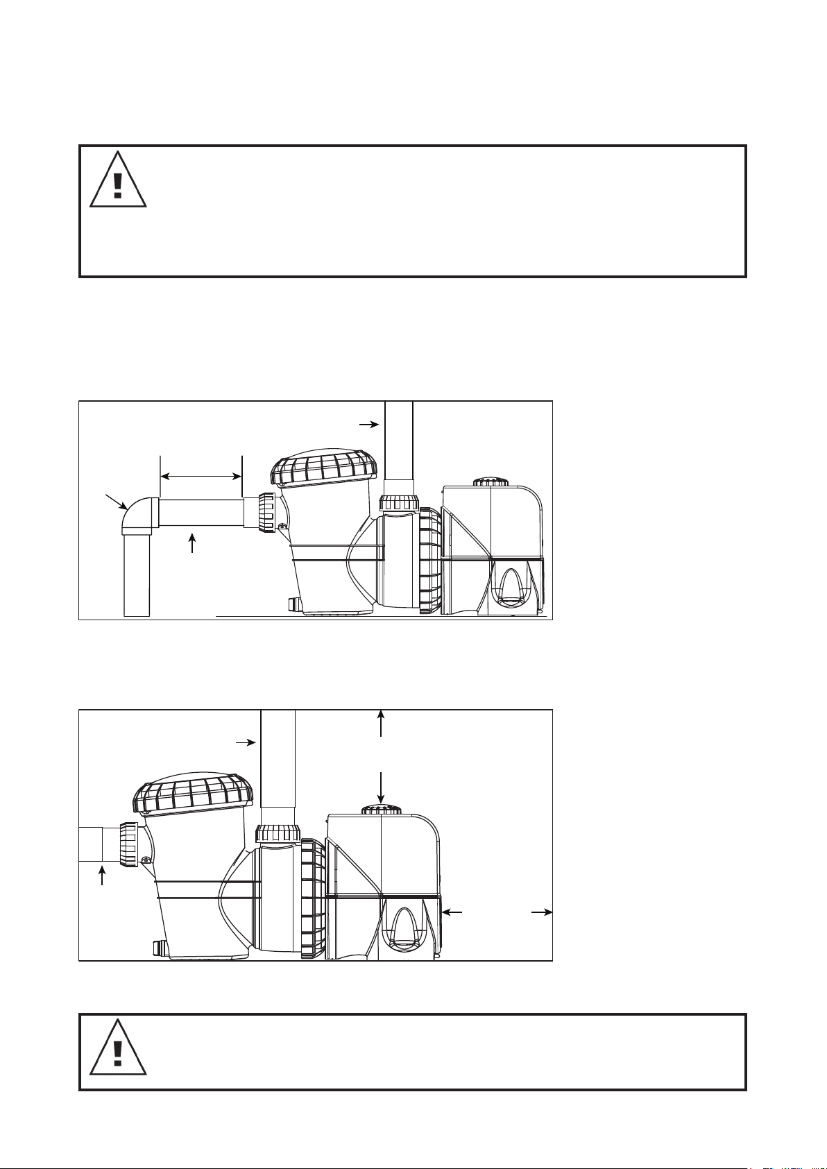
Pipe connection
Figure 1.2
152mm
MINIMUM
76mm
MINIMUM
Suction line
50/63mm
Return to
Pool
50/63mm
Return to
Barrel unions are provided for connecting to the piping from the pool. The pumps are designed to accept
50/63mm PVC fittings.
IMPORTANT INFORMATION If the SilensorPRO and lter are located below pool water
level, it is necessary to t isolating valves in the pipe between the pump and skimmer
box and in return pipe from the lter to the pool. When plumbing the discharge pipe,
ensure that the pipework does not interfere with the pumps speed dial. Barrel unions
need to be hand tightened. No sealant, glues or silicones are required.
The ttings on the SilensorPRO are constructed of ABS. Some PVC jointing compounds
are incompatible with ABS. Check compound suitability before use.
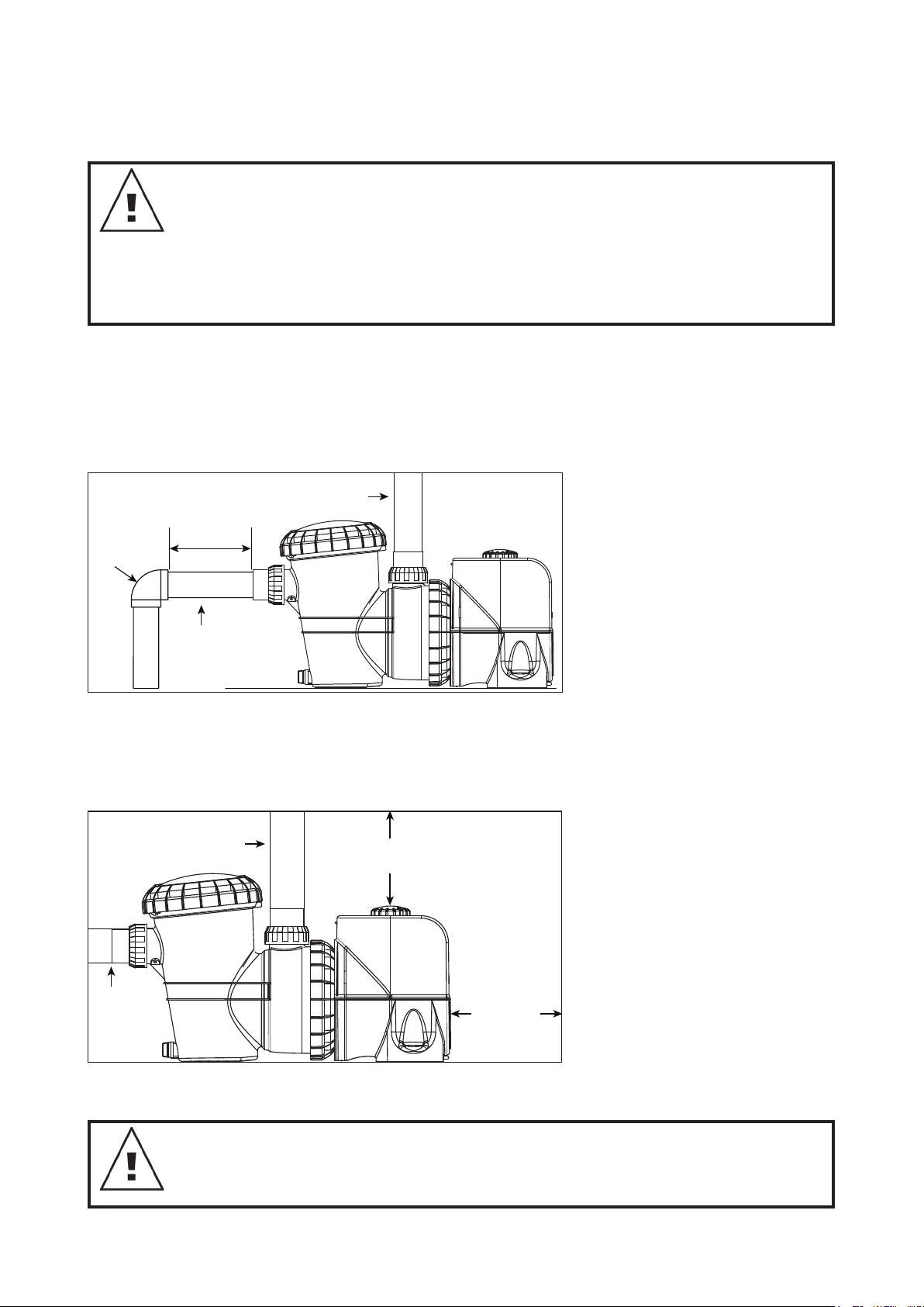
The use of any pipe smaller than those specified above is not recommended. Suction piping should be free
from all air leaks and any humps and hollows which cause suction difficulties. To achieve best efficiency, the
SilensorPRO should be installed such that turbulent water is limited as much as possible. As shown in figure
1.1, do not install a 90° elbow closer that 250mm from the inlet barrel union. Isolation valves used where
equipment is located below pool water level, should also be installed no closer than 250mm from inlet barrel
union. This will assist laminar flow.
ELBOW
The discharge piping from the SilensorPRO outlet should be connected to the inlet connection on the
swimming pool filter (usually at the filter control valve). As shown in figure 1.2, ensure adequate clearance
above the pump to not interfere with the SilensorPRO speed dial. Use a check valve in the discharge line
when using this pump for any application where there is significant height to the plumbing after the pump.
Figure 1.1
Figure 1.2
250mm
Suction line
50/63mm
Return to
Pool
50/63mm
Pool
50/63mm
152mm
MINIMUM
Suction line
50/63mm
76mm
MINIMUM
Be sure to install check valves when plumbing with another pump. This helps prevent reverse rotation of the
impeller and motor.
WARNING! Pump suction is hazardous and can trap and drown, or disembowel bathers.
Do not block suction. Do not operate swimming pools, spas, or spa baths if a suction
cover is broken, missing or loose. Two suction covers, or inlets must be provided into
every pump to avoid suction entrapment.
English
4
Page 5

2. TYPICAL INSTALLATION DIAGRAM
ProMaster - PM200SV
Performance
Pool pump Media Filter
3. PERFORMANCE SPECIFICATIONS
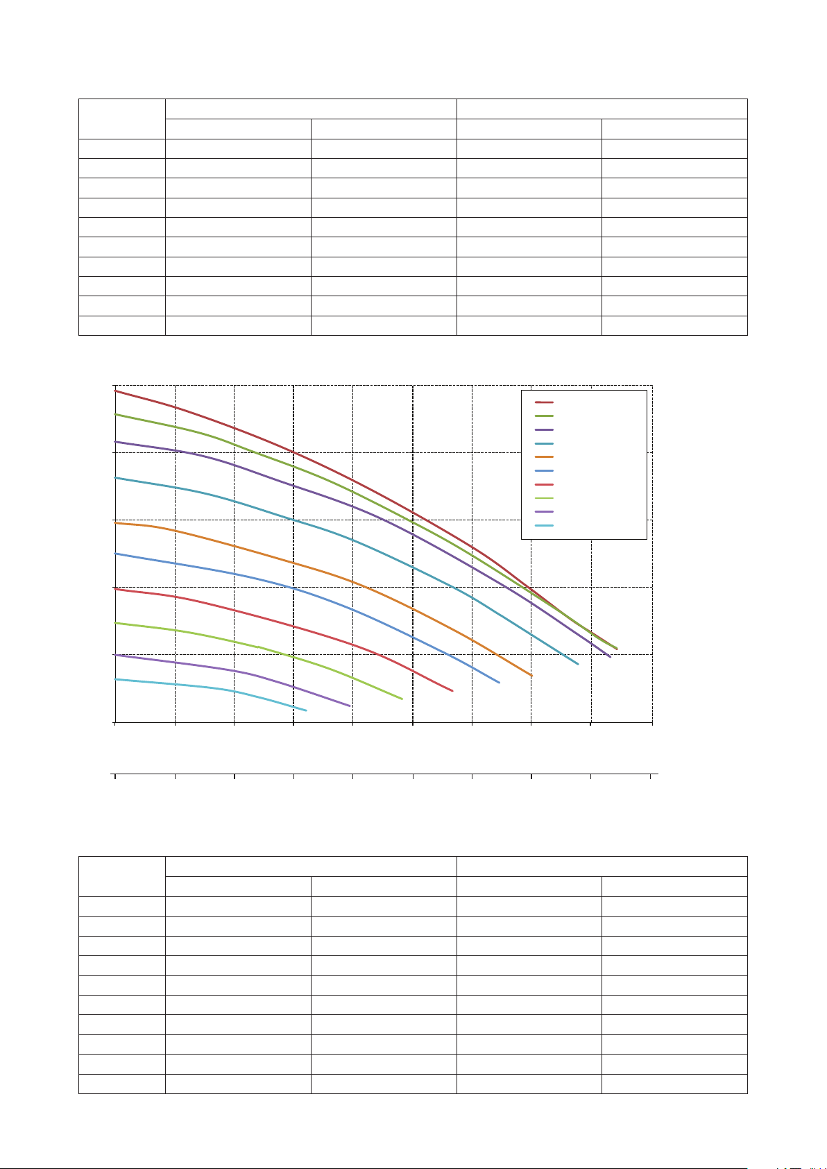
3.1 SP200BT hydraulic performance
25
20
15
Total Head ( m )
10
5
Dial position No. 10
Dial position No. 9
Dial position No. 8
Dial position No. 7
Dial position No. 6
Dial position No. 5
Dial position No. 4
Dial position No. 3
Dial position No. 2
Dial position No. 1
0
0 50 100 150 200 250 300 350 400
Flow ( lpm )
0
036 9 12 15 18 21 24
3
Flow ( m
5
/h )
English
Page 6

3.2 SP200BT electrical specifications
450
Speed
Setting
Dial 1 0.17 128 0.12 90
Dial 2 0.28 207 0.19 145
Dial 3 0.39 293 0.27 205
Dial 4 0.53 398 0.37 279
Dial 5 0.70 524 0.49 367
Dial 6 0.87 655 0.61 459
Dial 7 1.08 807 0.75 565
Dial 8 1.25 936 0.87 655
Dial 9 1.44 1,078 1.01 755
Dial 10 1.48 1,111 1.04 778
hp W hp W
Input Output
3.3 SP400BT hydraulic performance
25
Dial position No. 10
Dial position No. 9
Dial position No. 8
20
15
Dial position No. 7
Dial position No. 6
Dial position No. 5
Dial position No. 4
Dial position No. 3
Dial position No. 2
Dial position No. 1
Total Head ( m )
10
5
0
0 50 100 150 200 250 300 350 400
Flow ( lpm )
0
036 9 12 15 18 21 24 27
3
Flow ( m
/h )
3.4 SP400BT electrical specifications
Speed
Setting
Dial 1 0.17 126 0 .12 89
Dial 2 0.28 210 0.20 147
Dial 3 0.46 347 0.32 243
Dial 4 0.70 522 0.49 366
Dial 5 0.97 728 0.68 510
Dial 6 1.22 913 0.85 639
Dial 7 1.61 1, 211 1.13 848
Dial 8 1.97 1,478 1.38 1,034
Dial 9 2.18 1,635 1.59 1,191
Dial 10 2.19 1,639 1.62 1,212
hp W hp W
Input Output
English
6
Page 7

4. OWNERS MANUAL
This SilensorPRO is Bluetooth enabled, so you will be able to set and control the pump functions from your
smart device. Bluetooth is a wireless communication protocol that enables communication between devices.
This function is supported by any device that can download an app from IOS or Android App Store.
Read these instructions in their entirety before switching on this pump. If you are uncertain as to any of these
installation and operating instructions, please contact Davey as listed on the back of this document.
Every SilensorPRO is thoroughly water tested against a number of flow, pressure, voltage, current and
mechanical performance parameters. Davey’s advanced pump manufacturing technology provides reliable
and efficient pumping performance that lasts and lasts.
Saving energy with your SilensorPRO
The Davey variable speed pump is a super-efficient pump utilising a very clever, state of the art infinitely
variable AC motor that provides lower levels of noise, lower operating costs and lower greenhouse emissions
than traditional pool pumps.
Due to its ability to run at lower speeds than conventional pumps, your pump will also experience less
mechanical wear and tear due to less stress on the internal mechanical components. To achieve energy
efficient pumping is easy. Simply run the filtration pump at a lower speed but run it for longer than a
conventional fixed speed pump to “turn over” your pool water for adequate filtration and sanitisation. The
result is lower energy use and up to 70% lower operational costs.
The SilensorPRO has adjustable speed settings, so you can vary the speed you circulate your pool or spa
water at. Speeds can be adjusted to power a suction pool cleaner, in-floor cleaning system & pool heaters. A
backwash setting on the pump can be selected to backwash a media filter.
What to expect with the SilensorPRO (energy efficient operation) on your pool:
• If your SilensorPRO pump is replacing a traditional AC motor pump, you may will need to run it longer than
your old fixed speed pump. This is NORMAL and you will save energy when using lower speed settings.
• You may also notice that the pressure gauge on your filter is indicating a much lower pressure than you are
used to. This is also NORMAL. The lower system pressure is simply a result of the lower speed and flow
rate produced by the pump.
• While running at the lower speed settings you will also notice a significant reduction in pump noise. This is
a major benefit for you as it allows you to run your SilensorPRO during off peak electricity tariffs, which will
also assist in the reduction of your operating costs. Plus, you will also have much happier neighbours.
Many pool products rely on minimum flow rates for best operation and/or efficiency. If you are using low flow
settings on the SilensorPRO (e.g. speed 1 to 4) Davey recommends that you check the compatibility of the
speed or minimum flow rate required to run specific pool equipment such as:
• Suction pool cleaners;
• Ozone generators;
• Heating systems;
• Salt water chlorinator cells;
• In-floor pool cleaning systems.
Pre-start up checklist
• Speed setting chosen is a compatible setting with other pool equipment;
• The pump is installed in a safe and dry environment;
• The pump enclosure has adequate drainage in the event of leakage;
• Any transport plugs are removed;
• The pipe-work is correctly sealed and supported;
• The pump is primed correctly;
• The power supply is correctly connected;
• All steps have been taken for safe operation;
• The filter has been plumbed with 50/63mm pipe;
• The (app) schedule settings correspond with any other times in the system.
English
7
Page 8

Low energy operation
Your SilensorPRO SP200BT has speed settings from 1,500 - 3,600rpm. The SilensorPRO SP400BT has
speed settings from 1,050 - 3,100rpm. Speed 1 being the slowest and speed 10 being the fastest.
• Speed 1 provides the lowest speed and therefore the greatest energy efficiency and savings.
Operation
Backwashing your media filter
Pool Filtration
Suction pool cleaner operation
Manually cleaning your pool
Water Feature operation
Spa Jet operation
In-floor cleaning systems
Solar pool heating
Recommended Speed Setting
Backwash Speed
Speed 1 to 4
Speed 5 to 8
Speed 9 to 10
Guidelines for recommended pump operating hours
Typical residential pool turnover rate shall be a single turnover of the full volume of the pool water, within the
daily period that the pump would normally be operating. The table below provides a guide only to the running
times of your pump while in filtration mode in order to achieve the minimum turnover rate:
SilensorPRO SP200BT
Pool size
(Litres)
20,000 3.3 1.7 1.1
Speed 1 Speed 5 Speed 10
Speed Setting (hours)
30,000 5.0 2.5 1.7
40,000 6.7 3.3 2.2
50,000 8.3 4.2 2.8
60,000 10.0 5.0 3.3
80,000 13.3 6.7 4.4
100,000 16.7 8.3 5.6
SilensorPRO SP400BT
Pool size
(Litres)
20,000 2.4 1.3 0.9
30,000 3.7 2.0 1.4
40,000 4.9 2.7 1.9
50,000 6.1 3.3 2.3
60,000 7.4 4.0 2.8
80,000 9.8 5.3 3.8
100,000 12.3 6.7 4.7
Speed Setting (hours)
Speed 1 Speed 5 Speed 10
English
8
Page 9
In accordance with EN60335.1 we are obliged to inform you that this appliance can
be used by children aged from 8 years and above and persons with reduced physical
sensory, or mental capabilities, or lack of experience and knowledge, if they have been
given supervision, or instruction concerning use of the appliance in a safe way and
understand the hazards involved. Children should be supervised to ensure they do not
play with the appliance.
Emptying the strainer basket
The strainer basket should be inspected frequently through the transparent lid and emptied when a build-up
of rubbish is evident. The directions below should be followed.
• Switch off pump;
• Unscrew the strainer basket lid anti-clockwise and remove;
• Remove the strainer basket by lifting upwards from its housing;
• Empty the trapped refuse from the basket. Hose out with water if necessary.
NOTE: NEVER knock the plastic basket on a hard surface as it will cause damage.
• Check the strainer basket for cracks, replace the strainer basket in the pump if damaged;
• Replace the lid and ensure that it seals on the large rubber o-ring. Firm hand tightness only is required.
The o-ring & thread can be lubricated with Hydra Slip or equivalent products.
Failure to undertake regular maintenance may cause damage not covered by warranty.
Routine maintenance
To maximise the life of the SilensorPRO, and for personal safety use this checklist once a week. Ensure
pump is off before starting:
• Make sure that any pressure gauges are in working condition and the operating pressure is within limits as
specified on the product;
• Make sure that each suction inlet and main drain has a cover that is securely attached and in safe working
condition;
• Make sure that all skimmer covers are securely attached and in safe working condition. These should be
replaced every 3 to 4 years;
• Remove any obstructions or debris from the main drain cover;
• Ensure the skimmer and pump baskets are free of leaves and debris at least once a week;
• Remove obstructions and combustibles from around the pump motor;
• Make sure all wiring connections are clean and that all wiring and electrical equipment is in good condition.
Damaged wiring must be repaired or replaced by a qualified electrician as soon as damage is discovered;
• Check water balance and sanitizer levels at your local pool shop.
English
9
Page 10

5. FEATURES & FUNCTIONALITY
The SilensorPRO has several operational features. The following explain each of these.
Multi-coloured LED indicator light
Used for identifying required settings for programming time for full speed (Boost) cycling and warnings:
• Solid green = Normal dial operation
• Slow flashing green = In backwash mode
• Fast Flashing green = AUX external control
• Solid White = Time to Backwash
• Fast Flashing White = Fault detected - reset pump
• Slow Flashing blue = Operated by Bluetooth
• Solid blue = Bluetooth mode
Backwash speed cycling technology
When in backwash mode the SilensorPRO will cycle between a low and high speed to help agitate the filter
media for a more effective clean. This reduces wasted water and chemicals during the backwash cycling
process.
Full variable frequency drive with user friendly selectable speed dial
• Provides for easy selection of desired filtration speed
• No complicated digital push button controls
Large 4.5 litre lint pot
• Provides for longer intervals between cleaning
Patented water-cooled design for smooth and super quiet operation
The SilensorPRO has a water-cooled membrane and jacket around the motor which helps to keep the pump
cool during operation. Waste heat off the motor is transferred into the pool water, helping to reduce pool
heating energy costs.
SP400BT constant flow/speed compensation
As the pool filter becomes dirty, pressure builds up. With a typical pool pump, this would naturally slow the
flow coming through the system. The SilensorPRO has the intelligence to automatically detect the resistance
applied by a filter and slowly compensate the reduction flow, by increasing the speed of the motor. The result
is the flow remains constant between filter cleans.
When the SilensorPRO detects that the speed increase indicates time to backwash your filter, the LED
indicator will show a solid white display (see item above).
SP400BT weatherproof RJ45 communication port
(see section 7 for connection details)
• For communication and connecting to external pool control systems
• For receiving a signal from a heat pump, or gas heater to ramp the SilensorPRO speed to full during the
heating process
• Service diagnostics and software updates (For Davey use only)
10
English
Page 11

6. BLUETOOTH FUNCTIONALITY
Bluetooth app set up
• Open the “App Store” app that is available on your device.
• Search “Davey Pool Pump”
• Install the app on your device
The app can be installed on to as many devices as desired, however, only one device can control the pump
at any given time. The language and time of the app is the same as your device setting. The measuring units
are automatically defaulted to your device’s region units, however, you can choose between Litres, Gallons
3
/hr.
or m
Pairing a device to the pump
• Open app on your smart device.
• Turn dial on the pump from “off” to “Bluetooth”, you will see the LED flash white for a second.
• On your device, press the connect button.
• When setting up for the first time ONLY, select “YES” to allowing location.
• Please note that the first time the devices are paired, there is a 2-minute time limit to do so before the
procedure will have to be repeated.
External timer / chlorinator
A pop-up will appear asking if you are using an external timer, or
chlorinator to control the SilensorPRO. Please select “yes”, “no”.
This is a safety function that helps ensure the chlorinator only
runs when the pump is working.
This pop-up
will show
Note: App screenshots are for demonstration purposes only.
Actual screens may vary.
Manual, or scheduled mode
Two modes are available depending on whether you wish to
manually operate the SilensorPRO, or alternatively you can
create a schedule of operation.
Manual mode
• If in schedule mode, press “switch to manual mode”
• The app will now be in manual mode and you can manually
adjust the speed by pressing the (+/ -) buttons.
• In manual mode, the SilensorPRO will run at the set speed,
even if the phone is not in range.
• Anytime the dial is switched to the Bluetooth position, it will
run at the previous set speed after the priming cycle.
Schedule mode
• There are two options (set a daily cycle, or a weekly cycle) by
pressing the desired box.
• This option allows you to either create a standard “daily
schedule” which will consistently operate the set levels every day;
11
SilensorPro BT
To switch between
manual or schedule
mode you can press
this button.
English
Page 12
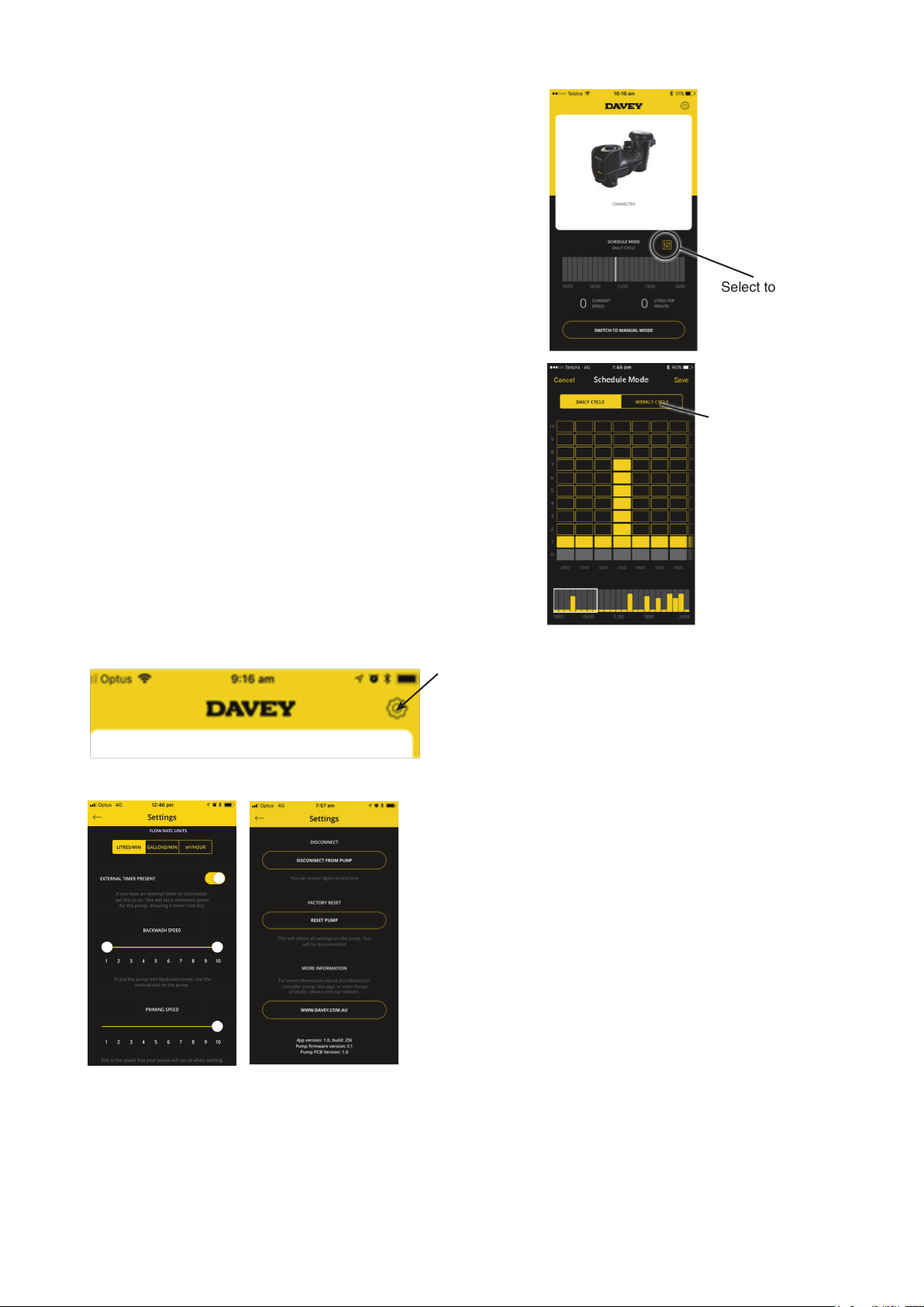
There are two options (set a daily cycle or a weekly cycle) by
pressing the desired box. This option allows you to either create
a standard “daily schedule” which will consistently operate the set
levels every day
• The “weekly cycle” option can be set for the entire week, giving
you the ability to alter daily pump cycles depending on the
weather, bather load etc.
Setting a schedule
SilensorPro BT
• Select the box which relates to the time that you require the
pump to operate;
• Select the speed setting you would like the pump to run at any
time. Note: Settings of the pump (1-10) refers to slowest to
fastest operating speed of the pump;
• Once you are happy with your schedule, select “Save”.
Communications between the device and the pump can take
up to 20 seconds depending on the schedule selected;
• The row at the bottom of the screen indicates a summary
of where the schedule is by day and by hour. This summary
screen can easily be altered by swiping up or down the
columns above;
• Note: If using a chlorinator, you must ensure that the “on”
times on the pump correspond to the “on” times on the
chlorinator. The pump will remain in the last used mode,
whether that be manual mode or schedule mode.
Settings
To alter setup settings, click on the settings icon:
Select to edit the
schedule settings
Select if you
would like the
daily cycle or the
weekly cycle.
This will display the following screens (scroll down screen for full information).
Priming speed / max speed
Each time your pump starts it will go through 2 minutes of priming to ensure there is water in the system. You
can adjust the speed in which it does this between 5 & 10. The speed you set will limit the maximum speed
the pump will run in manual or schedule mode.
12
English
Page 13
Backwash
Can be set as a single speed or alternatively set two speeds and the pump speed will “pulse” between the
two settings. Minimum speed can be set between 1-10, maximum speed can only be set between 5-10.
External time present
Swipe this on or off, depending on whether you are using an external timer/chlorinator.
Disconnect function
The “disconnect from pump” function can be used to:
• Allow another device to control the pump;
• Disconnect so that you will not automatically connect to the pump;
• Please note that the Bluetooth connection will automatically disconnect after a minute of no communication.
Factory reset
This will reset the pump back to factory configurations and allows you to start the setup process again.
• Select “reset pump”;
• Turn dial to “off” position, then turn dial to “Bluetooth”;
• You can then re-pair with your phone. This procedure is in place so that the pump cannot accidentally be reset.
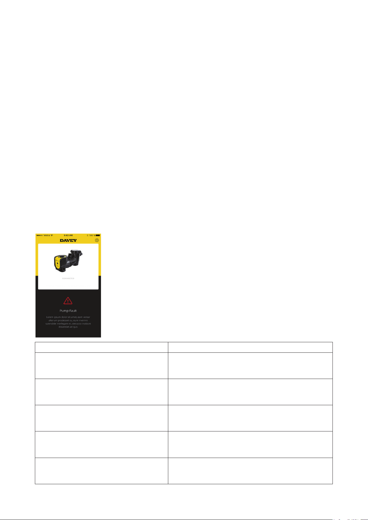
Pump fault finding
In the instance that there is a fault, the following screen will appear, with text description below the fault
indicating how to remedy.
SilensorPro BT
Fault title Fault description
Check that the motor can rotate freely. Unplug for 1
Pump fault – overcurrent
Pump fault – under voltage
minute and plug back in to reset. If problem persists call
Davey, or an authorised repair agent.
Supply voltage issue. When power is back to normal,
unplug for 1 minute and plug back in to reset.
Pump fault – over temperature
Pump fault – motor stalled
Pump fault – underload/loss of prime
Pump is too hot. Check the ambient temperature. Set to
lowest speed possible if ambient temperature is too high.
Check that the motor can rotate freely. Unplug for 1
minute and plug back in to reset.
Check if there’s enough water inside the pump. Unplug for
1 minute and plug back in to reset. If problem persists call
Davey, or an authorised repair agent.
English
13
Page 14

Pump fault – motor over temperature; or
Pump fault – over voltage; or
Pump fault – earth fault; or
Pump fault – system fault; or
Pump fault – output phase fault; or
Pump fault – power overload; or
Pump fault – EEPROM checksum; or
Pump fault – watchdog error; or
Pump fault – back EFM protection; or
Pump fault – thermistor fault; or
Pump fault – safe torque off; or
Pump fault – internal bus communication; or
Pump fault – application error; or
Pump fault – IGBT temperature high; or
Pump fault – 4mA analogue input fault; or
Pump fault – external fault; or
Pump fault – keypad communication error; or
Unplug for 1 minute and plug back in to reset. If problem
persists call Davey, or an authorised repair agent.
Pump fault – fieldbus communication error; or
Pump fault – fieldbus interface error.
7. ADVANCED SETUP OF SP400BT
External AUX connections overview
Your SilensorPRO SP400BT has an RJ45 style waterproof socket to allow for external control of motor speed
and other functionality. A standard RJ45 network cable (without boot) can be used.
Figure 1: RJ45 Plug installed in housing (from rear)
It is recommended to keep the cable length between the pump and external pool controller or heater as short
as possible. There are two major pin configurations as shown below:
RJ45 PINOUT
Figure 2: RJ45 pin connections
English
14
Page 15
Pin Function T-568A T-568B
1 RS485 +ve Green/white Orange/white
2 RS485 -ve Green Orange
3 Digital input 3 Orange/white Green/white
4 Analogue input Blue Blue
5 0V DC ground Blue/white Blue/White
6 Digital input 2 Orange Green
7 Digital input 1 Brown/white Brown/white
8 24V Brown Brown
Check that the cable you use has the above colour coding pins 1 through to 8. If an alternative colour coding
has been used make sure to record the colour which corresponds to each pin to avoid misconnection at
the pool controller or heater. If an alternative cable is used make sure the analogue input and ground are a
twisted pair.
The 24V connection is only to be used as a reference for the digital inputs – DO NOT power external
equipment from this supply rail.
Digital control inputs
The 3 digital inputs allow for overriding the dial speed setting. To set one of these inputs either:
• Connect an isolated 24V supply between DC ground and the digital input pin
• Connect the switched contacts of a relay between the 24V pin and the digital input
The fixed speeds (as a proportion of full speed) are:
Input 1 (Pin 7) Input 2 (Pin 6) Input 3 (Pin 3) Output Speed
0 0 0 Dial
0 0 24V 33%
0 24V 0 50%
0 24V 24V Backwash
24V 0 0 100%
24V 0 24V 67%
24V 24V 0 83%
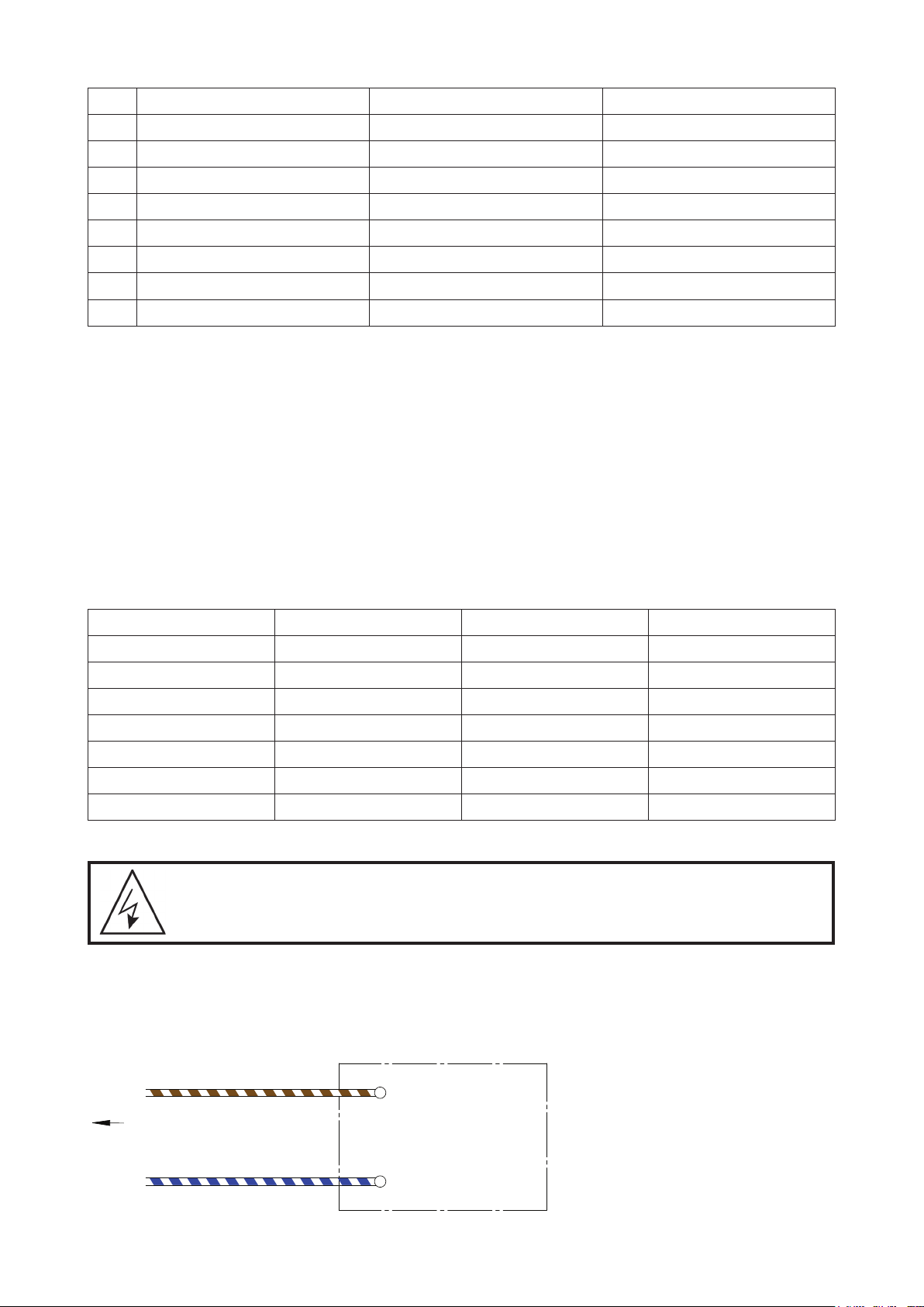
Interfacing equipment to the SilensorPRO SP400BT
WARNING! A qualied electrician is required to carry out the work shown below.
The SilensorPRO SP400BT can be controlled by other equipment to turn it on to high speed (or any other
pre-set speeds, see section 8 for details). This is to achieve maximum efficiency, for example, when using a
gas heater, or a heat pump. If the equipment has an isolated 18- 24V DC signal output, simply connect pin 7
to 24V DC positive and pin 5 to DC ground as shown in the following diagram:
Pin7 (Brown/White)
To RJ45 Socket of VSD Pump
Pin5 (Blue/White)
Controlling Equipment
+ 18 ~ 24V DC
DC Ground
English
15
Page 16
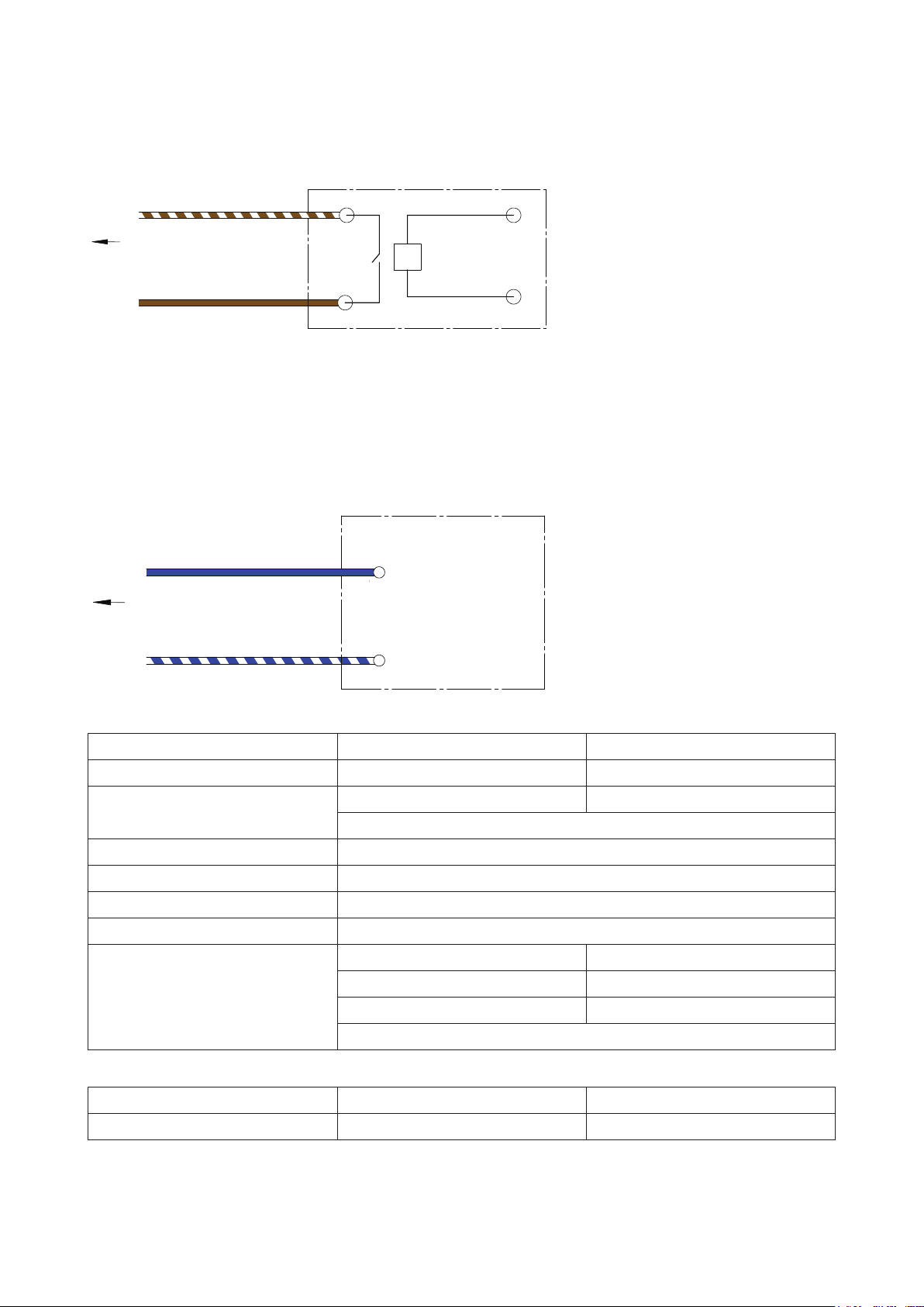
If the controlling equipment does not have 18-24V DC voltage output as above, but has 24V AC, 230V AC,
12V AC, or 12V DC etc. signal output, a suitable relay (the coil voltage must be the same as the signal output
voltage of the controlling equipment) can be used to do this job as mentioned above, and shown in the
following diagram:
Controlling Equipment
Pin7 (Brown/White)
To RJ45 Socket of VSD Pump
Pin8 (Brown)
Relay (Dry)
Contact
Relay Coil, must be
the same voltage
as the equipment
signal output
If the controlling equipment already has the relay output (dry contact) for controlling purpose, an extra relay
is not necessary, simply connect Pin 7 (Brown/White) and Pin 8 (Brown) to the dry contacts as shown in the
left part of the diagram above.
Analogue control inputs
Speed control can also be achieved by connecting a 0-10V DC signal at the input on pin 4 (ground at pin 5).
As soon as a signal above 0V is registered, this input will take priority over dial settings. For example, 10V
DC will change pump speed pump to 100%, 5V DC will change pump speed to 50% etc.
Controlling Equipment
+ 0~ 10 V DC Signal Output
Pin4 (Blue)
To RJ45 Socket of VSD Pump
Pin5 (Blue/White)
of controlling equipment
DC Ground
8. TECHNICAL SPECIFICATIONS
Model
Max head (m)
RPM
Enclosure class (IP)
Insulation class
Voltage (V)
Supply freq (Hz)
Motor input power: (W)
Operating Limits
Max water temperature:
Max ambient temperature:
Speed 1 – 10: 1,500 – 3,600 Speed 1 – 10: 1,050 – 3,100
Speed 10: 1,111 Speed 10: 1,639
SP200BT SP400BT
20 26
Backwash speed: variable
45
F
220 – 240VAC
50/60 Hz
Speed 1: 128 Speed 1: 126
Speed 5: 524 Speed 5: 728
Backwash speed: variable
40°C 40°C
50°C 50°C
16
English
Page 17
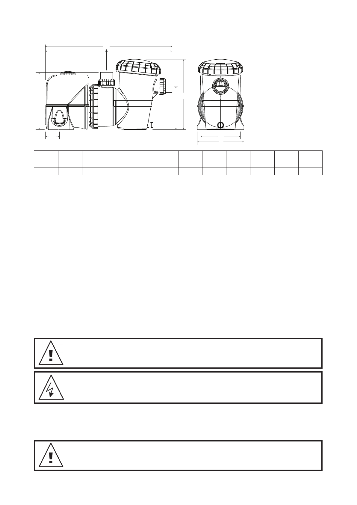
Dimensions
A
C
B
D
G
F
E
A
305mm 670mm 320mm 350mm 65mm 230mm 380mm 200mm 250mm 10mm 50/63 14
B C
D E F G H I
H
I
Mounting
Holes
Diameter
Inlet/Outlet
PVC
Net
Weight
(kg)
9. USING YOUR SILENSORPRO WITH A SALT WATER CHLORINATOR
Chlorinators require a minimum flow rate through the chlorinator cell for best efficiency and cell life. Please
refer to your chlorinator guide as a reference for the flow required by your pool system. Ensure flow rate is
enough to cover your chlorinator cell plates completely at all times of operation.
10. OPERATING YOUR SUCTION POOL CLEANER
Before installing or purchasing a pool cleaner for use with your SilensorPRO, it is important to know the
minimum flow rates required for it to operate effectively.
To operate a suction pool cleaner:
• Activate the High Flow setting (10) and allow the pump to fully prime by running for around 2 minutes. You
will know the pump is primed when you can see a strong flow of water through the clear leaf basket lid.
• When all air is expelled from the leaf basket, connect the pool cleaner hose firmly into the skimmer plate or
dedicated wall suction.
• Select the speed setting that enables best performance from your suction pool cleaner. Speed 3 to 7 should
be ample for most cleaners, however if the cleaner requires better performance, select speeds 7 to 10.
• The cleaner should only be connected for as long as is required to clean the surface of your pool. When
cleaning is complete, disconnect the cleaner and remove the skimmer plate from the skimmer box.
• Reactivate the most efficient speed setting for daily filtration. Speeds 1 to 4 is recommended.
NOTE: To get optimum energy efciency from your SilensorPRO, DO NOT keep the
suction pool cleaner connected when cleaning is not required.
NOTE: If the SilensorPRO is hard-wired into a time clock, or another automatic control,
the wiring should be removed by a qualied technician.
• Close the water valves on the pool return and the SilensorPRO inlet pipework;
• Remove the discharge & suction barrel unions taking care not to lose the o-rings;
• Move the pipework with the barrel unions attached until the SilensorPRO can be pulled clear.
NOTE: When making any enquiries about your SilensorPRO be certain to quote the
model number from the nameplate located on the motor.
English
17
Page 18

11. TROUBLE SHOOTING
If the pump runs but there is no water flow, or water flow is reduced, the following conditions may apply:
• The filter requires backwashing or it is blocked. Refer to the relevant section in the Filter Manual;
• The pump is not primed. Re-prime as per instruction in ‘Starting the pump’;
• There are air leaks in the suction piping. Check all piping and eliminate leaks, also check for a loose
strainer basket lid. Air bubbles in the water flowing back to the pool would indicate a leak in the suction to
the pump allowing air to enter the pipework.
• A leaking pump shaft seal may also prevent operation. Evidence of this would be water on the ground
under the pump.
• The pump is not able to get water from the pool. Check that the valves to the pump are fully open and
that the pool water level is up to the skimmer box. Typically, half way up the face of the skimmer box is
sufficient;
• Blockage in the piping or pump. Remove the strainer basket and check for any blockage to the pump
impeller entry. Check the skimmer box for blockage.
If the pump does not operate, the following conditions may apply:
• The power is not connected. For 220-240 volt only, check the power point by plugging in a portable
appliance to ensure power is available. Also check fuses and the main power supply switch;
• Automatic overload is tripped. The pump has an in-built thermal overload which will reset automatically
after the motor has cooled following an overheating period. Determine the cause of the overload tripping
and rectify. Reset the pump by switching the power OFF for 30 seconds;
• Blockage is preventing the pump from rotating.
12. REMOVAL OF THE SILENSORPRO FROM PIPEWORK
Should it be necessary to remove the SilensorPRO, follow these instructions:
• Switch off the power and remove the plug from the power source;
• Unscrew the barrel union on the front and top of the pump, releasing the pump from the pipework;
• Slide the pump out of position.
13. WATER QUALITY
RECOMMENDED POOL WATER CHEMISTRY
POOL WATER
BALANCING
Ideal Reading / Range 1 – 3
To Increase
Free Chlorine
(ppm)
Increase output of
chlorinator. Add
chlorine. Increase
ltration time.
pH
Concrete &
Tiled Pools:
7.4-7.6
Other Surfaces:
7.2-7.4
Add buffer
or soda ash
(Sodium
Carbonate)
Total Alkalinity TA
(ppm)
Concrete & Tiled
Pools – 80-120.
Other Surfaces –
125-150
Add Sodium
Bicarbonate
Calcium Hardness
(ppm)
Concrete & Tiled
Pools – 200-275.
Other Surfaces –
100-225
Add Calcium
Chloride
Stabiliser –
Cyanuric Acid
(ppm)
25 – 50 4500 – 6000
Add Cyanuric
Acid
Optimum
Salt Level
(ppm)
Add Salt
To Decrease
Frequency of Testing Weekly Weekly Weekly Weekly Regularly Regularly
Add Muriatic
Acid
Add Muriatic Acid
or Dry Acid
Partially drain &
rell pool with lower
hardness water to
dillute
Partially drain
& rell pool to
dillute
Partially drain
& rell pool
to dillute
English
18
Page 19
Routine Maintenance tasks - to maximise the life of your pool equipment & personal
safety, use this checklist once a week. Turn pump off rst.
a. Make sure that any pressure gauges are in working condition and the operating
pressure is within limits as specied on the product.
b. Make sure that each suction inlet and main drain has a cover that is securely
attached and in safe working condition.
c. Make sure that all skimmer covers are securely attached and in safe working
condition. These should be replaced every 3 to 4 years.
d. Remove any obstructions or debris from the main drain cover.
e. Ensure the skimmer baskets and the pump hair and lint pots are free of leaves and
debris at least once a week.
f. Remove obstructions and combustibles from around the pump motor.
g. Make sure all wiring connections are clean and that all wiring and electrical
equipment is in good condition. Damaged wiring must be repaired or replaced by a
qualied electrician as soon as damage is discovered.
h. Check water balance and sanitiser levels at your local pool shop.
POWER CONNECTIONS AND WIRING MUST BE CARRIED OUT BY AN AUTHORISED
ELECTRICIAN.
DANGER Hazardous suction. Do not block water entry into ltration system with any
part of your body as the pressure can trap hair or body parts, causing severe injury or
death. Do not block suction.
Turn off pump immediately if someone becomes trapped.
Do not use or operate swimming pools, spas or spa baths if a suction cover is broken,
missing or loose. Two suction covers and inlets must be provided into every pump to
avoid suction entrapment.
In accordance with AS/NZS60335.2.41 we are obliged to inform you that this device is
not to be used by children or inrm persons and must not be used as a toy by children.
CAUTION! Do not add chemicals directly to the pool skimmer. Adding undiluted
chemicals may damage pump and lter and void warranty.
19
English
Page 20

Davey warranty
Davey Water Products come with guarantees that cannot be excluded under the local country Law. You are
entitled to a replacement, or refund for a major failure and compensation for any other reasonably foreseeable
loss, or damage. You are also entitled to have the goods repaired or replaced if the goods fail to be of acceptable
quality and the failure does not amount to a major failure.
Davey Water Products Pty Ltd (Davey) of 6 Lakeview Drive Scoresby VIC 3179 provides the following warranty in
relation this product. Davey warrants that, subject to the exclusions and limitations below, the product will be free
from defects in material and workmanship for a period of 24 months from the date of purchase (warranty period).
If a defect appears in the product before the end of the warranty period and Davey finds the product to be
defective in materials or workmanship, Davey will, in its sole discretion, either:
1. replace or repair the product or the defective part of the product free of charge; or
2. arrange for the product or the defective part of the product to be repaired or replaced by a qualified repairer
free of charge.
Davey reserves the right to replace defective parts of the product with parts or components of similar quality,
grade and composition where an identical part or component is not available. Goods presented for repair may
be replaced by refurbished goods of the same type rather than being repaired.
Warranty claims:
1. If a fault covered by the warranty occurs, Davey suggests, in the first instance, that you contact the Davey
Dealer from whom you purchased the product. Alternatively, you can: phone the Davey Customer Service line
on 1300 367 866 in Australia, or 0800 654 333 in New Zealand; send a written letter to Davey at the address
listed above; or email sales@davey.com.au.
2. Any warranty claim must be accompanied by proof of purchase and details of the alleged defect.
3. On receipt of your claim, Davey will seek to resolve your difficulties, or if the product is faulty or defective,
advise you on how to have your product repaired, obtain a replacement or a refund.
4. This warranty is limited to defects in the materials or workmanship in the product and does not cover
expendable parts or the replacement of parts due to fair wear and tear.
Exclusions:
The warranty will not apply where:
1.
The Product has been modified, repaired or serviced by someone other than Davey, or an authorised repairer.
2. Davey cannot establish any fault in the product after testing.
3. The product has been used other than for the purpose for which it was designed.
4. The product has been subject to abnormal conditions, whether of temperature, water, humidity, pressure,
stress or similar.
5. The purchaser has used or fitted non-genuine, or non-approved parts and accessories.
6. The Product defect has arisen due to abuse, misuse, neglect or accident.
7. The Product defect has arisen due to the purchaser’s failure to properly maintain or use the product.
8. The damage has been caused by the use of chemicals and detergents not approved by Davey.
Should your Davey product require repair or service after the warranty period, please contact your nearest Davey
Dealer, or phone or email the Davey Customer Service Centre. For a complete list of Davey Dealers please visit
our website.
INTERNATIONAL
Australian Head Offi ce
Ph: +613 9730 9124
Fax: +613 9753 4248
Email: export@davey.com.au
Davey Water Products Pty Ltd
Member of the GUD Group
ABN 18 066 327 517
AUSTRALIA
Head Offi ce
6 Lakeview Drive,
Scoresby, Australia 3179
Ph: 1300 232 839
Fax: 1300 369 119
Email: sales@davey.com.au
Website: davey.com.au
® Davey is a trademark of Davey Water Products Pty Ltd. © Davey Water Products Pty Ltd 2019.
Website: davey.com.au
EUROPE
ZAC des Gaulnes
355 Avenue Henri Schneider
69330 Meyzieu, France
Ph: +33 (0) 4 72 13 95 07
Fax: +33 (0) 4 72 33 64 57
Email: info@daveyeurope.eu
Website: daveyeurope.eu
NEW ZEALAND
7 Rockridge Avenue,
Penrose, Auckland 1061
Ph: 0800 654 333
Fax: 0800 654 334
Email: sales@dwp.co.nz
Website: daveynz.co.nz
NORTH AMERICA
Ph: +1 866 328 7867
Email: export@davey.com.au
Website: daveyusa.com
MIDDLE EAST
Ph: +971 50 6368764
Fax: +971 6 5730472
Email: info@daveyuae.com
Website: daveyuae.com
20
P/N 403308-1
Page 21

SilensorPRO SP200BT und SP400BT
Schwimmbadpumpe
Installations- und Betriebs-anleitung
50/60 Hz
SP200BT
Für Aktualisierungen der Produktinformationen konsultieren Sie bitte die DaveyWebsite Ihrer Region, wie auf der Rückseite dieses Dokuments angegeben.
Bitte geben Sie diese Anweisungen an den Bediener dieser Anlage weiter.
SP400BT
Deutsch
Page 22

Wir beglückwünschen Sie zum Kauf einer hochwertigen SilensorPRO SP200BT bzw. SP400BT Pumpe. Alle
Komponenten wurden so konzipiert und hergestellt, dass sie einen störungsfreien und zuverlässigen Betrieb
gewährleisten.
Inhaltsverzeichnis:
1. INSTALLATION DER DREHZAHLGEREGELTEN PUMPE VON DAVEY ................................................23
Netzanschluss ..........................................................................................................................................23
Rohrleitungsanschluss ..............................................................................................................................24
2. TYPISCHER INSTALLATIONSPLAN .......................................................................................................25
3. LEISTUNGSDATEN ..................................................................................................................................25
3.1 SP200BT Hydraulische Leistung ........................................................................................................25
3.2 SP200BT Elektrische Spezifikationen .................................................................................................26
3.3 SP400BT Hydraulische Leistung ........................................................................................................26
3.4 SP400BT Elektrische Spezifikationen .................................................................................................26
4. BEDIENUNGSANLEITUNG......................................................................................................................27
Mit dem SilensorPRO Energie sparen ......................................................................................................27
Checkliste vor Inbetriebnahme .................................................................................................................27
Niedrigenergiebetrieb ...............................................................................................................................28
Richtlinien für empfohlene Pumpenbetriebszeiten ...................................................................................28
Siebkorb entleeren ....................................................................................................................................29
Routinewartung .........................................................................................................................................29
5. EIGENSCHAFTEN UND FUNKTIONEN ..................................................................................................30
Mehrfarbige LED-Anzeigeleuchte .............................................................................................................30
Rückspül-Speed-Cycling-Technologie ......................................................................................................30
Vollvariabler drehzahlgesteuerter Motor mit benutzerfreundlichem Drehzahlwähler ................................30
Großer 4,5l-Flusentopf ..............................................................................................................................30
Patentiertes wassergekühltes Design für reibungslosen und superleisen Betrieb ...................................30
SP400BT Konstante Durchfluss-/Drehzahlkompensation ........................................................................30
SP400BT wetterfester RJ45 Kommunikationsanschluss (s. Abschnitt 7 für Details) ................................30
6. BLUETOOTH-FUNKTIONALITÄT ............................................................................................................31
Einrichtung der Bluetooth-App ..................................................................................................................31
Gerät mit der Pumpe verbinden ................................................................................................................31
Externer Zeitnehmer / Chlorinator ............................................................................................................31
Zeitplan-Modus .........................................................................................................................................31
Zeitplan festlegen .....................................................................................................................................32
Einstellungen ............................................................................................................................................32
Ansaugdrehzahl/max. Drehzahl ................................................................................................................32
Rückspülung .............................................................................................................................................33
Externer Timer vorhanden ........................................................................................................................33
Funktion Trennen ......................................................................................................................................33
Auf Werkseinstellung zurücksetzen ..........................................................................................................33
Pumpen-Fehlersuche ...............................................................................................................................33
7. ERWEITERTE EINSTELLUNGEN VON SP400BT ..................................................................................34
Übersicht externe AUX-Anschlüsse ..........................................................................................................34
Digitale Steuerungseingänge ....................................................................................................................35
Schnittstellenequipment für die SilensorPro SP400BT .............................................................................35
Analoger Steuereingang ...........................................................................................................................36
8. TECHNISCHE DATEN ..............................................................................................................................36
9. VERWENDUNG DER SILENSOPRO MIT EINEM SALZWASSER-CHLORINATOR...............................37
10. BETRIEB EINES BECKEN-SAUGREINIGERS ........................................................................................37
11. FEHLERSUCHE .......................................................................................................................................38
12. SILENSORPRO VON ROHRLEITUNG ENTFERNEN .............................................................................38
13. WASSERQUALITÄT .................................................................................................................................38
14. DAVEY-GARANTIE ...................................................................................................................................40
22
Deutsch
Page 23
1. INSTALLATION DER DREHZAHLGEREGELTEN PUMPE VON DAVEY
SilensorPRO sollte so nah wie möglich am Wasser stehen und auf einem festen Untergrund in einer gut
entwässerten Position montiert werden, die hoch genug ist, um Überschwemmungen zu vermeiden. Es liegt in der
Verantwortung des Monteurs/Besitzers, die Pumpe so aufzustellen, dass das Typenschild einfach abzulesen ist und
SilensorPRO für Wartungen jederzeit zugänglich ist. Es wird empfohlen, SilensorPRO vor Witterungseinflüssen zu
schützen. Umbauten sollten gelüftet sein, um die Bildung von Kondensation zu vermeiden.
Die Nichtbeachtung dieser Anweisungen und die Nichteinhaltung aller geltenden
Vorschriften können zu schweren Körperverletzungen und/oder Sachschäden führen.
Für die Installation und Wartung dieser Pumpe ist professionelles Fachwissen
erforderlich. Die Installation dieses Produkts sollte von einer Person durchgeführt
werden, die mit den Anforderungen von Poolinstallationen vertraut ist und welche die
Installationsanweisungen in diesem Handbuch befolgt.
Netzanschlüsse
WICHTIGER HINWEIS Ihr SilensorPRO ist gegen den Wasserkreislauf doppelt isoliert.
Wenn eine Potentialausgleichsvorrichtung erforderlich ist, wird ein PotentialausgleichsPunkt mitgeliefert. (Bitte beachten Sie die örtlichen Standards und Vorschriften zur
Verdrahtung, wie beispielsweise AS/NZ 3000).
VORSICHT! Im Interesse Ihrer eigenen Sicherheit empfehlen wir, dass alle
Marken und Typen von Poolpumpen gemäß AS/NZS 3000, den nationalen
Anschlussreglementierungen, oder gleichwertigen lokalen Reglementierungen
installiert werden. Alle elektrischen Installationen müssen von einem qualizierten
Elektriker ausgeführt werden. Davey empehlt, alle Anlagen mit einem Erdschluss
oder Fehlerstrom-Schutzeinrichtungen auszustatten. Nennfehlerbetriebsstrom von
höchstens 30mA.
WARNUNG! Stellen Sie sicher, dass es einen einfach zugänglichen Trennschalter gibt,
mit dem sich die Pumpe im Notfall ausschalten lässt.
F NFC C 15-100 GB BS7671:1992
D DIN VDE 0100-702 EW EVHS-HD 384-7-702
A OVE 8001-4-702 H MSZ 2364-702:1994/MSZ 10-533 1/1990
E UNE 20460-7-702 1993, REBT ITC-BT-31 2002 M MSA HD 384-7-702.S2
IRL IS HD 384-7-702 PL PN-IEC 60364-7-702: 1999
I CEI 64-8/7 CZ CSN 33 2000 7-702
LUX 384-7.702 S2 SK STN 33 2000-7-702
NL NEN 1010-7.702 SLO SIST HD 384-7-702.S2
SilensorPRO ist für den Anschluss an eine Versorgungs-Nennspannung von 220 – 240 Volt 50/60Hz
vorgesehen und mit einem flexiblen Anschlusskabel ausgestattet. Wenn für die Pumpe in einem Umkreis
von 3 Metern kein Spannungsanschluss verfügbar ist, muss der Elektriker an einem sicheren, trockenen
Ort einen 3-poligen Stromanschluss installieren. Verlängerungskabel im Poolbereich sind eine Gefahr und
sollten vermieden werden. Wenn das Netzkabel der SilensorPRO beschädigt ist, muss es von Davey oder
einem autorisierten Händler durch ein echtes Davey-Ersatzteil ausgetauscht werden.
SilensorPRO verfügt über einen Motorüberlastschutz, der den Motor vor Überhitzung schützt. Wenn
der Motor während des Betriebs zu heiß wird, wird die Drehzahl reduziert, um ihn auf eine akzeptable
Betriebstemperatur abzukühlen und ihn dann auf die eingestellte Drehzahl beschleunigen.
Um den Motor zurückzusetzen, schalten Sie das Gerät für 30 Sekunden aus und schalten Sie dann den
Netzschalter wieder ein.
Deutsch
23
Page 24
Rohrleitungsanschluss
Figure 1.2
152mm
MINIMUM
76mm
MINIMUM
Suction line
50/63mm
Return to
Pool
50/63mm
Return to
Für den Anschluss an die Rohrleitung aus dem Becken sind Fassverschraubungen vorgesehen. Die Pumpe
ist so ausgelegt, dass sie mit 50/63 mm PVC-Verschraubungen verbunden werden kann.
WICHTIGER HINWEIS Benden sich Pumpe und Filter unterhalb des
Beckenwasserspiegels, müssen Absperrventile in der Rohrleitung zwischen Pumpe und
Skimmer und in der Rücklaueitung vom Filter zum Becken eingebaut werden. Bei der
Verbindung der Auslassleitung ist darauf zu achten, dass die Verbindung nicht in die
Drehzahlanzeige der Pumpe eingreift. Fassverbindungen müssen per Hand angezogen
werden. Dichtungsmittel, Kleber oder Silikone werden nicht benötigt.
Die Verschraubungen an SilensorPRO bestehen aus ABS. Manche PVC-Dichtungsmassen
sind nicht mit ABS verträglich. Prüfen Sie die Eignung der Dichtmasse vor der Verwendung.
Die Verwendung von Rohren mit geringerem Durchmesser als angegeben wird nicht empfohlen. Die
Ansaugverbindungen sollten frei von Luftlecks, Höckern und Hohlräumen sein, die Probleme beim Ansaugen
verursachen. Für einen optimalen Wirkungsgrad sollte der SilensorPRO so installiert werden, dass
Wasserwirbel so weit wie möglich begrenzt werden. Wie in Abbildung 1.1 dargestellt, keinen 90°-Ellbogen
näher als 250 mm an der Rohrverschraubung am Einlass installieren. Absperrventile unterhalb des
Beckenwasserspiegels sollten ebenfalls nicht näher als 250 mm vor der Rohrverschraubung am Einlass
installiert werden. Diese Maßnahme unterstützt laminare Strömung.
Figure 1.1
250mm
ELBOW
Suction line
50/63mm
Pool
50/63mm
Die Auslassleitung von SilensorPRO sollte an den Eingangsanschluss des Beckenfilters (in der Regel am
Filterregelventil) angeschlossen werden. Wie in Abbildung 1.2 dargestellt, auf ausreichenden Platz über
der Pumpe achten, um die Kurzwahltasten von SilensorPRO nicht zu beeinträchtigen. Verwenden Sie ein
Rückschlagventil in der Druckleitung, wenn Sie diese Pumpe für alle Anwendungen verwenden, bei denen
die Höhe der Rohrleitung nach der Pumpe groß ist.
Figure 1.2
Return to
Pool
50/63mm
152mm
MINIMUM
Suction line
50/63mm
Stellen Sie sicher, Rückschlagventile zu installieren, wenn Sie die Pumpe mit einer anderen Pumpe
betreiben. Dies schützt vor einer umgekehrten Rotation des Impellers und des Motors.
76mm
MINIMUM
WARNUNG! Der Saugdruck der Pumpe ist gefährlich und kann Badegäste erfassen und
ertränken, oder ausweiden. Den Absaugstutzen nicht blockieren. Betreiben Sie keine
Schwimmbäder, Spas oder Spa-Bäder, wenn eine Saugabdeckung gebrochen ist, fehlt
oder lose ist. In jede Pumpe müssen zwei Saugabdeckungen oder -Einlässe eingebaut
werden, um ein Einklemmen des Saugers zu vermeiden.
24
Deutsch
Page 25

2. TYPISCHER INSTALLATIONSPLAN
ProMaster - PM200SV
Performance
Pool pump Media Filter
3. LEISTUNGSDATEN
3.1 SP200BT Hydraulische Leistung
25
20
15
Total Head ( m )
10
5
Dial position No. 10
Dial position No. 9
Dial position No. 8
Dial position No. 7
Dial position No. 6
Dial position No. 5
Dial position No. 4
Dial position No. 3
Dial position No. 2
Dial position No. 1
0
0 50 100 150 200 250 300 350 400
Flow ( lpm )
0
036 9 12 15 18 21 24
3
Flow ( m
25
/h )
Deutsch
Page 26
3.2 SP200BT Elektrische Spezifikationen
450
Drehzahl
Einstellung
Einstellung 1 0,17 128 0,12 90
Einstellung 2 0,28 207 0,19 145
Einstellung 3 0,39 293 0,27 205
Einstellung 4 0,53 398 0,37 279
Einstellung 5 0,70 524 0,49 367
Einstellung 6 0,87 655 0,61 459
Einstellung 7 1,08 807 0,75 565
Einstellung 8 1,25 936 0,87 655
Einstellung 9 1,44 1078 1,01 755
Einstellung 10 1,48 1111 1,04 778
PS W PS W
Eingang Ausgangs
3.3 SP400BT Hydraulische Leistung
25
Dial position No. 10
Dial position No. 9
Dial position No. 8
20
15
Dial position No. 7
Dial position No. 6
Dial position No. 5
Dial position No. 4
Dial position No. 3
Dial position No. 2
Dial position No. 1
Total Head ( m )
10
5
0
0 50 100 150 200 250 300 350 400
Flow ( lpm )
0
036 9 12 15 18 21 24 27
3
Flow ( m
/h )
3.4 SP400BT Elektrische Spezifikationen
Drehzahl
Einstellung
Einstellung 1 0,17 126 0,12 89
Einstellung 2 0,28 210 0,20 147
Einstellung 3 0,46 347 0,32 243
Einstellung 4 0,70 522 0,49 366
Einstellung 5 0,97 728 0,68 510
Einstellung 6 1,22 913 0,85 639
Einstellung 7 1,61 1211 1,13 848
Einstellung 8 1,97 1478 1,38 1034
Einstellung 9 2,18 1635 1,59 1191
Einstellung 10 2,19 1639 1,62 1212
PS W PS W
Eingang Ausgangs
26
Deutsch
Page 27

4. BEDIENUNGSANLEITUNG
Die Pumpe verfügt über einen Bluetooth-Anschluss, sodass Sie die Pumpe mit ihrem Smart-Gerät einrichten
und kontrollieren können. Bluetooth ist ein kabelloses Kommunikationsprotokoll, das die Kommunikation
zwischen Geräten ermöglicht. Diese Funktion wird von allen Geräten unterstützt, die Anwendungen für iOS
oder aus dem Android App Store herunterladen können.
Lesen Sie diese Anweisungen komplett, bevor Sie die Pumpe einschalten. Sollten Sie Teile dieser
Installations- und Bedienungsanweisungen nicht verstanden haben, kontaktieren Sie bitte Davey (siehe Liste
am Ende dieses Dokuments).
Jede SilensorPRO wird gründlich gegen eine Reihe von Durchfluss-, Druck-, Spannungs-, Strom- und
mechanischen Leistungsparametern getestet. Die fortschrittliche Pumpenfertigungstechnik von Davey
ermöglicht eine langanhaltende verlässliche und effiziente Pumpenleistung.
Mit dem SilensorPRO Energie sparen
Die drehzahlgesteuerte Pumpe von Davey ist eine hocheffiziente Pumpe mit einem regelbaren
Wechselstrommotor mit einem niedrigen Schallpegel, niedrigeren Betriebskosten und niedrigeren TreibhausEmissionen als traditionelle Poolpumpen.
Aufgrund ihrer Fähigkeit, mit niedrigeren Drehzahlen als herkömmliche Pumpen zu arbeiten, ist der
mechanische Verschleiß niedriger aufgrund einer geringeren Belastung der mechanischen Komponenten.
Energie-effizientes Pumpen ist einfach zu erreichen. Lassen Sie die Filtrationspumpe auf einer niedrigeren
Drehzahl, aber dafür länger laufen als eine konventionelle Pumpe mit fester Drehzahl, um Ihr PoolWasser für eine angemessene Filtration und Säuberung auszutauschen. Das Ergebnis ist ein geringerer
Energieverbrauch und bis zu 70% niedrigere Betriebskosten.
SilensorPRO verfügt über einstellbare Drehzahleinstellungen, so dass Sie die Drehzahl, mit der Sie
Ihr Pool- oder Spa-Wasser zirkulieren, variieren können. Die Drehzahlen können eingestellt werden,
um einen Becken-Saugreiniger, ein Bodenreinigungssystem und Poolheizungen zu betreiben. Eine
Rückspüleinstellung kann an der Pumpe ausgewählt werden, um den einen Medienfilter zu spülen.
Was Sie von Ihrem SilensorPRO (energieeffizienter Betrieb) am Pool erwarten können:
• Wenn Ihre SilensorPRO-Pumpe eine herkömmliche Wechselstrom-Motorpumpe ersetzt, müssen Sie sie
eventuell länger laufen lassen als Ihre alte Pumpe mit fester Drehzahl. Das ist NORMAL und spart Energie
bei niedrigen Drehzahlen.
• Sie werden bemerken, dass die Druckanzeige an Ihrem Filter einen viel niedrigeren Druck als Sie gewohnt
sind anzeigt. Das ist ebenfalls NORMAL. Der niedrigere Systemdruck ist ein Ergebnis der niedrigeren
Drehzahl und Durchflussrate der Pumpe.
• Wenn die Pumpe bei niedrigeren Drehzahlen läuft, werden Sie eine signifikante Reduzieren des
Pumpen-Schallpegels bemerken. Dies ist ein großer Vorteil für Sie, da Sie SilensorPRO während der
Spitzenstromtarife betreiben können, was auch zur Senkung Ihrer Betriebskosten beiträgt. Außerdem
werden Ihre Nachbarn sehr viel zufriedener sein.
Viele Poolprodukte sind auf Mindestdurchflussmengen angewiesen, um einen optimalen Betrieb
und/oder Wirkungsgrad zu gewährleisten. Wenn Sie an SilensorPRO niedrige Durchflusswerte
verwenden (d.h. Drehzahl 1 bis 4), empfiehlt Davey, dass Sie die Kompatibilität der Drehzahl oder der
Mindestdurchflussmenge prüfen, die für den Betrieb bestimmter Poolausrüstungen erforderlich ist, wie z.B.:
• Becken-Saugreiniger; • Salzwasser-Chlorinatorzellen;
• Ozongeneratoren; • Bodenreinigungssysteme
• Solar-Heizsysteme;
Checkliste vor Inbetriebnahme
• Die gewählte Drehzahleinstellung ist eine kompatible Einstellung mit anderen Poolgeräten;
• Die Pumpe in einer sicheren und trockenen Umgebung installiert ist;
• Der Pumpenraum sollte für den Fall einer Undichtigkeit über ein geeignetes Abflusssystem verfügen;
• Eventuell vorhandene Transportstopfen sind zu entfernen;
• Die Rohrleitungen müssen sachgerecht abgedichtet und abgestützt sein;
• Die Pumpe wurde richtig angesaugt;
• Die Stromversorgung ordnungsgemäß angeschlossen ist;
• Alle Vorkehrungen für einen sicheren Betrieb getroffen wurden;
• Der Filter wurde mit einer 50/63 mm Rohrleitung versehen;
• Die (App)Betriebszeiteneinstellungen korrespondieren mit allen anderen Zeiten im System.
Deutsch
27
Page 28

Niedrigenergiebetrieb
Ihr SilensorPRO SP200BT verfügt über Drehzahleinstellungen von 1500 - 3600 U/min. Der SilensorPRO
SP400BT verfügt über Drehzahleinstellungen von 1050 - 3100 U/min. Die Drehzahl 1 ist die langsamste und
Drehzahl 10 die schnellste.
• Drehzahl 1 bietet die niedrigste Drehzahl und damit die größte Energieeffizienz und Einsparung.
Betrieb
Rückspülung des Medienfilters
Poolfiltration
Betrieb des Becken-Saugreinigers
Reinigen Ihres Pools
Wasserfeature-Betrieb
Spa-Jet-Betrieb
Bodenreinigungssysteme
Solar-Poolheizung
Empfohlene Drehzahleinstellung
Rückspülgeschwindigkeit
Drehzahl 1 bis 4
Drehzahl 5 bis 8
Drehzahl 9 bis 10
Richtlinien für empfohlene Pumpenbetriebszeiten
Die typische Umschlagshäufigkeit in Privatanlagen sollte ein einziger Umsatz des gesamten
Poolwasservolumens innerhalb des Zeitraums sein, in dem die Pumpe normalerweise in Betrieb ist. Die
folgende Tabelle gibt lediglich einen Überblick über die Laufzeiten Ihrer Pumpe im Filtrationsbetrieb, um die
Mindestumschlagsleistung zu erreichen:
SilensorPRO SP200BT
Poolgröße
(Liter)
Drehzahl 1 Drehzahl 5 Drehzahl 10
Drehzahleinstellung (Stunden)
20.000 3,3 1,7 1,1
30.000 5,0 2,5 1,7
40.000 6,7 3,3 2,2
50.000 8,3 4,2 2,8
60.000 10,0 5,0 3,3
80.000 13,3 6,7 4,4
100.000 16,7 8,3 5,6
SilensorPRO SP400BT
Poolgröße
(Liter)
20.000 2,4 1,3 0,9
30.000 3,7 2,0 1,4
40.000 4,9 2,7 1,9
50.000 6,1 3,3 2,3
60.000 7,4 4,0 2,8
80.000 9,8 5,3 3,8
100.000 12,3 6,7 4,7
Drehzahleinstellung (Stunden)
Drehzahl 1 Drehzahl 5 Drehzahl 10
28
Deutsch
Page 29

Nach EN60335.1 sind wir verpichtet, Sie darüber zu informieren, dass dieses Produkt
von Kindern ab 8 Jahren und Personen mit physischen, sensorischen oder geistigen
Einschränkungen oder mangelnder Erfahrung und mangelnden Kenntnissen verwendet
werden kann, sofern sie entsprechend beaufsichtigt oder in der sicheren Verwendung
dieser Anlage angeleitet wurden und mit den damit verbundenen Gefahren vertraut
gemacht wurden. Kinder müssen während der Nutzung beaufsichtigt werden, um
sicherzustellen, dass sie nicht mit dem Produkt spielen.
Siebkorb entleeren
Der Siebkorb sollte regelmäßig durch den Klarsichtdeckel inspiziert und entleert werden, wenn eine
Anhäufung von Abfällen erkennbar ist. Befolgen Sie die Anweisungen unten.
• Schalten Sie die Pumpe aus;
• Schrauben Sie den Siebkorbdeckel gegen den Uhrzeigersinn ab und nehmen Sie ihn ab;
• Entfernen Sie den Siebkorb, indem Sie ihn nach oben aus dem Gehäuse heben;
• Entleeren Sie den eingefangenen Müll aus dem Korb. Spülen Sie ihn bei Bedarf mit Wasser aus.
HINWEIS: Schlagen Sie den Plastikkorb NIEMALS auf eine harte Oberäche, da dies zu
Beschädigungen führen kann.
• Prüfen Sie den Siebkorb auf Risse, tauschen Sie den Siebkorb in der Pumpe ggf. aus;
• Setzen Sie den Deckel wieder auf und vergewissern Sie sich, dass er den großen O-Ring aus Gummi
abdichtet. Es ist nur eine handfeste Abdichtung erforderlich. Der O-Ring und das Gewinde können mit
Schmiermittel der Marke Hydra Slip oder gleichwertigen Produkten geschmiert werden.
Die Nichteinhaltung der regelmäßigen Wartung kann zu Schäden führen, die nicht unter
die Garantie fallen.
Routinewartung
Verwenden Sie diese Checkliste einmal pro Woche, um die Lebensdauer des SilensorPRO zu maximieren
und ihre persönliche Sicherheit zu gewährleisten. Vor dem Beginn sicherstellen, dass die Pumpe
ausgeschaltet ist:
• Stellen Sie sicher, dass sich alle Manometer im Betriebszustand befinden und der Betriebsdruck innerhalb
der auf dem Produkt angegebenen Grenzen liegt;
• Vergewissern Sie sich, dass jeder Ansaug- und Hauptablass mit einer Abdeckung versehen ist, die sicher
befestigt ist und sich in einem sicheren Betriebszustand befindet;
• Stellen Sie sicher, dass alle Abdeckungen des Skimmers sicher befestigt sind und sich in einem sicheren
Betriebszustand befinden. Diese sollten alle 3 bis 4 Jahre ausgetauscht werden;
• Entfernen Sie alle Hindernisse oder Fremdkörper von der Hauptablaufabdeckung;
• Stellen Sie sicher, dass die Skimmer- und Pumpenkörbe mindestens einmal pro Woche von Laub und
Schmutz befreit werden;
• Entfernen Sie Hindernisse und brennbare Stoffe rund um den Pumpenmotor;
• Vergewissern Sie sich, dass alle Kabelverbindungen sauber und alle Kabel und elektrischen Geräte in
gutem Zustand sind. Beschädigte Leitungen müssen von einem qualifizierten Elektriker repariert oder
ersetzt werden, sobald Schäden festgestellt werden;
• Überprüfen Sie den Wasserhaushalt und die Desinfektionsmittelstände in Ihrem örtlichen
Poolzubehörgeschäft.
Deutsch
29
Page 30

5. EIGENSCHAFTEN UND FUNKTIONEN
Der SilensorPRO verfügt über mehrere Betriebsfunktionen. Im Folgenden werden diese einzeln erklärt.
Mehrfarbige LED-Anzeigeleuchte
Wird verwendet, um die erforderlichen Einstellungen für die Programmierzeit für maximale Drehzahl (Boost-)
Zyklen und Warnungen zu identifizieren:
• Leuchtet Grün = Normaler Einstellungsbetrieb
• Blinkt langsam Grün = Rückspülung
• Blinkt schnell Grün = AUX Externe Steuerung
• Leuchtet Weiß = Zeit zum Rückspülen
• Blinkt schnell Weiß = Fehler - Pumpe zurücksetzen
• Blinkt langsam Blau = Steuerung durch Bluetooth
• Leuchtet Blau = Bluetooth-Modus
Rückspül-Speed-Cycling-Technologie
Im Rückspülmodus schaltet die SilensorPRO zwischen einer niedrigen und einer hohen Drehzahl um, um
das Filtermedium für eine effektivere Reinigung zu bewegen. Dies vermindert die Verschwendung von
Wasser und Chemikalien während des Rückspülvorganges.
Vollvariabler drehzahlgesteuerter Motor mit benutzerfreundlichem
Drehzahlwähler
• Ermöglicht eine einfache Auswahl der gewünschten Filtrationsgeschwindigkeit
• Keine komplizierten digitalen Druckknopfsteuerungen
Großer 4,5l-Flusentopf
• Ermöglicht längere Reinigungsintervalle
Patentiertes wassergekühltes Design für reibungslosen und superleisen
Betrieb
SilensorPRO hat eine wassergekühlte Membran und einen Mantel um den Motor herum, der die Pumpe
während des Betriebs kühl hält. Die Abwärme des Motors wird in das Schwimmbadwasser übertragen und
trägt so zur Senkung der Kosten für die Heizenergie des Schwimmbeckens bei.
SP400BT Konstante Durchfluss-/Drehzahlkompensation
Mit zunehmender Verschmutzung des Poolfilters, baut sich Druck auf. Bei einer typischen Poolpumpe
würde dies den Durchfluss durch das System allmählich verlangsamen. Der SilensorPRO erkennt den von
einem Filter angelegten Widerstand und kompensiert den verminderten Durchfluss automatisch durch eine
Erhöhung der Motordrehzahl. Das Ergebnis ist, dass der Durchfluss zwischen den Filterreinigungen konstant
bleibt.
Wenn der SilensorPRO erkennt, aufgrund der Drehzahlerhöhung die Zeit zum Rückspülen des Filters
gekommen ist, leuchtet die LED-Anzeige durchgehend weiß (siehe oben).
SP400BT wetterfester RJ45 Kommunikationsanschluss
(s. Abschnitt 7 für Details)
• Zur Kommunikation und Verbindung mit externen Pool-Kontrollsystemen
• Zum Empfang eines Signals von einer Wärmepumpe oder einem Gasheizgerät, um die SilensorPRODrehzahl während des Heizvorgangs auf volle Drehzahl zu erhöhen
• Service-Diagnose und Software-Updates (nur für Davey)
Deutsch
30
Page 31

6. BLUETOOTH-FUNKTIONALITÄT
Einrichtung der Bluetooth-App
• Öffnen Sie den „App-Store“, der auf Ihrem Gerät verfügbar ist.
• Suchen Sie „Davey Pool Pump“
• Installieren Sie die App auf Ihrem Gerät
Die App kann auf so vielen Geräten wie gewünscht installiert werden. Es kann jedoch nur ein Gerät
gleichzeitig die Pumpe steuern. Die Sprach- und Zeiteinstellungen der App sind dieselben wie auf Ihrem
Gerät. Die Maßeinheiten werden automatisch auf die Regioneneinstellung auf Ihrem Gerät eingestellt, Sie
können aber auch zwischen Litern, Gallonen oder m
Gerät mit der Pumpe verbinden
• Öffnen Sie die App auf Ihrem Smart-Gerät.
• Schalten Sie die Pumpe von „Aus“ auf „Bluetooth“, die LED blinkt eine Sekunde lang weiß.
• Drücken Sie den Knopf Verbinden auf Ihrem Gerät.
• Wählen Sie NUR beim ersten Einrichten „JA“, um den Standort zu erlauben.
• Bitte beachten Sie, dass wenn die Geräte zum ersten Mal gekoppelt werden, ein Zeitlimit von 2 Minuten
besteht um dies durchzuführen bevor die Prozedur wiederholt werden muss.
Externer Zeitnehmer / Chlorinator
Ein Pop-Up wird auftauchen und Sie fragen, ob Sie einen externen
Zeitnehmer oder Chlorinator zur Steuerung der SilensorPRO verwenden.
Bitte wählen Sie „ja“ oder „nein“. Dies ist eine Sicherheitsfunktion, die dazu
beiträgt, dass der Chlorinator nur dann läuft, wenn die Pumpe arbeitet.
3
/h auswählen.
Hinweis: Die App-Screenshots dienen nur zu Demonstrationszwecken. Die
tatsächlichen Bildschirme können anders aussehen.
Manueller oder Zeitplan-Modus
Zwei Modi sind verfügbar, je nachdem ob Sie SilensorPRO manuell
steuern oder alternativ einen Operationsplan aufstellen möchten.
Manueller Modus
• Drücken Sie „zu manuellem Modus wechseln“, falls im Planungsmodus
• Die App ist jetzt im manuellen Modus und Sie können die Drehzahl
manuell verstellen, durch Drücken der (+/-) Knöpfe.
• Im manuellen Modus läuft SilensorPRO in der eingestellten Drehzahl,
selbst wenn das Telefon nicht in der Nähe ist.
• Jedes Mal wenn der Schalter auf die Bluetooth-Position gestellt wird, wird
sie nach dem Ansaugzyklus mit der voreingestellten Drehzahl laufen.
Zeitplan-Modus
• Es gibt zwei Möglichkeiten (einen Tageszyklus oder einen Wochenzyklus
einstellen) durch Drücken des gewünschten Kästchens.
• Mit dieser Option können Sie entweder einen Standard „Tagesablauf“
erstellen, der die eingestellten Pegel jeden Tag konsistent bedient;
Dieses Pop-Up
tauch auf
SilensorPro BT
Um zwischen manuellem Modus oder Zeitplan-Modus zu wechseln, können Sie diesen
Knopf drücken.
31
Deutsch
Page 32
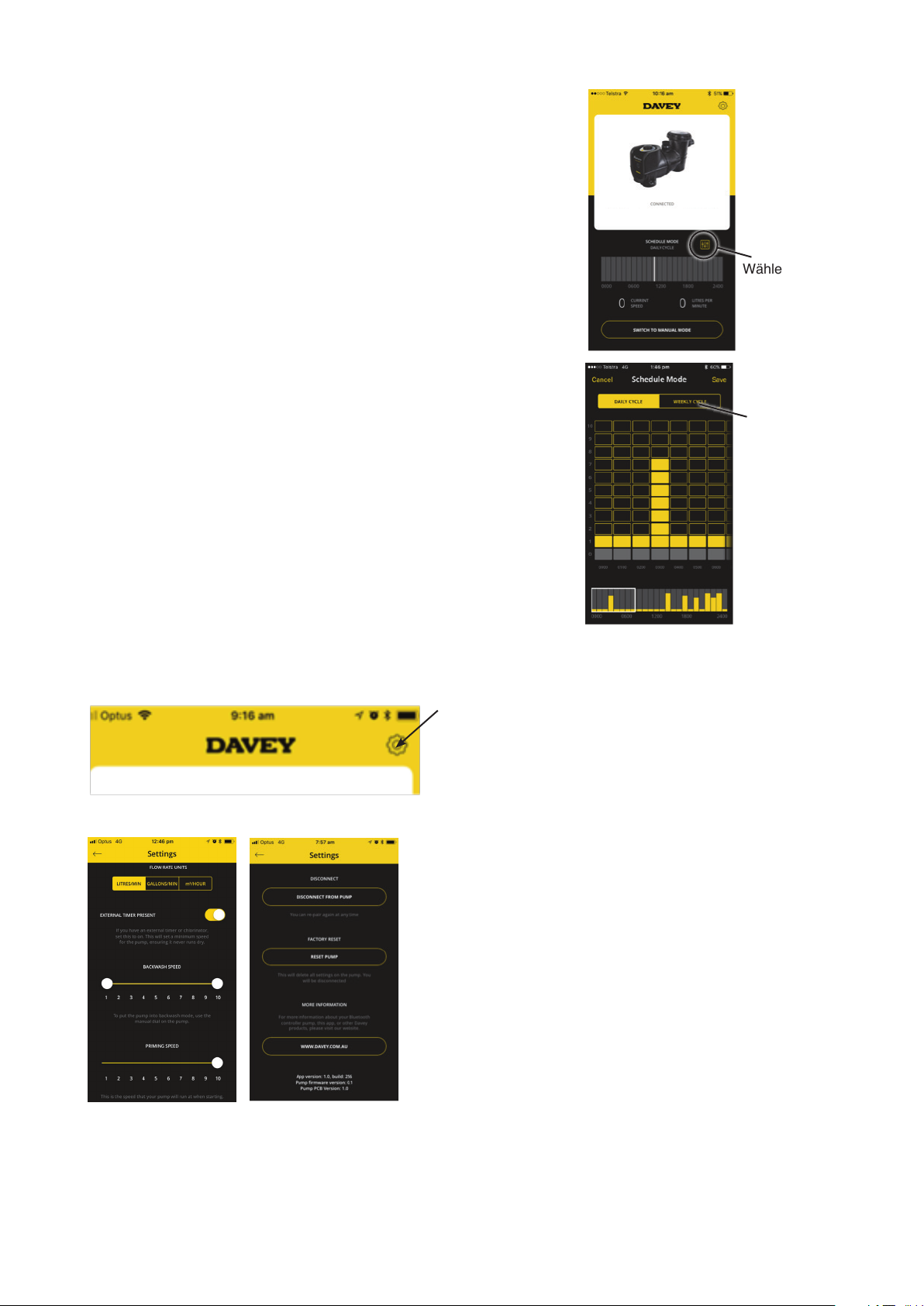
Es gibt zwei Möglichkeiten (einen Tageszyklus oder einen
Wochenzyklus einstellen) durch Drücken des gewünschten Kästchens.
Mit dieser Option können Sie entweder einen standardmäßigen
„Tagesablauf“ erstellen, der die eingestellten Pegel jeden Tag
konsistent bedient
• Die Option „Wochenzyklus“ kann für die gesamte Woche eingestellt
werden, was Ihnen die Möglichkeit gibt, die täglichen Pumpenzyklen
je nach Wetter, Badelast etc. zu ändern.
SilensorPro BT
Zeitplan festlegen
• Wählen Sie das Kästchen, das sich auf die Zeit bezieht, die Sie für
den Betrieb der Pumpe benötigen;
• Wählen Sie die Drehzahleinstellung, mit der die Pumpe jederzeit
laufen soll. Hinweis: Einstellungen der Pumpe (1-10) beziehen sich
auf die langsamste bis schnellste Betriebsdrehzahl der Pumpe);
• Wenn Sie mit Ihrem Zeitplan zufrieden sind, wählen Sie „Speichern“.
Die Kommunikation zwischen dem Gerät und der Pumpe kann je
nach gewähltem Zeitplan bis zu 20 Sekunden dauern;
• Die Zeile am unteren Rand des Bildschirms zeigt eine
Zusammenfassung, wo sich der Zeitplan nach Tag und Stunde
befindet. Dieser Übersichtsbildschirm kann leicht geändert werden,
indem man die obigen Spalten nach oben oder unten bewegt;
• Hinweis: Wenn Sie einen Chlorinator verwenden, müssen Sie
sichergehen, dass die „an“-Zeiten der Pumpe mit den „an“-Zeiten
des Chlorinators übereinstimmen. Die Pumpe bleibt im zuletzt
benutzten Modus, unabhängig davon, ob es sich um den manuellen
Modus oder den Zeitplanmodus handelt.
Einstellungen
Um Einstellungen zu ändern/einzustellen, klicken Sie auf das Einstellungensymbol:
Wählen Sie
diese Option,
um die Zeitplaneinstellungen
zu bearbeiten
Wählen Sie, ob
Sie den Tageszyklus oder den
Wochenzyklus
wünschen.
Es werden die folgenden Bildschirme angezeigt (scrollen Sie nach unten, um alle Informationen zu erhalten).
Ansaugdrehzahl/max. Drehzahl
Jedes Mal, wenn Ihre Pumpe startet, wird sie 2 Minuten lang angesaugt, um sicherzustellen, dass sich
Wasser im System befindet. Sie können die Drehzahl zwischen 5 und 10 einstellen. Die von Ihnen
eingestellte Drehzahl begrenzt die maximale Drehzahl, mit der die Pumpe im manuellen oder zeitgesteuerten
Betrieb betrieben wird.
Deutsch
32
Page 33

Rückspülung
Kann als einzelne Drehzahl oder alternativ als zwei Drehzahlen eingestellt werden und die Pumpendrehzahl
wird zwischen den beiden Einstellungen hin und her „pulsieren“. Die minimale Drehzahl kann zwischen 1
und 10 eingestellt werden, die maximale Drehzahl kann nur zwischen 5 und 10 eingestellt werden.
Externer Timer vorhanden
Diese Funktion kann ein- oder ausgeschaltet werden, je nachdem, ob Sie eine externe Zeitschaltuhr/
Chlorinator verwenden oder nicht.
Funktion Trennen
Die Funktion „Von der Pumpe Trennen“ kann verwendet werden, um:
• Einem anderen Gerät zu erlauben die Pumpe steuern zu lassen;
• Zum Trennen, damit Sie sich nicht automatisch mit der Pumpe verbinden;
• Bitte beachten Sie, dass die Bluetooth-Verbindung nach einer Minute ohne Kommunikation automatisch
getrennt wird.
Auf Werkseinstellung zurücksetzen
Dadurch wird die Pumpe auf die Werkseinstellungen zurückgesetzt und Sie
können den Einrichtungsvorgang erneut starten.
• Wählen Sie „Pumpe zurücksetzen“;
• Drehen Sie das Rad auf die Position „Aus“, dann drehen Sie das Rad auf
„Bluetooth“;
• Sie können dann mit Ihrem Handy erneut verbinden. Diese Vorgehensweise ist
so gewählt, dass ein versehentliches Zurücksetzen der Pumpe nicht möglich ist.
SilensorPro BT
Pumpen-Fehlersuche
In dem Fall, dass ein Fehler vorliegt, erscheint der folgende Bildschirm mit
einer Textbeschreibung unterhalb des Fehlers, die angibt, wie dieser behoben
werden kann.
Fehlertitel Fehlerbeschreibung
Überprüfen, dass sich der Motor frei drehen kann.
Trennen Sie die Pumpe 1 Minute lang vom Stromnetz und
Pumpenfehler – Überstrom
Pumpenfehler – Unterspannung
Pumpenfehler – Überhitzung
Pumpenfehler – Motor blockiert
schließen Sie sie dann wieder an, um sie zurückzusetzen.
Wenn das Problem weiter besteht, Davey oder eine
autorisierte Reparaturwerkstatt anrufen.
Problem mit der Versorgungsspannung. Wenn die
Leistung wieder normal ist, die Pumpe 1 Minute lang vom
Stromnetz trennen und sie dann wieder anschließen, um
sie zurückzusetzen.
Die Pumpe ist zu heiß. Prüfen Sie die
Umgebungstemperatur. Stellen Sie die geringstmögliche
Drehzahl ein, falls die Umgebungstemperatur zu hoch ist.
Überprüfen, dass sich der Motor frei drehen kann.
Trennen Sie die Pumpe 1 Minute lang vom Stromnetz und
schließen Sie sie dann wieder an, um sie zurückzusetzen.
Pumpenfehler – Unterbelastet/Saugkraftverlust
Überprüfen, ob genügend Wasser in der Pumpe ist.
Trennen Sie die Pumpe 1 Minute lang vom Stromnetz und
schließen Sie sie dann wieder an, um sie zurückzusetzen.
Wenn das Problem weiter besteht, Davey oder eine
autorisierte Reparaturwerkstatt anrufen.
Deutsch
33
Page 34

Pumpenfehler – Motorüberhitzung; oder
Pumpenfehler – Überspannung; oder
Pumpenfehler – Erdschluss; oder
Pumpenfehler – Systemfehler; oder
Pumpenfehler – Ausgangsphasenfehler; oder
Pumpenfehler – Spannungsüberlastung; oder
Pumpenfehler – EEPROM Prüfsumme; oder
Pumpenfehler – Watchdog-Fehler; oder
Pumpenfehler – EFM-Rück-Schutz; oder
Pumpenfehler – Thermistorfehler; oder
Pumpenfehler – Sicheres Drehmoment aus; oder
Pumpenfehler – Interne Buskommunikation; oder
Pumpenfehler – Anwendungsfehler; oder
Pumpenfehler – IGBT-Temperatur hoch; oder
Pumpenfehler – 4mA mA Analogeingangsfehler;
oder
Pumpenfehler – Externer Fehler; oder
Pumpenfehler – Tastatur-Kommunikationsfehler;
oder
Pumpenfehler – Fieldbus-Kommunikationsfehler;
oder
Pumpenfehler – Fieldbus-Schnittstellenfehler.
Trennen Sie die Pumpe 1 Minute lang vom Stromnetz
und schließen Sie sie dann wieder an, um sie
zurückzusetzen. Wenn das Problem weiter besteht,
Davey oder eine autorisierte Reparaturwerkstatt anrufen.
7. ERWEITERTE EINSTELLUNGEN VON SP400BT
Übersicht externe AUX-Anschlüsse
Ihr SilensorPRO SP400BT verfügt über eine wasserdichte RJ45-Buchse zur externen Steuerung der
Motordrehzahl und anderer Funktionen. Es kann ein Standard-RJ45-Netzwerkkabel (ohne Steckergehäuse)
benutzt werden.
Abbildung 1: RJ45-Stecker eingebaut im Gehäuse (von hinten)
Es wird empfohlen die Länge des Kabels von Pumpe zur externen Poolsteuereinheit so kurz wie möglich zu
halten. Es gibt zwei wichtige Konfigurationen der Pins, wie unten gezeigt:
RJ45 PINOUT
Abbildung 2: RJ45 Pin-Verbindungen
Deutsch
34
Page 35
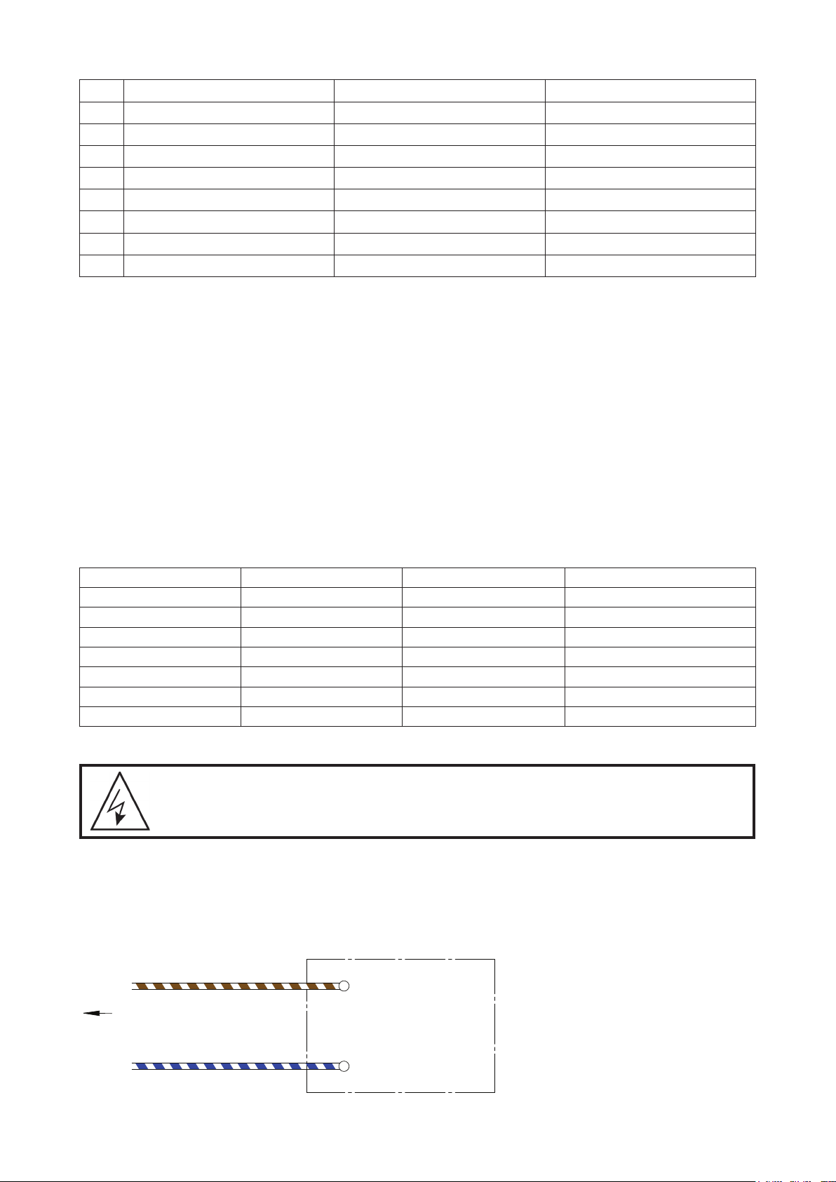
Pin Funktion T-568A T-568B
1 RS485 +ve grün/weiß orange/weiß
2 RS485 -ve Grün Orange
3 Digitaleingang 3 orange/weiß grün/weiß
4 Analogeingang Blau Blau
5 0 VDC Masse Blau/Weiß Blau/Weiß
6 Digitaleingang 2 Orange Grün
7 Digitaleingang 1 braun/weiß braun/weiß
8 24V Braun Braun
Prüfen Sie, dass das Kabel, das Sie benutzen die oben gezeigte Farbkodierung der Pins 1-8 hat. Wenn eine
alternative Farbkodierung benutzt wurde, ist darauf zu achten, dass die Farbe, die zu den einzelnen Pins
gehört, aufgezeichnet wird, um Fehlanschlüsse an der Poolsteuerung oder an der Heizung zu vermeiden.
Wenn ein alternatives Kabel benutzt wird, stellen Sie sicher, dass der Analogeingang und die Masse
miteinander verdreht sind.
Der 24V-Anschluss ist nur als Referenz für die digitalen Eingänge zu verwenden - versorgen Sie KEINE
externen Geräte von dieser Versorgungsschiene mit Strom.
Digitale Steuerungseingänge
Die 3 digitalen Eingänge erlauben das Außerkraftsetzen der Drehzahleinstellung des Wählschalters. Um
einen dieser Eingänge zu setzen:
• Verbinden Sie eine isolierte 24V Stromversorgung zwischen der Gleichstrom-Masse und dem
Digitaleingangs-Pin
• Oder verbinden Sie die vertauschten Kontakte eines Relais zwischen dem 24V-Pin und dem digitalen Eingang
Die festen Drehzahlen (in Proportion zur vollen Drehzahl) sind:
Eingang 1 (Pin 7) Eingang 2 (Pin 6) Eingang 3 (Pin 3) Ausgangsgeschwindigkeit
0 0 0 Wählen
0 0 24V 33%
0 24V 0 50%
0 24V 24V Rückspülung
24V 0 0 100%
24V 0 24V 67%
24V 24V 0 83%
Schnittstellenequipment für die SilensorPro SP400BT
WARNUNG! Ein qualizierter Elektriker wird benötigt um die unten gezeigten Arbeiten
durchzuführen.
SilensorPRO SP400BT kann mit anderem Equipment gesteuert werden um sie auf maximale Drehzahl zu
schalten (oder jede andere voreingestellte Drehzahl, siehe Abschnitt 8 für Details). Das ist um maximale
Effizienz der Pumpe zu erreichen, zum Beispiel beim Nutzen eines Gasheizgeräts oder einer Wärmepumpe.
Wenn das Gerät über einen isolierten 18- 24V DC-Signalausgang verfügt, verbinden Sie einfach Pin 7 mit
24V DC positiv und Pin 5 mit Gleichstrom-Masse, wie in der folgenden Abbildung gezeigt:
Controlling Equipment
Pin7 (Brown/White)
To RJ45 Socket of VSD Pump
Pin5 (Blue/White)
+ 18 ~ 24V DC
DC Ground
Deutsch
35
Page 36

Wenn das Steuergerät nicht über einen 18-24 VDC Spannungsausgang wie oben beschrieben verfügt und
über einen 24 VAC, 230 VAC, 12 VAC oder 12 VDC etc. Signalausgang verfügt, kann ein geeignetes Relais
(die Spulenspannung muss gleich der Signalausgangsspannung des Steuergeräts sein) verwendet werden,
um diese Aufgabe wie oben erwähnt und in der folgenden Abbildung dargestellt zu erfüllen:
Controlling Equipment
Pin7 (Brown/White)
To RJ45 Socket of VSD Pump
Pin8 (Brown)
Relay (Dry)
Contact
Relay Coil, must be
the same voltage
as the equipment
signal output
Wenn das Steuergerät bereits über den Relaisausgang (potentialfreier Kontakt) zur Steuerung verfügt, ist ein
zusätzliches Relais nicht erforderlich, sondern Sie müssen lediglich Pin 7 (braun/weiß) und Pin 8 (braun) an
die potentialfreien Kontakte anschließen, wie im linken Teil des obigen Diagramms dargestellt.
Analoger Steuereingang
Die Drehzahlregelung kann auch durch den Anschluss eines 0-10 VDC-Signals am Eingang an Pin 4 (Masse
an Pin 5) erreicht werden. Sobald ein Signal über 0V registriert wird, hat dieser Eingang Vorrang vor den
Wahleinstellungen. Zum Beispiel ändert 10 VDC die Pumpendrehzahl der Pumpe auf 100%, 5 VDC die
Pumpendrehzahl auf 50%, usw.
Controlling Equipment
+ 0~ 10 V DC Signal Output
Pin4 (Blue)
To RJ45 Socket of VSD Pump
Pin5 (Blue/White)
of controlling equipment
DC Ground
8. TECHNISCHE DATEN
Modell
Füllhöhe (m)
U/min
Schutzart (IP)
Isolationsklasse
Spannung (V)
Wechselstromfrequenz (Hz)
Motoreingangsleistung: (W)
Betriebsgrenzwerte
Max. Wassertemperatur:
Max. Umgebungstemperatur:
SP200BT SP400BT
20 26
Drehzahl 1 – 10: 1500 – 3600 Drehzahl 1 – 10: 1050 – 3100
Rückspülgeschwindigkeit: variabel
45
F
220 – 240 VAC
50/60 Hz
Drehzahl 1: 128 Drehzahl 1: 126
Drehzahl 5: 524 Drehzahl 5: 728
Drehzahl 10: 1111 Drehzahl 10: 1639
Rückspülgeschwindigkeit: variabel
40° C 40° C
50°C 50°C
36
Deutsch
Page 37
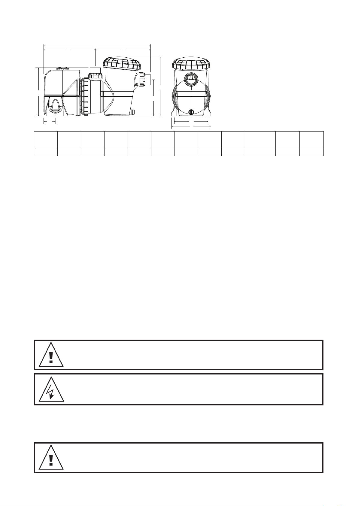
Abmessungen
C
B
D
A
E
A
305mm 670mm 320mm 350mm 65mm 230mm 380mm 200mm 250 mm 10mm 50/63 14
9.
VERWENDUNG DER SILENSOPRO MIT EINEM SALZWASSER-CHLORINATOR
B C
D E F G H I
G
F
H
I
Durchmesser
der
Montagelöcher
Einlass/
Auslass
PVC
Netto-
gewicht
(kg)
Chlorinatoren benötigen eine minimale Durchflussmenge durch die Chlorinator-Zelle für die höchste
Effizienz und Lebenszeit. Bitte beachten Sie die Anleitung Ihres Chlorinators als Referenz für den von Ihrem
Poolsystem benötigten Durchfluss. Vergewissern Sie sich, dass die Durchflussmenge ausreichend ist, um
Ihre Chlorinatorzellenplatten zu jeder Zeit des Betriebs vollständig zu bedecken.
10. BETRIEB EINES BECKEN-SAUGREINIGERS
Bevor Sie einen Poolreiniger für die Verwendung mit SilensorPRO installieren oder kaufen, ist es wichtig, die
Mindestdurchflussmengen zu kennen, die für einen effektiven Betrieb erforderlich sind.
Zum Betrieb eines Becken-Saugreinigers:
• Aktivieren Sie die Einstellung High Flow (10) und lassen Sie die Pumpe ca. 2 Minuten lang laufen. Sie
werden wissen, dass die Pumpe angesaugt hat, wenn Sie einen starken Wasserdurchfluss durch den
durchsichtigen Deckel des Blattkorbes sehen können.
• Wenn die gesamte Luft aus dem Laubkorb entweicht, schließen Sie den Poolreinigungsschlauch fest an
die Skimmer-Platte oder eine spezielle Wandabsaugung an.
• Wählen Sie die Drehzahleinstellung, die die beste Leistung Ihres Becken-Saugreinigers ermöglicht. Die
Drehzahlstufen 3 bis 7 sollten für die meisten Reiniger ausreichend sein, aber wenn der Reiniger eine
bessere Leistung benötigt, wählen Sie die Drehzahlstufen 7 bis 10.
• Der Reiniger sollte nur so lange angeschlossen werden, wie es für die Reinigung der Beckenoberfläche
erforderlich ist. Wenn die Reinigung abgeschlossen ist, trennen Sie den Reiniger und entfernen Sie die
Skimmer-Platte aus dem Skimmer-Kasten.
• Reaktivieren Sie die effizienteste Drehzahleinstellung für die tägliche Filtration. Drehzahlstufen 1 bis 4
werden empfohlen.
HINWEIS: Um eine optimale Energieefzienz Ihres SilensorPRO zu erreichen, lassen Sie
den Becken-Saugreiniger NICHT angeschlossen, wenn keine Reinigung erforderlich ist.
HINWEIS: Wenn SilensorPRO mit einer Zeitschaltuhr oder einer anderen automatischen
Steuerung verbunden ist, sollte die Verkabelung von einem qualizierten Techniker
entfernt werden.
• Schließen Sie die Wasserventile am Beckenrücklauf und an der Einlassleitung der SilensorPRO;
• Entfernen Sie die Druck- und Saugrohrverschraubungen und achten Sie darauf, dass die O-Ringe nicht
verloren gehen;
• Verschieben Sie die Verrohrung mit den Fassverschraubungen, bis SilensorPRO frei gezogen werden kann.
HINWEIS: Bei Anfragen zu Ihrem SilensorPRO geben Sie bitte unbedingt die
Modellnummer auf dem Typenschild des Motors an.
Deutsch
37
Page 38

11. FEHLERBEHEBUNG
Wenn die Pumpe läuft, aber kein Wasserfluss vorhanden ist oder der Wasserfluss reduziert wird,
kann dies an folgenden Bedingungen liegen:
• Der Filter muss rückgespült werden oder ist verstopft. Für mehr Informationen dazu schauen Sie in den
entsprechenden Abschnitt in der Betriebsanleitung des Filters;
•
Die Pumpe ist nicht vorgefüllt. Füllen Sie sie erneut vor, wie in der Anleitung unter „Starten der Pumpe“ beschrieben;
• Es gibt Luftlecks in den Saugleitungen. Überprüfen Sie alle Leitungen und beseitigen Sie Lecks, überprüfen
Sie auch, dass der Siebkorbdeckel nicht lose ist. Luftblasen im Wasser, die in das Becken zurückfließen,
werden durch ein Leck im Ansaugweg zur Pumpe erzeugt, das Luft in die Rohrleitungen lässt.
• Eine undichte Dichtung der Pumpenwelle kann auch den Betrieb verhindern. Wasser auf dem Boden unter
der Pumpe kann darauf hinweisen.
• Die Pumpe ist nicht in der Lage, Wasser aus dem Becken zu pumpen. Überprüfen Sie, dass die Ventile
zur Pumpe vollständig geöffnet sind und der Wasserpegel des Beckens bis zum Skimmer-Kasten reicht.
Normalerweise reicht ein Wasserstand bis zur halben Höhe des Skimmer-Kastens aus;
• Verstopfung in der Rohrleitung oder Pumpe. Entfernen Sie den Siebkorb und prüfen Sie, ob der Eingang
zum Flügelrad der Pumpe verstopft ist. Überprüfen Sie den Skimmer-Kasten auf Verstopfungen.
Wenn die Pumpe nicht läuft, können folgende Szenarien zutreffen:
• Strom ist nicht angeschlossen. Ausschließlich bei 220-240 Volt-Anschlüssen kann mit einem mobilen Gerät
geprüft werden, dass Strom verfügbar ist. Überprüfen Sie auch die Sicherungen und den Hauptschalter
der Stromversorgung;
• Automatische Überlastung wird ausgelöst. Die Pumpe hat eine eingebaute thermische Überlast, die sich
nach dem Abkühlen des Motors nach einer zeitweisen Überhitzung automatisch zurücksetzt. Überprüfen
Sie die Ursache der Auslösung der Überlast und beheben Sie sie. Setzen Sie die Pumpe zurück, indem
Sie die Stromversorgung 30 Sekunden lang ausschalten;
• Blockierung der Drehung der Pumpe durch eine Blockage.
12. SILENSORPRO VON ROHRLEITUNG ENTFERNEN
Sollte es notwendig sein, SilensorPRO zu entfernen, befolgen Sie bitte diese Anweisungen:
• Schalten Sie das Gerät aus und ziehen Sie den Stecker aus der Steckdose;
• Die Fassverschraubung an der Vorder- und Oberseite der Pumpe lösen, und die Pumpe von der
Rohrleitung entnehmen;
• Die Pumpe aus der Position schieben.
13. WASSERQUALITÄT
EMPFOHLENE CHEMISCHE ZUSÄTZE FÜR DAS POOLWASSER
POOLWASSER
AUSGEWOGENHEIT
Idealer Wert/Bereich 1 – 3
Zum Erhöhen
Zum Vermindern
Freies Chlor
(ppm)
Chlorinator-
Ausgabeleistung
erhöhen. Chlor
zugeben.
Filtrationszeit
erhöhen.
pH
Beton- und
gekachelte Pools:
7,4-7,6
Andere
Oberächen:
7,2-7,4
Puffer oder Soda
atriumcarbonat)
zugeben
Muriasäure
zugeben
Gesamt-Alkalinität
TA
(ppm)
Beton- und
gekachelte Pools –
80-120.
Andere
Oberächen –
125-150
Natrium-Bikarbonat
hingeben
Muriasäure
zugeben
oder trockene
Säure
Kalkhärte
(ppm)
Beton- und
gekachelte Pools –
200-275.
Andere Oberächen
–
100-225
Calciumchlorid
zugeben
Zum Verdünnen Pool
zum Teil entleeren
und mit Wasser
geringerer Härte
nachfüllen
Stabilisator Cyanursäure
(ppm)
25 – 50 4500 – 6000
Cyanursäure
zugeben
Zum
Verdünnen
Pool zum Teil
entleeren und
nachfüllen
Optimaler
Salzgehalt
(ppm)
Salz zugeben
Zum
Verdünnen
Pool zum Teil
entleeren
und nachfüllen
Prüfhäugkeit Wöchentlich Wöchentlich Wöchentlich Wöchentlich Regelmäßig Regelmäßig
Deutsch
38
Page 39

Routinemäßige Wartungsarbeiten - um die Lebensdauer Ihrer Poolausrüstung und
die persönliche Sicherheit zu maximieren, verwenden Sie diese Checkliste einmal pro
Woche. Schalten Sie zuerst die Pumpe aus.
a. Stellen Sie sicher, dass sich alle Manometer im Betriebszustand benden und der
Betriebsdruck innerhalb der auf dem Produkt angegebenen Grenzen liegt.
b. Vergewissern Sie sich, dass jeder Ansaug- und Hauptablass mit einer Abdeckung
versehen ist, die sicher befestigt ist und sich in einem sicheren Betriebszustand
bendet.
c. Stellen Sie sicher, dass alle Abdeckungen des Skimmers sicher befestigt sind und
sich in einem sicheren Betriebszustand benden. Diese sollten alle 3 bis 4 Jahre
ausgetauscht werden.
d. Entfernen Sie alle Hindernisse oder Fremdkörper von der Hauptablaufabdeckung.
e. Stellen Sie sicher, dass die Skimmer-Körbe und die Haar- und Fusseltöpfe der Pumpe
mindestens einmal pro Woche von Laub und Schmutz befreit werden.
f. Entfernen Sie Hindernisse und brennbare Stoffe rund um den Pumpenmotor.
g. Vergewissern Sie sich, dass alle Kabelverbindungen sauber und alle Kabel und
elektrischen Geräte in gutem Zustand sind. Beschädigte Leitungen müssen von
einem qualizierten Elektriker repariert oder ersetzt werden, sobald Schäden
festgestellt werden.
h. Überprüfen Sie den Wasserhaushalt und die Desinfektionsmittelstände in Ihrem
örtlichen Poolzubehörgeschäft.
DIE SPANNUNGSANSCHLÜSSE UND DIE VERDRAHTUNG DER ANLAGE MÜSSEN VON
EINEM ZUGELASSENEN ELEKTRIKER VORGENOMMEN WERDEN.
GEFAHR Gefährlicher Sog. Blockieren Sie den Wassereintritt in das Filtersystem nicht
mit irgendeinem Teil Ihres Körpers, da der Druck die Haare oder Körperteile einfangen
und schwere Verletzungen oder den Tod verursachen kann. Den Absaugstutzen nicht
blockieren.
Schalten Sie die Pumpe sofort aus, wenn jemand gefangen ist.
Verwenden oder betreiben Sie keine Schwimmbäder, Spas oder Spa-Bäder, wenn
eine Saugabdeckung gebrochen ist, fehlt oder lose ist. In jede Pumpe müssen zwei
Saugabdeckungen und -Einlässe eingebaut werden, um ein Einklemmen des Saugers
zu vermeiden.
Gemäß AS/NZS60335.2.41 sind wir verpichtet, Sie zu informieren, dass dieses Gerät
nicht von Kindern oder gebrechlichen Personen bedient und von Kindern nicht als
Spielzeug genutzt werden darf.
VORSICHT! Geben Sie keine Chemikalien direkt in den Skimmer. Das Hinzufügen
von unverdünnten Chemikalien kann die Pumpe und den Filter beschädigen und zum
Verlust der Garantie führen.
39
Deutsch
Page 40

Davey-Garantie
Davey Water Products räumt die Gewährleistungsansprüche ein, die nach dem örtlichen Landesrecht nicht
ausgeschlossen werden können. Sie haben Anspruch auf Ersatz oder Rückerstattung bei einem größeren Ausfall, und
Ersatz für jeden anderen vernünftigerweise vorhersehbaren Verlust oder Schaden. Sie haben auch das Recht, die Ware
reparieren oder ersetzen zu lassen, wenn die Ware nicht von akzeptabler Qualität ist und der Fehler keinen größeren
Fehler darstellt.
Davey Water Products Pty Ltd (Davey) in 6 Lakeview Drive Scoresby VIC 3179, Australien gewährt die folgende
Garantie in Bezug auf dieses Produkt. Davey garantiert, dass das Produkt vorbehaltlich der nachstehenden
Ausschlüsse und Einschränkungen für einen Zeitraum von 24 Monaten ab Kaufdatum (Garantiezeit) frei von Materialund Verarbeitungsfehlern ist.
Wenn vor Ablauf der Garantiezeit ein Fehler am Produkt auftritt und Davey feststellt, dass das Produkt einen Materialoder Verarbeitungsfehler aufweist, wird Davey nach eigenem Ermessen entweder:
1. das Produkt oder den defekten Teil des Produkts kostenlos ersetzen oder reparieren; oder
2. das Produkt oder den defekten Teil des Produkts kostenlos von einer qualifizierten Werkstatt reparieren oder
ersetzen zu lassen.
Davey behält sich das Recht vor, defekte Teile des Produkts durch Teile oder Komponenten ähnlicher Qualität, Güte
und Zusammensetzung zu ersetzen, wenn ein identisches Teil oder eine identische Komponente nicht verfügbar ist. Zur
Reparatur vorgelegte Waren werden u.U. nicht repariert, sondern durch instandgehaltene Waren desselben Typs ersetzt.
Gewährleistungsansprüche:
1. Wenn ein Fehler auftritt, der unter diese Garantie fällt, schlägt Davey zunächst vor, dass Sie sich an den DaveyHändler wenden, bei dem Sie das Produkt gekauft haben. Alternativ können Sie auch: den Davey-Kundendienst in
Australien unter 1300 367 866 oder in Neuseeland unter 0800 654 333 anrufen, einen Brief an Davey unter der oben
genannten Adresse, oder eine E-Mail an sales@davey.com.au senden.
2. Jedem Gewährleistungsanspruch sind ein Kaufbeleg und Angaben zum Mangel beizufügen.
3. Bei Erhalt Ihrer Anfrage wird sich Davey bemühen, Ihre Schwierigkeiten zu beheben oder Sie im Falle eines
mangelhaften bzw. defekten Produkts zu beraten, wie Sie Ihr Produkt reparieren lassen bzw. ein Ersatzprodukt
oder eine Rückerstattung erhalten können.
4. Diese Garantie beschränkt sich auf Material- oder Verarbeitungsfehler des Produkts und erstreckt sich nicht auf
Verschleißteile oder den Austausch von Teilen wegen gewöhnlicher Abnutzung oder Alterung.
Ausschlüsse:
Die Garantie gilt nicht, wenn:
Wenn das Produkt von einer anderen Person als Davey oder einer autorisierten Werkstatt modifiziert, repariert oder
1.
gewartet wurde.
2. Davey nach der Prüfung keinen Fehler am Produkt feststellen kann.
3. Das Produkt nicht für den Zweck verwendet wurde, für den es entwickelt wurde.
4. Das Produkt ungewöhnlichen Bedingungen bezüglich Temperatur, Wasser, Feuchtigkeit, Druck, mechanischer
Belastung oder ähnlichem ausgesetzt wurde.
5. Der Käufer nicht originale oder nicht zugelassene Teile und Zubehörteile verwendet oder eingebaut hat.
6. Der Produktfehler durch falschen Gebrauch, Missbrauch, Vernachlässigung oder Unfall entstanden ist.
7. Der Produktfehler darauf zurückzuführen ist, dass der Käufer das Produkt nicht ordnungsgemäß gewartet oder
verwendet hat.
8. Der Schaden durch die Verwendung von Chemikalien oder Reinigungsmitteln verursacht wurde, die nicht von
Davey zugelassen sind.
Sollte Ihr Davey-Produkt nach Ablauf der Garantiezeit repariert oder gewartet werden müssen, wenden Sie sich bitte
an Ihren nächsten Davey-Händler, oder telefonisch oder per E-Mail an das Davey-Kundendienstzentrum. Für eine
vollständige Liste der Davey-Vertragshändler besuchen Sie bitte unsere Website.
INTERNATIONAL
Hauptniederlassung in
Ph: +613 9730 9124
Fax: +613 9753 4248
Email: export@davey.com.au
Davey Water Products Pty Ltd
Member of the GUD Group
ABN 18 066 327 517
AUSTRALIEN
Hauptniederlassung
6 Lakeview Drive,
Scoresby, Australia 3179
Ph: 1300 232 839
Fax: 1300 369 119
Email: sales@davey.com.au
Website: davey.com.au
® Davey is a trademark of Davey Water Products Pty Ltd. © Davey Water Products Pty Ltd 2019.
Website: davey.com.au
EUROPA
ZAC des Gaulnes
355 Avenue Henri Schneider
69330 Meyzieu, France
Ph: +33 (0) 4 72 13 95 07
Fax: +33 (0) 4 72 33 64 57
Email: info@daveyeurope.eu
Website: daveyeurope.eu
NEUSEELAND
7 Rockridge Avenue,
Penrose, Auckland 1061
Ph: 0800 654 333
Fax: 0800 654 334
Email: sales@dwp.co.nz
Website: daveynz.co.nz
NORDAMERIKA
Ph: +1 866 328 7867
Email: export@davey.com.au
Website: daveyusa.com
MITTLERER OSTEN
Ph: +971 50 6368764
Fax: +971 6 5730472
Email: info@daveyuae.com
Website: daveyuae.com
40
P/N 403308-1
Page 41

SilensorPRO SP200BT e SP400BT
Pompa per piscina
Istruzioni di montaggio e
di utilizzo
50/60 Hz
SP200BT
Consultare il sito Web Davey del proprio Paese nonché il retro del presente
documento per eventuali aggiornamenti alle informazioni del prodotto.
Si prega di trasmettere le presenti istruzioni all'operatore di questa apparecchiatura.
SP400BT
Italiano
Page 42

Complimenti per l’acquisto della pompa SilensorPRO SP200BT o SP400BT, un prodotto di alta qualità. Tutti i
componenti sono stati progettati e realizzati per assicurare un funzionamento affidabile e privo di problemi.
Indice:
1. INSTALLAZIONE DELLA POMPA A VELOCITÀ VARIABILE DAVEY ......................................................43
Collegamenti elettrici ................................................................................................................................43
Connessione delle tubazioni .....................................................................................................................43
2. SCHEMA DI INSTALLAZIONE TIPICO ....................................................................................................45
3. SPECIFICHE SULLE PRESTAZIONI .......................................................................................................45
3.1 Prestazioni idrauliche della pompa SP200BT .....................................................................................45
3.2 Specifiche elettriche della pompa SP200BT .......................................................................................46
3.3 Prestazioni idrauliche della pompa SP400BT .....................................................................................46
3.4 Specifiche elettriche della pompa SP400BT .......................................................................................46
4. MANUALE D’USO ....................................................................................................................................47
Risparmio energetico con SilensorPRO ...................................................................................................47
Controlli prima dell’avviamento .................................................................................................................47
Funzionamento a basso consumo ............................................................................................................48
Linee guida per le ore di funzionamento consigliate della pompa ............................................................48
Svuotamento del cestello del filtro ............................................................................................................49
Manutenzione ordinaria ............................................................................................................................49
5. CARATTERISTICHE E FUNZIONALITÀ ..................................................................................................50
Indicatore LED multicolore ........................................................................................................................50
Tecnologia del ciclo della velocità di controlavaggio ................................................................................. 50
Trasmissione completa a frequenza variabile con selettore di velocità selezionabile facile da usare ......50
Grande filtro lanugine da 4,5 litri ...............................................................................................................50
Design brevettato raffreddato ad acqua per un funzionamento fluido e super silenzioso ........................50
Compensazione flusso/velocità costante della pompa SP400BT .............................................................50
Porta di comunicazione RJ45 resistente alle intemperie della pompa SP400BT
(consultare la sezione 7 per i dettagli di collegamento) ............................................................................50
6. FUNZIONALITÀ BLUETOOTH .................................................................................................................51
Impostazione della app Bluetooth .............................................................................................................51
Associazione di un dispositivo alla pompa ...............................................................................................51
Timer esterno/Cloratore ............................................................................................................................51
Modalità di programmazione ....................................................................................................................51
Impostazione di un programma ................................................................................................................52
Impostazioni ..............................................................................................................................................52
Velocità di adescamento / Velocità massima ............................................................................................ 52
Controlavaggio ..........................................................................................................................................53
Timer esterno presente .............................................................................................................................53
Funzione di disconnessione .....................................................................................................................53
Ripristino alle impostazioni di fabbrica ......................................................................................................53
Ricerca guasti della pompa ......................................................................................................................53
7. IMPOSTAZIONI AVANZATE DELLA POMPA SP400BT ...........................................................................54
Panoramica della connessione AUX esterna ............................................................................................54
Ingressi di controllo digitale ......................................................................................................................55
Interfacciamento dell'apparecchiatura con SilensorPRO SP400BT .........................................................55
Ingressi di controllo analogico ..................................................................................................................56
8. SPECIFICHE TECNICHE .........................................................................................................................56
9. USARE LA POMPA SILENSORPRO CON UN CLORATORE DI ACQUA SALATA .................................57
10. FUNZIONAMENTO DEL PULITORE PER PISCINE AD ASPIRAZIONE .................................................57
11. RISOLUZIONE DEI PROBLEMI ...............................................................................................................58
12. RIMOZIONE DELLA POMPA SILENSORPRO DALLE TUBAZIONI ........................................................58
13. QUALITÀ DELL'ACQUA ...........................................................................................................................58
14. GARANZIA DAVEY ...................................................................................................................................60
42
Italiano
Page 43

1. INSTALLAZIONE DELLA POMPA A VELOCITÀ VARIABILE DAVEY
La pompa SilensorPRO deve essere posizionata il più vicino possibile all'acqua e montata su una base
stabile in una posizione ben drenata, sufficientemente alta da evitare qualsiasi allagamento. È responsabilità
dell'installatore/proprietario posizionare la pompa in modo che la targhetta identificativa possa essere
facilmente letta e che la pompa SilensorPRO possa essere facilmente accessibile per l'assistenza. Si
raccomanda che la pompa SilensorPRO sia protetta dalle intemperie. Gli involucri devono essere ventilati
per evitare l'accumulo di condensa.
La mancata osservanza delle presenti istruzioni e il mancato rispetto di tutti i codici
applicabili possono causare gravi lesioni personali e/o danni alle cose.
Questa pompa richiede esperienza professionale per l'installazione e la manutenzione.
L'installazione di questo prodotto deve essere eseguita da una persona esperta nei
requisiti idraulici della piscina e che segua le istruzioni di installazione fornite in
questo manuale.
Collegamenti elettrici
INFORMAZIONI IMPORTANTE La pompa SilensorPRO presenta un doppio isolamento
del circuito dell’acqua. Se è necessario una struttura di collegamento equipotenziale,
allora viene fornito un punto di collegamento equipotenziale. (Fare riferimento a statuti
e/o normative locali per le norme di cablaggio equivalenti ad AS/NZ 3000).
ATTENZIONE! Nell'interesse della sicurezza, consigliamo di installare tutte le marche e
i tipi di pompe per piscine in conformità a AS/NZS 3000, note come norme di cablaggio
nazionali o standard locali equivalenti. Tutte le installazioni elettriche devono essere
eseguite da un elettricista qualicato. Davey raccomanda che tutte le installazioni siano
dotate di dispositivi di protezione dalla dispersione verso terra o di corrente residua. La
corrente di esercizio residua nominale non deve superare i 30 mA.
AVVERTENZA! Assicurarsi che un interruttore di isolamento elettrico sia facilmente
accessibile in modo che la pompa possa essere spenta in caso di emergenza.
F NFC C 15-100 GB BS7671:1992
D DIN VDE 0100-702 EW EVHS-HD 384-7-702
A OVE 8001-4-702 H MSZ 2364-702:1994/MSZ 10-533 1/1990
E UNE 20460-7-702 1993, REBT ITC-BT-31 2002 M MSA HD 384-7-702.S2
IRL IS HD 384-7-702 PL PN-IEC 60364-7-702: 1999
I CEI 64-8/7 CZ CSN 33 2000 7-702
LUX 384-7.702 S2 SK STN 33 2000-7-702
NL NEN 1010-7.702 SLO SIST HD 384-7-702.S2
La pompa SilensorPRO è adatta per il collegamento a un’alimentazione nominale da 220 – 240 volt 50/60
Hz ed è dotata di cavo flessibile. Se una presa di corrente non è disponibile entro 3 metri dalla pompa,
potrebbe essere necessario che l'elettricista provveda a un'adeguata presa di corrente tripolare in un luogo
sicuro e asciutto. Le prolunghe non sono sicure intorno alle piscine e dovrebbero essere evitate. Se il cavo
di alimentazione della pompa SilensorPRO è danneggiato, deve essere sostituito da Davey o da un agente
autorizzato con ricambi originali Davey.
La pompa SilensorPRO incorpora il rilevamento del sovraccarico del motore progettato per proteggere
il motore dal surriscaldamento. Se il motore si riscalda troppo durante il funzionamento, la sua velocità
operativa si ridurrà per portarlo entro una temperatura operativa accettabile e quindi accelererà fino alla
velocità impostata originariamente.
Per ripristinare il motore, spegnere l'alimentazione per 30 secondi e quindi rialimentare dall'interruttore di rete.
Italiano
43
Page 44

Connessione delle tubazioni
Figure 1.2
152mm
MINIMUM
76mm
MINIMUM
Suction line
50/63mm
Return to
Pool
50/63mm
Return to
Le valvola a sfera sono fornite per il collegamento alle condutture dalla piscina. Le pompe sono progettate
per accettare raccordi in PVC da 50/63 mm.
INFORMAZIONI IMPORTANTISe la pompa SilensorPRO e il ltro si trovano sotto il livello
dell'acqua della piscina, è necessario installare valvole di intercettazione nel tubo tra la
pompa e la scatola del separatore e nel tubo di ritorno dal ltro alla piscina. Quando si
collega il tubo di scarico, assicurarsi che le tubazioni non interferiscano con il selettore
della velocità delle pompe. Le valvole a sfera devono essere serrate a mano. Non sono
richiesti sigillanti, colle o siliconi.
I raccordi sulla pompa SilensorPRO sono realizzati in ABS. Alcuni composti per giunzioni
in PVC sono incompatibili con l'ABS. Vericare l'idoneità dei composti prima dell'uso.
L'uso di qualsiasi tubo più piccolo di quelli sopra specificati non è raccomandato. Le tubazioni di aspirazione
devono essere prive di ogni perdita d'aria e da eventuali gobbe e cavità che causano difficoltà di aspirazione.
Per ottenere la massima efficienza, la pompa SilensorPRO deve essere installata in modo tale da limitare
al massimo flussi d’acqua turbolenti. Come mostrato nella figura 1.1, non installare un gomito a 90° a meno
di 250 mm dal raccordo. Le valvole di intercettazione, utilizzate nei casi in cui l'apparecchiatura si trova al di
sotto del livello dell'acqua della piscina, devono essere installate a non più di 250 mm dal raccordo. Questo
aiuterà a ottenere un regime laminare.
Figure 1.1
250mm
ELBOW
Suction line
50/63mm
Pool
50/63mm
La tubazione di scarico dall'uscita della pompa SilensorPRO deve essere collegata alla connessione di
ingresso sul filtro della piscina (di solito sulla valvola di controllo del filtro). Come mostrato nella figura 1.2,
assicurare uno spazio sufficiente sopra la pompa per non interferire con il selettore di velocità della pompa
SilensorPRO. Utilizzare una valvola di ritegno nella linea di scarico quando si utilizza questa pompa per
qualsiasi applicazione in cui vi sia un'altezza significativa verso l'impianto idraulico dopo la pompa.
Figure 1.2
Return to
Pool
50/63mm
152mm
MINIMUM
Suction line
50/63mm
76mm
MINIMUM
Assicurarsi di installare le valvole di ritegno durante l'installazione con un'altra pompa. Questo aiuta a
prevenire la rotazione inversa della girante e del motore.
AVVERTENZA! L'aspirazione della pompa è pericolosa e può intrappolare e annegare
o sventrare i bagnanti. Non bloccare l'aspirazione. Non far funzionare piscine, spa o
bagni termali se un coperchio di aspirazione è rotto, mancante o allentato. Per evitare
l'intrappolamento per effetto dell’aspirazione, devono essere previsti due coperchi di
aspirazione e ingressi in ogni pompa.
44
Italiano
Page 45

2. SCHEMA DI INSTALLAZIONE TIPICO
ProMaster - PM200SV
Performance
Pool pump Media Filter
3. SPECIFICHE SULLE PRESTAZIONI
3.1 Prestazioni idrauliche della pompa SP200BT
25
20
15
Total Head ( m )
10
5
Dial position No. 10
Dial position No. 9
Dial position No. 8
Dial position No. 7
Dial position No. 6
Dial position No. 5
Dial position No. 4
Dial position No. 3
Dial position No. 2
Dial position No. 1
0
0 50 100 150 200 250 300 350 400
Flow ( lpm )
0
036 9 12 15 18 21 24
3
Flow ( m
45
/h )
Italiano
Page 46

3.2 Specifiche elettriche della pompa SP200BT
450
Velocità
Impostazione
Selettore 1 0,17 128 0,12 90
Selettore 2 0,28 207 0,19 145
Selettore 3 0,39 293 0,27 205
Selettore 4 0,53 398 0,37 279
Selettore 5 0,70 524 0,49 367
Selettore 6 0,87 655 0,61 459
Selettore 7 1,08 807 0,75 565
Selettore 8 1,25 936 0,87 655
Selettore 9 1,44 1.078 1,01 755
Selettore 10 1,48 1.111 1,04 778
hp W hp W
Ingresso Uscita
3.3 Prestazioni idrauliche della pompa SP400BT
25
Dial position No. 10
Dial position No. 9
Dial position No. 8
20
15
Dial position No. 7
Dial position No. 6
Dial position No. 5
Dial position No. 4
Dial position No. 3
Dial position No. 2
Dial position No. 1
Total Head ( m )
10
5
0
0 50 100 150 200 250 300 350 400
Flow ( lpm )
0
036 9 12 15 18 21 24 27
3
Flow ( m
/h )
3.4 Specifiche elettriche della pompa SP400BT
Velocità
Impostazione
Selettore 1 0,17 126 0,12 89
Selettore 2 0,28 210 0,20 147
Selettore 3 0,46 347 0,32 243
Selettore 4 0,70 522 0,49 366
Selettore 5 0,97 728 0,68 510
Selettore 6 1,22 913 0,85 639
Selettore 7 1,61 1.211 1,13 848
Selettore 8 1,97 1.478 1,38 1.034
Selettore 9 2,18 1.635 1,59 1.191
Selettore 10 2,19 1.639 1,62 1.212
hp W hp W
Ingresso Uscita
46
Italiano
Page 47

4. MANUALE D’USO
Questa pompa SilensorPRO è abilitata al Bluetooth, quindi sarà possibile impostare e controllare le funzioni
della pompa dal proprio dispositivo intelligente. Il Bluetooth è un protocollo di comunicazione wireless che
consente la comunicazione tra dispositivi. Questa funzione è supportata da qualsiasi dispositivo in grado di
scaricare un'app da iOS o dall'App Store di Android.
Leggere queste istruzioni nella loro interezza prima di accendere questa pompa. Se non si è sicuri di queste
istruzioni di installazione e uso, contattare Davey come indicato sul retro di questo documento.
Ogni pompa SilensorPRO viene accuratamente testata sull'acqua in base a un numero di parametri di
portata, pressione, tensione, corrente e prestazione meccanica. L'avanzata tecnologia di produzione delle
pompe di Davey fornisce prestazioni di pompaggio affidabili ed efficienti che durano a lungo.
Risparmio energetico con SilensorPRO
La pompa a velocità variabile Davey è una pompa super efficiente che utilizza un motore AC a variazione
continua di ultima generazione e molto intelligente, che offre livelli di rumore più bassi, costi operativi ridotti e
minori emissioni di gas serra rispetto alle pompe da piscina tradizionali.
Grazie alla sua capacità di funzionare a velocità inferiori rispetto alle pompe convenzionali, la vostra pompa
subirà anche meno usura meccanica per effetto delle minori sollecitazioni sui componenti meccanici interni.
Ottenere un pompaggio efficiente dal punto di vista energetico è facile. Basta far funzionare la pompa di
filtrazione a una velocità inferiore, ma per un periodo di tempo più a lungo rispetto a una pompa a velocità
fissa convenzionale così da "rinnovare" l'acqua della piscina per un'adeguata filtrazione e igiene. Il risultato è
un minore consumo di energia e costi operativi inferiori fino al 70%.
La pompa SilensorPRO dispone di regolazione della velocità, così da poter variare la velocità di ricircolo
dell'acqua della piscina o della spa. Le velocità possono essere regolate per alimentare un pulitore da
piscina di aspirazione, un sistema di pulizia a pavimento e riscaldatori per piscine. È possibile selezionare
un'impostazione di controlavaggio sulla pompa per eseguire il controlavaggio di un mezzo filtrante.
Cosa aspettarsi per la propria piscina dotata di pompa SilensorPRO (in modalità a risparmio energetico):
• Se la pompa SilensorPRO è in sostituzione di una pompa a motore AC tradizionale, potrebbe essere
necessario farla funzionare più a lungo della precedente pompa a velocità fissa. Questo è NORMALE e
risparmierete energia quando utilizzate le impostazioni di velocità inferiore.
• È anche possibile notare che il manometro sul filtro indica una pressione molto più bassa di quella a cui si
è abituati. Anche questo è NORMALE. La pressione del sistema inferiore è semplicemente il risultato della
velocità e della portata inferiori prodotte dalla pompa.
• Durante il funzionamento alle impostazioni di velocità inferiori si noterà anche una significativa riduzione
del rumore della pompa. Questo è un grande vantaggio in quanto consente di far funzionare la pompa
SilensorPRO al di fuori delle ore di punta delle tariffe elettriche, contribuendo inoltre alla riduzione dei costi
operativi. In più, i vicini vi ringrazieranno.
Molti prodotti della piscina si basano su portate minime per il miglior funzionamento e/o efficienza. Se si
utilizzano impostazioni di flusso basso sulla pompa SilensorPRO (ad es. Velocità 1 - 4), Davey raccomanda
di verificare la compatibilità della velocità o della portata minima richiesta per il funzionamento di
apparecchiature specifiche della piscina come:
• pulitori per piscine con aspirazione;
• generatori di ozono;
• sistemi di riscaldamento;
• celle del cloratore di acqua salata;
• sistemi di pulizia della piscina a pavimento.
Controlli prima dell’avviamento
• L’impostazione della velocità scelta dev’essere compatibile con altre apparecchiature per piscina
• La pompa dev’essere installata in un ambiente sicuro e asciutto
• L'involucro della pompa deve disporre di un drenaggio adeguato in caso di perdite
• Tutti i tappi di trasporto devono essere rimossi
• La tubazione dev'essere correttamente sigillata e supportata
• La pompa dev’essere correttamente innescata
• L'alimentatore dev’essere collegato correttamente
• Tutti i passaggi devono essere stati eseguiti per un funzionamento sicuro
• Il filtro dev'essere stato collegato con un tubo da 50/63 mm
• Le impostazioni del programma (App) devono corrispondere a qualsiasi altro tempo nel sistema
47
Italiano
Page 48

Funzionamento a basso consumo
La pompa SilensorPRO SP200BT permette di impostare la velocità tra 1500 - 3600 giri/minuto. La pompa
SilensorPRO SP400BT permette di impostare la velocità tra 1.050 - 3100 giri/minuto. La velocità 1
corrisponde al livello minimo mentre la velocità 10 al livello massimo.
• La velocità 1 fornisce la velocità più bassa e quindi la massima efficienza energetica e di risparmio.
Funzionamento
Effettuare il controlavaggio del mezzo filtrante
Filtrazione piscina
Funzionamento del pulitore per piscine di aspirazione
Pulire manualmente la vostra piscina
Funzionamento caratteristica delle acque
Funzionamento getto spa
Sistemi di pulizia della piscina a pavimento
Riscaldamento solare della piscina
Impostazione di velocità consigliata
Velocità di controlavaggio
Velocità da 1 a 4
Velocità da 5 a 8
Velocità da 9 a 10
Linee guida per le ore di funzionamento consigliate della pompa
Il tasso di rinnovo tipico delle piscine residenziali deve essere un singolo rinnovo dell'intero volume
dell'acqua della piscina, entro il periodo di un giorno in cui la pompa sarebbe normalmente in funzione. La
tabella seguente fornisce una guida solo per i tempi di funzionamento della pompa mentre è in modalità di
filtrazione al fine di ottenere il tasso di rinnovo minimo:
SilensorPRO SP200BT
Dimensioni della piscina
(litri)
Velocità 1 Velocità 5 Velocità 10
Impostazione della velocità (ore)
20.000 3,3 1,7 1,1
30.000 5,0 2,5 1,7
40.000 6,7 3,3 2,2
50.000 8,3 4,2 2,8
60.000 10,0 5,0 3,3
80.000 13,3 6,7 4,4
100.000 16,7 8,3 5,6
SilensorPRO SP400BT
Dimensioni della piscina
(litri)
20.000 2,4 1,3 0,9
30.000 3,7 2,0 1,4
40.000 4,9 2,7 1,9
50.000 6,1 3,3 2,3
60.000 7,4 4,0 2,8
80.000 9,8 5,3 3,8
100.000 12,3 6,7 4,7
Impostazione della velocità (ore)
Velocità 1 Velocità 5 Velocità 10
48
Italiano
Page 49

Conformemente a EN 60335.1 siamo tenuti a informarvi che questo apparecchio
può essere utilizzato da bambini di età superiore a 8 anni e da persone con ridotte
capacità siche, sensoriali o mentali o con mancanza di esperienza e conoscenza, a
condizione che siano attentamente sorvegliati e istruiti riguardo all'uso in sicurezza
dell'apparecchio, e siano consapevoli dei rischi coinvolti. Tenere sotto controllo i
bambini per assicurarsi che non giochino con il prodotto.
Svuotamento del cestello del filtro
Il cestello del filtro deve essere ispezionato frequentemente attraverso il coperchio trasparente e svuotato
quando è evidente un accumulo di spazzatura. Si devono seguire le seguenti indicazioni.
• Spegnere la pompa
• Svitare il coperchio del cestello del filtro in senso antiorario e rimuoverlo
• Rimuovere il cestello del filtro sollevandolo verso l'alto dal suo alloggiamento
• Svuotare i rifiuti intrappolati dal cestello. Pulire con acqua se necessario
NOTA: MAI battere il cestello di plastica su una supercie dura poiché potrebbe causare
danni.
• Controllare che il cestello del filtro non presenti crepe, riposizionare il cestello dello skimmer nella pompa
se è danneggiato
• Riposizionare il coperchio e assicurarsi che si sigilli sul grande o-ring in gomma. È richiesto solo un saldo
serraggio con le mani. L'o-ring e il filetto possono essere lubrificati con Hydra Slip o prodotti equivalenti.
La mancata esecuzione di una manutenzione regolare può causare danni non coperti da
garanzia.
Manutenzione ordinaria
Per massimizzare la durata della pompa SilensorPRO e la sicurezza personale, utilizzare questa lista
di controllo una volta alla settimana. Assicurarsi che la pompa sia spenta prima di iniziare.
• Assicurarsi che tutti i manometri siano funzionanti e che la pressione operativa sia entro i limiti
specificati sul prodotto
• Assicurarsi che ciascun ingresso di aspirazione e lo scarico principale siano dotati di un coperchio
saldamente fissato e in condizioni di funzionamento sicuro
• Assicurarsi che tutti i coperchi del separatore siano fissati saldamente e in condizioni di funzionamento
sicuro. Questi dovrebbero essere sostituiti ogni 3 o 4 anni
• Rimuovere eventuali ostruzioni o detriti dal coperchio dello scarico principale
• Accertarsi che i cestelli del separatore e della pompa siano privi di foglie e detriti almeno una
volta alla settimana
• Rimuovere ostruzioni e combustibili attorno al motore della pompa
• Assicurarsi che tutti i collegamenti dei cablaggi siano puliti e che tutti i cablaggi e le apparecchiature
elettriche siano in buone condizioni. Il cablaggio danneggiato deve essere riparato o sostituito da un
elettricista qualificato non appena viene rilevato un danno
• Controllare i livelli di equilibrio idrico e dell’igienizzante presso il proprio punto di vendita locale
49
Italiano
Page 50

5. CARATTERISTICHE E FUNZIONALITÀ
La pompa SilensorPRO dispone di diverse funzionalità operative. Queste sono spiegate di seguito.
Indicatore LED multicolore
Utilizzato per identificare le impostazioni richieste per il tempo di programmazione per il ciclo a piena velocità
(spinta) e le avvertenze:
• Verde fisso = funzionamento selettore normale
• Verde lampeggiante lento = modalità controlavaggio
• Verde lampeggiante veloce = controllo esterno AUX
• Bianco fisso = tempo di controlavaggio
• Bianco lampeggiante veloce = errore rilevato - ripristinare la pompa
• Blu lampeggiante lento = comandato dal Bluetooth
• Blu fisso = modalità Bluetooth
Tecnologia del ciclo della velocità di controlavaggio
In modalità di controlavaggio, la pompa SilensorPRO passa ciclicamente da una bassa ad un'alta velocità
per aiutare ad agitare il mezzo filtrante per una pulizia più efficace Questo riduce l'acqua sprecata e le
sostanze chimiche durante il processo del ciclo di controlavaggio.
Trasmissione completa a frequenza variabile con selettore di velocità selezionabile facile da usare
• Fornisce una facile selezione della velocità di filtrazione desiderata
• Nessun comando complicato digitale a pulsante
Grande filtro lanugine da 4,5 litri
• Fornisce intervalli più lunghi tra la pulizia
Design brevettato raffreddato ad acqua per un funzionamento fluido e super silenzioso
La pompa SilensorPRO dispone di membrana raffreddata ad acqua e una camicia attorno al motore che
aiuta a mantenere la pompa fresca durante il funzionamento. Il calore residuo del motore viene trasferito
nell'acqua della piscina, contribuendo a ridurre i costi energetici del riscaldamento della piscina.
Compensazione flusso/velocità costante della pompa SP400BT
Quando il filtro della piscina si sporca, la pressione aumenta. Con una normale pompa per piscina, questo
rallenterebbe il flusso che attraversa il sistema. La pompa SilensorPRO dispone dell'intelligenza in grado
di rilevare automaticamente la resistenza applicata da un filtro e compensare lentamente la riduzione,
aumentando la velocità del motore. Ciò permette di mantenere costante il flusso tra i cicli di pulizia del filtro.
Quando la pompa SilensorPRO rileva che l'aumento della velocità indica il tempo per il controlavaggio del
filtro, l'indicatore a LED mostrerà una luce bianca fissa (vedere il punto precedente).
Porta di comunicazione RJ45 resistente alle intemperie della pompa SP400BT
(consultare la sezione 7 per i dettagli di collegamento)
• Per la comunicazione e la connessione a sistemi di controllo esterni della piscina
• Per ricevere un segnale da una pompa di calore o un riscaldatore a gas per far salire a regime la velocità
della pompa SilensorPRO durante il processo di riscaldamento
• Diagnostica del servizio e aggiornamenti del software (solo per uso Davey)
50
Italiano
Page 51
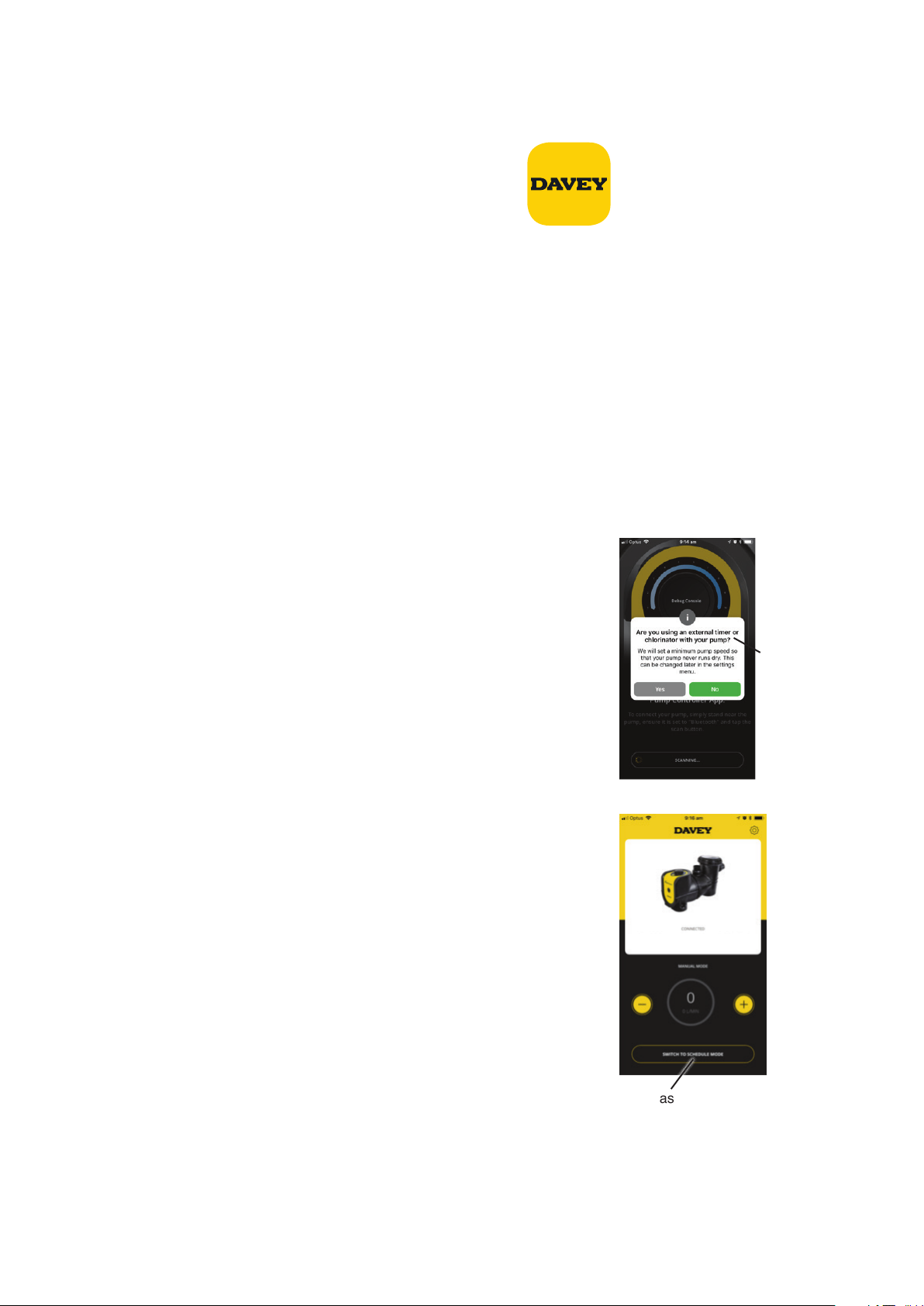
6. FUNZIONALITÀ BLUETOOTH
Impostazione della app Bluetooth
• Aprire l'app "App Store" disponibile sul dispositivo
• Cercare "pompa per piscina Davey"
• Installare l'app sul dispositivo
L'app può essere installata su tutti i dispositivi desiderati, tuttavia, solo un dispositivo può controllare la
pompa in qualsiasi momento. La lingua e l'ora dell'app sono identiche alle impostazioni del dispositivo. Le
unità di misura sono automaticamente impostate su unità di regione del dispositivo, tuttavia è possibile
scegliere tra Litri, Galloni o m
Associazione di un dispositivo alla pompa
• Aprire l’app sul proprio dispositivo smart
• Ruotando il selettore della pompa da "off" a "Bluetooth", il LED lampeggerà in bianco per un secondo
• Sul dispositivo, premere il tasto di connessione
• Quando si imposta SOLO per la prima volta, selezionare "SÌ" per consentire la localizzazione
• Si prega di notare che la prima volta che i dispositivi sono accoppiati, vi è un limite di tempo di 2 minuti per
farlo dopo di che la procedura dovrà essere ripetuta
Timer esterno/Cloratore
Apparirà un pop-up che chiede se si sta utilizzando un timer esterno o un
cloratore per controllare la pompa SilensorPRO. Selezionare "SÌ" o "NO".
Questa è una funzione di sicurezza che aiuta a garantire il funzionamento
del cloratore solo con la pompa in funzione.
3
/h.
Nota: le screenshot dell’app servono esclusivamente a scopo dimostrativo.
Le schermate effettive possono variare.
Apparirà questo
pop-up
Modalità manuale o di programmazione
Sono disponibili due modalità, a seconda se si desidera utilizzare la
pompa SilensorPRO manualmente o in alternativa è possibile creare un
programma di funzionamento.
Modalità manuale
• Se in modalità di programmazione, premere "passa alla modalità
manuale"
• L'app sarà ora in modalità manuale e potrete regolare manualmente la
velocità premendo i pulsanti (+/-)
• In modalità manuale, la pompa SilensorPRO funzionerà alla velocità
impostata, anche se il telefono non è nel raggio d'azione
• Ogni volta che il selettore viene impostato sulla posizione Bluetooth,
funzionerà alla velocità impostata precedente dopo il ciclo di
adescamento
Modalità di programmazione
• Ci sono due opzioni (impostare un ciclo giornaliero o un ciclo
settimanale) premendo la casella desiderata
• Questa opzione consente di creare un "programma giornaliero” standard che gestirà costantemente i livelli
impostati ogni giorno.
SilensorPro BT
Per passare dalla modalità manuale a quella
di programmazione,
potete premere questo
pulsante.
51
Italiano
Page 52

Ci sono due opzioni (impostare un ciclo giornaliero o un ciclo
settimanale) premendo la casella desiderata. Questa opzione
consente di creare un "programma giornaliero” standard che
gestirà costantemente i livelli impostati ogni giorno
• L'opzione "ciclo settimanale" può essere impostata per l'intera
settimana, dandovi la possibilità di modificare i cicli della pompa
giornalieri a seconda del tempo, del carico del bagnante ecc.
Impostazione di un programma
SilensorPro BT
• Selezionare la casella relativa all'ora in cui si vuole che la pompa
funzioni
• Seleziona l'impostazione della velocità in cui si desidera che
la pompa funzioni in qualsiasi momento. Nota: Le impostazioni
della pompa (1-10) si riferiscono alla velocità di funzionamento
dalla più lenta e alla più veloce della pompa.
• Una volta che soddisfatti del programma, selezionare "Salva".
Le comunicazioni tra il dispositivo e la pompa possono
richiedere fino a 20 secondi, a seconda del programma
selezionato
• La riga nella parte inferiore dello schermo indica un riepilogo
su dov'è il programma per giorno e per ora. Questa schermata
riassuntiva può essere facilmente modificata facendo scorrere
verso l'alto o verso il basso le colonne sopra
• Nota: se si utilizza un cloratore, è necessario assicurarsi che
i tempi di “accensione” della pompa corrispondano ai tempi
di “accensione” del cloratore. La pompa rimarrà nell'ultima
modalità utilizzata, indipendentemente dalla modalità manuale
o di programmazione.
Impostazioni
Per modificare le impostazioni di configurazione, fare clic sull'icona delle impostazioni:
Selezionare per
modicare le impostazioni di programmazione
Selezionare se si
desidera il ciclo
giornaliero o il ciclo settimanale.
questo mostrerà le seguenti schermate (scorrere verso il basso nella schermata per informazioni complete).
Velocità di adescamento/velocità massima
Ogni volta che la pompa si avvia, passerà attraverso 2 minuti di adescamento per garantire che ci sia
l'acqua nel sistema. È possibile regolare la velocità con cui esegue questa operazione tra 5 e 10. La velocità
impostata limiterà la velocità massima della pompa in modalità manuale o di programmazione.
Italiano
52
Page 53

Controlavaggio
Può essere impostato come singola velocità o in alternativa impostare due velocità e la velocità della pompa
"passerà" tra le due impostazioni. La velocità minima può essere impostata tra 1-10, la velocità massima può
essere impostata solo tra 5-10.
Timer esterno presente
Accenderlo e spegnerlo, a seconda che si stia utilizzando un timer esterno / un cloratore.
Funzione di disconnessione
La funzione "disconnessione dalla pompa" può essere utilizzata per:
• Consentire a un altro dispositivo di controllare la pompa
• Disconnettersi in modo da non collegarsi automaticamente alla pompa
• Si prega di notare che la connessione Bluetooth si disconnetterà automaticamente dopo un minuto di
non comunicazione
Ripristino alle impostazioni di fabbrica
Ciò ripristinerà la pompa alle configurazioni di fabbrica e consentirà di avviare
nuovamente la procedura di configurazione.
• Selezionare "Ripristina pompa"
• Ruotare il selettore verso "off", quindi ruotare il selettore su "Bluetooth"
• È quindi possibile eseguire il riaccoppiamento con il telefono Questa procedura è
presente in modo che la pompa non possa essere ripristinata accidentalmente.
SilensorPro BT
Ricerca guasti della pompa
Nel caso in cui ci sia un guasto, apparirà la seguente schermata, con la
descrizione del testo sotto il guasto che indica come porvi rimedio.
Titolo del guasto Descrizione del guasto
Controllare che il motore possa ruotare
liberamente. Scollegare per 1 minuto e
Guasto della pompa - sovracorrente
Guasto alla pompa - sottotensione
Guasto della pompa - sovratemperatura
Guasto della pompa - motore in stallo
Guasto della pompa - sottocarico/mancanza
di adescamento
ricollegare per ripristinare. Se il problema
persiste, contattare Davey o un agente di
riparazione autorizzato.
Problema alla tensione di alimentazione Se la
corrente torna alla normalità, scollegare la spina
per 1 minuto e ricollegarla per ripristinare.
La pompa si è surriscaldata. Controllare la
temperatura ambiente. Impostare la velocità
minima possibile se la temperatura ambiente è
troppo elevata.
Controllare che il motore possa ruotare
liberamente. Scollegare per 1 minuto e
ricollegare per ripristinare.
Controllare la presenza di sufficiente acqua
all'interno della pompa. Scollegare per 1 minuto
e ricollegare per ripristinare. Se il problema
persiste, contattare Davey o un agente di
riparazione autorizzato.
53
Italiano
Page 54
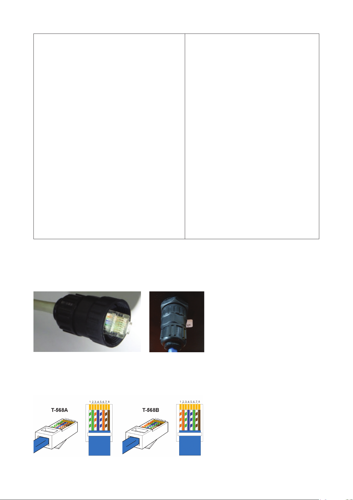
Guasto della pompa - sovratemperatura del motore; o
Guasto alla pompa - sovratensione; o
Guasto alla pompa - guasto messa a terra; o
Guasto alla pompa - guasto del sistema; o
Guasto alla pompa - guasto fase di uscita; o
Guasto alla pompa - sovraccarico alimentazione; o
Guasto alla pompa - checksum EEPROM; o
Guasto alla pompa - errore watchdog; o
Guasto alla pompa - protezione posteriore EFM; o
Guasto alla pompa - guasto del termistore; o
Guasto alla pompa - coppia sicura disattivata; o
Guasto alla pompa - comunicazione bus interna; o
Guasto alla pompa - errore applicazione; o
Guasto alla pompa - temperatura IGBT elevata; o
Guasto alla pompa - guasto ingresso analogico 4 mA; o
Guasto alla pompa - guasto esterno; o
Guasto alla pompa - errore di comunicazione del
tastierino; o
Guasto alla pompa - errore di comunicazione bus di
campo; o
Guasto alla pompa - errore interfaccia bus di campo.
Scollegare per 1 minuto e ricollegare per
ripristinare. Se il problema persiste, contattare
Davey o un agente di riparazione autorizzato.
7. IMPOSTAZIONI AVANZATE DELLA POMPA SP400BT
Panoramica della connessione AUX esterna
La pompa SilensorPRO SP400BT dispone di una presa impermeabile del tipo RJ45 per consentire il
controllo esterno della velocità del motore e altre funzionalità. È possibile utilizzare un cavo di rete RJ45
standard (senza avvio).
Figura 1: Spina RJ45 installata nell'alloggiamento (vista da dietro)
Si consiglia di mantenere la lunghezza del cavo la più corta possibile tra la pompa e il controller esterno o il
riscaldatore della piscina. Ci sono due principali configurazioni dei pin come mostrato di seguito:
PIEDINATURA RJ45
54
Italiano
Page 55

Figura 2: Connessioni pin RJ45
Pin Funzione T-568A T-568B
1 RS485 +ve Verde/Bianco Arancione/Bianco
2 RS485 -ve Verde Arancione
3 Ingresso digitale 3 Arancione/Bianco Verde/Bianco
4 Ingresso analogico Blu Blu
5 Terra 0 V CC Blu/Bianco Blu/Bianco
6 Ingresso digitale 2 Arancione Verde
7 Ingresso digitale 1 Marrone/Bianco Marrone/Bianco
8 24V Marrone Marrone
Verificare che il cavo utilizzato abbia i pin di codifica a colori di cui sopra da 1 fino a 8. Se è stata utilizzata
una codifica a colori alternativa, assicurarsi di registrare il colore corrispondente a ciascun pin per evitare
errori di connessione al controller o al riscaldatore della piscina. Se si utilizza un cavo alternativo, assicurarsi
che l'ingresso analogico e la terra siano un doppino.
La connessione 24 V deve essere utilizzata solo come riferimento per gli ingressi digitali - NON alimentare
apparecchiature esterne da questa guida di alimentazione.
Ingressi di controllo digitale
I 3 ingressi digitali consentono di ignorare l'impostazione della velocità di selezione. Per impostare uno di
questi ingressi:
• Collegare un'alimentazione 24 V isolata tra la terra CC e il pin di ingresso digitale
• Collegare i contatti commutabili di un relè tra il pin 24 V e l'ingresso digitale
Le velocità fisse (come percentuale della piena velocità) sono:
Ingresso 1 (Pin 7) Ingresso 2 (Pin 6) Ingresso 3 (Pin 3) Velocità di uscita
0 0 0 Selettore
0 0 24V 33%
0 24V 0 50%
0 24V 24V Controlavaggio
24V 0 0 100%
24V 0 24V 67%
24V 24V 0 83%
Interfacciamento dell'apparecchiatura con SilensorPRO SP400BT
AVVERTENZA! Per eseguire il lavoro illustrato di seguito è necessario un elettricista
qualicato.
La pompa SilensorPRO SP400BT può essere controllata da altre apparecchiature per accenderla ad alta
velocità (o qualsiasi altra velocità preimpostata, vedere la sezione 8 per i dettagli). Questo al fine di ottenere
la massima efficienza, ad esempio quando si utilizza un riscaldatore a gas o una pompa di calore. Se
l'apparecchiatura ha un'uscita di segnale 18-24 V CC isolata, collegare semplicemente il pin 7 a 24 V CC
positivo e il pin 5 alla terra CC come illustrato nello schema seguente:
Controlling Equipment
Pin7 (Brown/White)
To RJ45 Socket of VSD Pump
Pin5 (Blue/White)
+ 18 ~ 24V DC
DC Ground
Italiano
55
Page 56
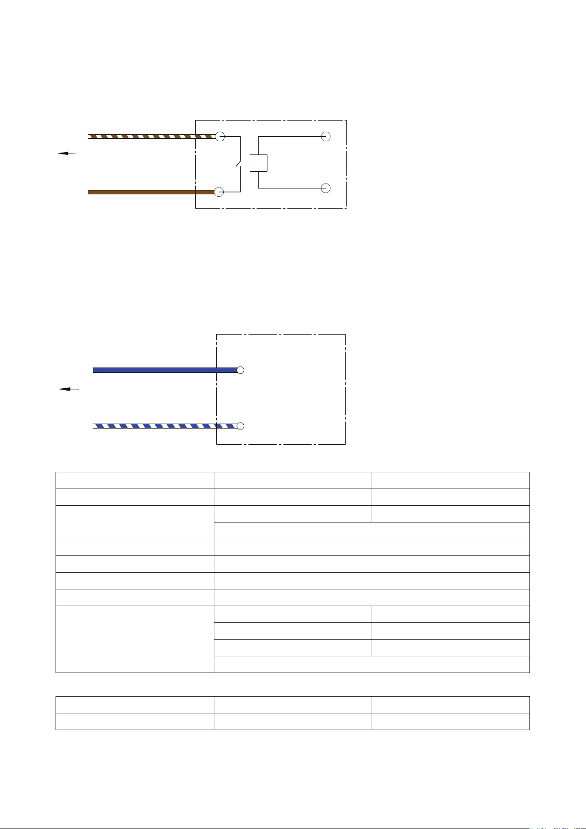
Se l'apparecchiatura di controllo non ha un'uscita di tensione di 18-24 V CC come sopra, ma dispone di
un'uscita di segnale a 24 V CA, 230 V CA, 12 CA o 12 CC, un relè adeguato (la tensione della bobina deve
essere uguale alla tensione di uscita del segnale dell'apparecchiatura di controllo) può essere impiegato a
tale scopo come menzionato sopra, e mostrato nel seguente schema:
Controlling Equipment
Pin7 (Brown/White)
To RJ45 Socket of VSD Pump
Pin8 (Brown)
Relay (Dry)
Contact
Relay Coil, must be
the same voltage
as the equipment
signal output
Se l'apparecchiatura di controllo ha già l'uscita relè (contatto secco) per il controllo, non è necessario un relè
aggiuntivo, basta collegare il pin 7 (marrone/bianco) e il pin 8 (marrone) ai contatti secchi come mostrato
nella parte sinistra dello schema di sopra.
Ingressi di controllo analogico
Il controllo della velocità può essere ottenuto anche collegando un segnale 0-10 V CC all'ingresso sul pin
4 (massa in corrispondenza del pin 5). Non appena viene registrato un segnale superiore a 0V, questo
ingresso avrà la priorità sulle impostazioni di selezione. Ad esempio, un segnale da 10 V CC cambierà la
velocità della pompa al 100%, mentre un segnale da 5 V CC cambierà la velocità della pompa al 50% ecc.
Controlling Equipment
+ 0~ 10 V DC Signal Output
Pin4 (Blue)
To RJ45 Socket of VSD Pump
Pin5 (Blue/White)
of controlling equipment
DC Ground
8. SPECIFICHE TECNICHE
Modello
Testa max (m)
GIRI/MIN
Classe involucro (IP)
Classe di isolamento
Tensione (V)
Frequenza di alimentazione (Hz)
Potenza in ingresso motore: (W)
Limiti di funzionamento
Temperatura max acqua:
Temperatura ambiente max:
SP200BT SP400BT
20 26
Velocità 1 – 10: 1500 – 3600 Velocità 1 – 10: 1.050 – 3.100
Velocità di controlavaggio: variabile
45
F
220 – 240VAC
50/60 Hz
Velocità 1: 128 Velocità 1: 126
Velocità 5: 524 Velocità 5: 728
Velocità 10: 1.111 Velocità 10: 1.639
Velocità di controlavaggio: variabile
40°C 40°C
50°C 50°C
56
Italiano
Page 57

Dimensioni
C
B
D
A
E
A
305mm 670mm 320mm 350mm 65mm 230mm 380mm 200mm 250mm 10mm 50/63 14
9.
USARE LA POMPA SILENSORPRO CON UN CLORATORE DI ACQUA SALATA
B C
D E F G H I
G
F
H
I
Diametro fori
di montaggio
Ingresso/
Uscita
PVC
Peso
netto
(kg)
I cloratori richiedono una portata minima attraverso la cella del cloratore per la massima efficienza e durata
della cella. Consultare la guida del proprio cloratore come riferimento per la portata richiesta dal proprio
sistema per piscina. Assicurarsi che la portata sia sufficiente per coprire completamente le piastre della cella
del cloratore in ogni momento del funzionamento.
10. FUNZIONAMENTO DEL PULITORE PER PISCINE AD ASPIRAZIONE
Prima di installare o acquistare un pulitore per piscine da utilizzare con la pompa SilensorPRO, è importante
conoscere le portate minime richieste per un funzionamento efficace.
Per il funzionamento di un pulitore per piscine ad aspirazione:
• Attivare l'impostazione Flusso Alto (10) e consentire alla pompa di adescarsi al massimo facendola
funzionare per circa 2 minuti. Vi accorgerete che la pompa è adescata quando è possibile vedere un forte
flusso d'acqua attraverso il coperchio trasparente del cestello delle foglie
• Quando tutta l'aria viene espulsa dal cestello delle foglie, collegare saldamente il tubo del pulitore della
piscina alla piastra del separatore o all'aspirazione a parete dedicata
• Selezionare l'impostazione della velocità che consente di ottenere le migliori prestazioni dal pulitore per
piscina di aspirazione. La velocità da 3 a 7 dovrebbe essere sufficiente per la maggior parte dei pulitori,
tuttavia se il pulitore richiede prestazioni migliori, selezionare la velocità da 7 a 10
• Il pulitore deve essere collegato solo per il tempo necessario a pulire la superficie della piscina. Al termine
della pulizia, scollegare il pulitore e rimuovere la piastra del separatore dalla scatola del separatore
• Riattivare la velocità più efficiente per la filtrazione giornaliera. Si consiglia la velocità da 1 a 4
NOTA: Per ottenere l'efcienza energetica ottimale dal SilensorPRO, NON tenere
collegato il pulitore della piscina di aspirazione quando non è necessaria la pulizia.
NOTA: Se la pompa SilensorPRO è collegata a un orologio in tempo reale o ad un altro
controllo automatico, il cablaggio deve essere rimosso da un tecnico qualicato.
• Chiudere le valvole dell'acqua sul tubo di ritorno della piscina e le tubazioni di ingresso della pompa SilensorPRO
• Rimuovere le valvole a sfera di scarico e di aspirazione facendo attenzione di non perdere gli o-ring
• Spostare le tubazioni con le valvole a sfera attaccate fino a quando la pompa SilensorPRO possa essere
tirata in modo libero
NOTA: Quando si inviano richieste relative alla pompa SilensorPRO, assicurarsi di
citare il numero del modello riportato sulla targhetta situata sul motore.
Italiano
57
Page 58

11. RISOLUZIONE DEI PROBLEMI
Se la pompa funziona ma non c'è flusso d'acqua o il flusso dell'acqua è ridotto, si può verificare la
seguente condizione:
• Il filtro richiede il controlavaggio o è ostruito. Fare riferimento alla sezione pertinente nel manuale del filtro
• La pompa non è adescata. Ri-adescarla come da istruzioni in 'Avvio della pompa'
• Sono presenti perdite d'aria nelle tubazioni di aspirazione. Controllare tutte le tubazioni ed eliminare le
perdite, controllare anche se il coperchio del cestello del filtro è allentato. Le bolle d'aria nell'acqua che
scorre verso la piscina indicherebbero una perdita nell'aspirazione verso la pompa permettendo all'aria di
entrare nelle tubazioni
• Una guarnizione dell'albero della pompa che perde potrebbe anche impedirne il funzionamento.
Un'ulteriore prova di ciò può essere la presenza di acqua a terra sotto la pompa
• La pompa non è in grado di prelevare acqua dalla piscina. Verificare che le valvole della pompa siano
completamente aperte e che il livello dell'acqua della piscina sia all'altezza della scatola del separatore.
Solitamente, è sufficiente che la scatola del separatore sporga per metà
• Ostruzione nelle tubazioni o nella pompa. Rimuovere il cestello del filtro e verificare la presenza di
eventuali ostruzioni all'ingresso della girante della pompa. Controllare che la scatola del separatore non sia
ostruita
Se la pompa non funziona, si possono verificare le seguenti condizioni:
• L'alimentazione non è collegata. Solo per 220-240 volt, controllare il punto di alimentazione collegando
un apparecchio portatile per assicurarsi che l'alimentazione sia disponibile. Controllare anche i fusibili e
l'interruttore di alimentazione principale
• Il sovraccarico automatico è scattato. La pompa ha un sovraccarico termico incorporato che si ripristina
automaticamente dopo che il motore si è raffreddato dopo un periodo di surriscaldamento. Determinare la causa
dell'intervento di sovraccarico e correggere. Ripristinare la pompa spegnendo l'alimentazione per 30 secondi
• L'ostruzione impedisce alla pompa di ruotare
12. RIMOZIONE DELLA POMPA SILENSORPRO DALLE TUBAZIONI
Se fosse necessario rimuovere la pompa SilensorPRO, seguire le seguenti istruzioni:
• Spegnere l'alimentazione e rimuovere la spina dalla fonte di alimentazione
• Svitare il raccordo nella parte anteriore e superiore della pompa, sganciando la pompa dalle tubazioni
• Far scivolare la pompa fuori posizione
13. QUALITÀ DELL'ACQUA
CHIMICA CONSIGLIATA DELL’ACQUA DELLA PISCINA
BILANCIAMENTO
DELL’ACQUA DELLA
PISCINA
Lettura/intervallo
ideale
Per aumentare
Per diminuire
Cloro libero
(ppm)
1 – 3
Aumentare
la potenza
del cloratore.
Aggiungere cloro.
Aumentare il tempo
di ltrazione.
pH
Piscine
piastrellate e in
calcestruzzo:
7,4-7,6
Altre superci:
7,2-7,4
Aggiungi
carbonato di
sodio
Aggiungere
acido muriatico
Alcalinità totale
TA
(ppm)
Piscine piastrellate
e in calcestruzzo –
80-120.
Altre superci –
125-150
Aggiungere
bicarbonato di
sodio
Aggiungere acido
muriatico
o acido secco
Durezza del calcio
(ppm)
Piscine piastrellate
e in calcestruzzo –
200-275.
Altre superci –
100-225
Aggiungere cloruro
di calcio
Svuotare
parzialmente e
riempire nuovamente
la piscina con acqua
di durezza inferiore
per diluire
Stabilizzante
- acido
cianurico
(ppm)
25 – 50 4500 – 6000
Aggiungere
acido
cianurico
Svuotare
parzialmente
e riempire
nuovamente
la piscina per
diluire
Livello salino
ottimale
(ppm)
Aggiungi sale
Svuotare
parzialmente
e riempire
nuovamente la
piscina
per diluire
Frequenza del test Ogni settimana Ogni settimana Ogni settimana Ogni settimana Regolarmente Regolarmente
Italiano
58
Page 59

Attività di manutenzione ordinaria - per massimizzare la durata delle apparecchiature
della piscina e la sicurezza personale, utilizzare questa lista di controllo una volta alla
settimana. Spegnere dapprima la pompa.
a. Assicurarsi che tutti i manometri siano funzionanti e che la pressione operativa sia
entro i limiti specicati sul prodotto.
b. Assicurarsi che ciascun ingresso di aspirazione e lo scarico principale siano dotati di
un coperchio saldamente ssato e in condizioni di funzionamento sicuro.
c. Assicurarsi che tutti i coperchi del separatore siano ssati saldamente e in condizioni
di funzionamento sicuro. Questi dovrebbero essere sostituiti ogni 3 o 4 anni.
d. Rimuovere eventuali ostruzioni o detriti dal coperchio dello scarico principale.
e. Accertarsi che i cestelli del separatore e i ltri dei capelli e lanugine della pompa
siano privi di foglie e detriti almeno una volta alla settimana.
f. Rimuovere ostruzioni e combustibili attorno al motore della pompa.
g. Assicurarsi che tutti i collegamenti dei cablaggi siano puliti e che tutti i cablaggi e le
apparecchiature elettriche siano in buone condizioni. Il cablaggio danneggiato deve essere
riparato o sostituito da un elettricista qualicato non appena viene rilevato un danno.
h. Controllare i livelli di equilibrio idrico e dell’igienizzante presso il proprio punto di
vendita locale.
I COLLEGAMENTI ELETTRICI E I CABLAGGI DEVONO ESSERE EFFETTUATI DA UN
ELETTRICISTA AUTORIZZATO.
PERICOLO Aspirazione pericolosa. Non bloccare l'ingresso di acqua nel sistema di
ltrazione con nessuna parte del corpo in quanto la pressione può intrappolare i capelli o
parti del corpo, causando lesioni gravi o morte. Non bloccare l'aspirazione.
Spegnere immediatamente la pompa se qualcuno rimane intrappolato.
Non utilizzare o far funzionare piscine, spa o bagni termali se un coperchio di aspirazione
è rotto, mancante o allentato. Per evitare l'intrappolamento per effetto dell’aspirazione,
devono essere previsti due coperchi di aspirazione e ingressi in ogni pompa.
Conformemente alla norma AS/NZS60335.2.41 siamo tenuti a informarvi che questo
dispositivo non deve essere usato da bambini o persone inferme e non deve essere
usato come un giocattolo dai bambini.
ATTENZIONE! Non aggiungere prodotti chimici direttamente al separatore della piscina.
L'aggiunta di sostanze chimiche non diluite può danneggiare la pompa e il ltro e
invalidare la garanzia.
59
Italiano
Page 60

Garanzia Davey
Davey Water Products fornisce garanzie che non possono essere escluse dalla legge locale. Avete diritto
a una sostituzione o al rimborso in caso di guasto grave e al risarcimento di qualsiasi altra perdita o danno
ragionevolmente prevedibile. Avete inoltre diritto a far riparare o sostituire il prodotto qualora non fosse di qualità
accettabile e il guasto non costituisse un guasto grave.
Davey Water Products Pty Ltd (Davey) con sede a 6 Lakeview Drive Scoresby VIC 3179 fornisce la seguente
garanzia in relazione a questo prodotto. Fatte salve le esclusioni e le limitazioni di seguito, Davey assicura che il
prodotto sia privo di difetti di materiale e lavorazione per un periodo di 24 mesi dalla data di acquisto (periodo di
garanzia).
In presenza di un difetto nel prodotto prima del termine del periodo di garanzia, e qualora Davey ritenesse il prodotto
difettoso per quanto riguarda i materiali o la lavorazione, a sua esclusiva discrezione Davey potrà:
1. sostituire o riparare gratuitamente il prodotto o la parte difettosa del prodotto; o
2. disporre la riparazione o la sostituzione del prodotto o della parte difettosa da parte di un riparatore qualificato,
a titolo gratuito.
Davey si riserva il diritto di sostituire parti difettose del prodotto con parti o componenti di qualità, grado e
composizione simili qualora non fossero disponibili parti o componenti identici. I prodotti presentati per la
riparazione possono essere sostituiti da prodotti ricondizionati dello stesso tipo piuttosto che essere riparati.
Richieste in garanzia:
1. In caso di guasto coperto dalla garanzia, Davey suggerisce, in prima istanza, di contattare il rivenditore Davey
dal quale è stato acquistato il prodotto. In alternativa, è possibile: telefonare alla linea di assistenza clienti Davey
al numero 1300 367 866 in Australia o 0800 654 333 in Nuova Zelanda; inviare una lettera scritta all'indirizzo
Davey sopra elencato; oppure inviare un’e-mail all’indirizzo sales@davey.com.au.
2. Qualsiasi reclamo in garanzia deve essere accompagnato dalla prova di acquisto e dai dettagli del presunto
difetto.
3. Alla ricezione del reclamo, Davey cercherà di risolvere il problema e, se il prodotto è difettoso o malfunzionante,
consiglierà come procedere per la riparazione, ottenere una sostituzione o un rimborso.
4. Questa garanzia è limitata ai difetti dei materiali o di lavorazione del prodotto e non copre le parti soggette a
consumo o la sostituzione di parti a seguito di usura e rottura.
Esclusioni:
La garanzia non si applica nei casi in cui:
1.
Il Prodotto sia stato modificato, riparato o sottoposto a manutenzione da una persona diversa da Davey o da un
riparatore autorizzato.
2. Davey non sia in grado di riscontrare alcun difetto nel prodotto dopo il collaudo.
3. Il prodotto sia stato utilizzato per finalità diverse da quelle per cui è stato progettato.
4. Il prodotto sia stato esposto a condizioni anomale, sia in termini di temperatura, acqua, umidità, pressione,
sollecitazioni o simili.
5. L'acquirente abbia utilizzato o montato parti e accessori non originali o non approvati.
6. Il difetto del Prodotto sia sorto a seguito di abuso, uso improprio, negligenza o incidente.
7. Il difetto del Prodotto sia sorto a seguito di una conservazione o un utilizzo del Prodotto non corretti da parte
dell'acquirente.
8. Il danno sia stato causato dall'uso di prodotti chimici e detergenti non approvati da Davey.
Se il prodotto Davey richiede riparazioni o manutenzione una volta decorso il periodo di garanzia, contattare il
rivenditore Davey più vicino, oppure telefonare o inviare un'e-mail al centro di assistenza clienti Davey. Per un elenco
completo dei rivenditori Davey, visitare il nostro sito Web.
ESTERO
Uffi cio principal
Ph: +613 9730 9124
Fax: +613 9753 4248
Email: export@davey.com.au
Davey Water Products Pty Ltd
Member of the GUD Group
ABN 18 066 327 517
AUSTRALIA
Uffi cio principale
6 Lakeview Drive,
Scoresby, Australia 3179
Ph: 1300 232 839
Fax: 1300 369 119
Email: sales@davey.com.au
Website: davey.com.au
® Davey is a trademark of Davey Water Products Pty Ltd. © Davey Water Products Pty Ltd 2019.
Website: davey.com.au
EUROPA
ZAC des Gaulnes
355 Avenue Henri Schneider
69330 Meyzieu, France
Ph: +33 (0) 4 72 13 95 07
Fax: +33 (0) 4 72 33 64 57
Email: info@daveyeurope.eu
Website: daveyeurope.eu
NUOVA ZELANDA
7 Rockridge Avenue,
Penrose, Auckland 1061
Ph: 0800 654 333
Fax: 0800 654 334
Email: sales@dwp.co.nz
Website: daveynz.co.nz
NORD AMERICA
Ph: +1 866 328 7867
Email: export@davey.com.au
Website: daveyusa.com
MEDIO ORIENTE
Ph: +971 50 6368764
Fax: +971 6 5730472
Email: info@daveyuae.com
Website: daveyuae.com
60
P/N 403308-1
Page 61

SilensorPRO SP200BT & SP400BT
Zwembadpomp
Installatie- en gebruiksinstructies
50/60Hz
SP200BT
Kijk op de Davey website in uw regio zoals vermeld op de achterkant van
dit document voor updates van de productinformatie.
Geef deze instructies aan de persoon die met de uitrusting werkt.
SP400BT
Nederlands
Page 62

Gefeliciteerd met de aankoop van een uw kwaliteitsproduct, SilensorPro SP200BT of SilensorPro SP400BT
pom. Alle productelementen zijn ontworpen en vervaardigd voor probleemloze, betrouwbare werking.
Inhoudsopgave:
1. INSTALLATIE VAN DE DAVEY POMPP MET VARIABELE SNELHEID
Elektrische aansluitingen ..........................................................................................................................63
Aansluiting van de slangen .......................................................................................................................64
2. TYPISCH INSTALLATIESCHEMA ............................................................................................................65
3. PRESTATIESPECIFICATIES ....................................................................................................................65
3.1 SP200BT hydraulische prestatie .........................................................................................................65
3.2 SP200BT elektrische specificaties ......................................................................................................66
3.3 SP400BT hydraulische prestatie .........................................................................................................66
3.4 SP400BT elektrische specificaties ......................................................................................................66
4. GEBRUIKSHANDLEIDING .......................................................................................................................67
Energie besparen met uw SilensorPRO ...................................................................................................67
Pre-start-up checklist ................................................................................................................................67
Lage energiewerking ................................................................................................................................68
Richtlijnen voor aanbevolen pompwerkingsuren ......................................................................................68
Legen van het zeefmandje .......................................................................................................................69
Routine-onderhoud ...................................................................................................................................69
5. KENMERKEN & FUNCTIES ....................................................................................................................70
Meerkleurige led verklikkerlampje ............................................................................................................70
Backwash Speed Cycling Technology ......................................................................................................70
Volledig variabele frequentieaandrijving met gebruiksvriendelijke snelheidskeuze ..................................70
Grote 4,5 liter pompmand .........................................................................................................................70
Gepatenteerd water gekoeld design voor vlotte en stille werking .............................................................70
SP400BT constante flow/snelheidscompensatie ......................................................................................70
SP400BT weerbestendige RJ45 communicatiepoort (zie pagina 7 voor aansluitingsinformatie) .............70
6. BLUETOOTH FUNCTIE ...........................................................................................................................71
Bluetooth app set-up .................................................................................................................................71
Koppelen van een apparaat aan de pomp ................................................................................................71
Externe timer/chlorinator ...........................................................................................................................71
Geprogrammeerde modus ........................................................................................................................71
Instellen van een programma ...................................................................................................................72
Instellingen ................................................................................................................................................72
Priming snelheid/Max snelheid .................................................................................................................72
Backwash..................................................................................................................................................73
External Timer Present .............................................................................................................................73
Loskoppelen functie ..................................................................................................................................73
“Factory Reset” (reset fabrieksinstellingen) ..............................................................................................73
Pomp defecten zoeken .............................................................................................................................73
7. GEAVANCEERDE SETUP VAN DE SP400BT .........................................................................................74
Externe AUX aansluitingen overzicht ........................................................................................................74
Digitale controle input ...............................................................................................................................75
Interfacing uitrusting bij de SilensorPRO SP400BT ..................................................................................75
Analoge controle input ..............................................................................................................................76
8. TECHNISCHE SPECIFICATIES ...............................................................................................................76
9. GEBRUIK VAN UW SILENSORPRO MET ZOUT WATER CHLOREERDER ..........................................77
10. GEBRUIK VAN UW ZUIGREINIGER VOOR ZWEMBAD .........................................................................77
11. PROBLEEMOPLOSSING: ........................................................................................................................78
12. DE POMP VAN DE SLANGEN AFKOPPELEN ........................................................................................78
13. WATERKWALITEIT...................................................................................................................................78
14. DAVEY GARANTIE ...................................................................................................................................80
62
Nederlands
Page 63

1. INSTALLATIE VAN DE DAVEY POMP MET VARIABELE SNELHEID
De SilensorPRO moet zo dicht mogelijk bij het water worden geplaatst en gemonteerd worden op een
stevige basis op een goed gedraineerde plaats die hoog genoeg is om overstroming te voorkomen. Het is de
verantwoordelijkheid van de installateur/eigenaar om de pomp zodanig te plaatsen dat het naamplaatje goed
leesbaar is en de SilensorPRO goed toegankelijk is voor onderhoud. Wij raden u aan de SilensorPRO tegen
weersomstandigheden te beschermen. Behuizingen of overkappingen moeten goed geventileerd worden om
condens te voorkomen.
Niet-naleving van deze instructies en alle toepasselijke codes kan ernstig lichamelijk
letsel en/of materiële schade veroorzaken.
Deze pomp vereist professionele kennis van installatie en onderhoud. De installatie van
dit product moet daarom worden uitgevoerd door een persoon die ervaring heeft met de
loodgietersvereisten van zwembaden en die de instructies in deze handleiding correct volgt.
Elektrische aansluitingen
BELANGRIJKE INFORMATIE Uw SilensorPRO is dubbel geïsoleerd op het watercircuit.
Als een potentiaalvereffeningsstructuur is vereist, wordt een potentiaalvereffeningspunt
voorzien. (Zie uw plaatselijke wet- en/of regelgeving voor AS/NZ/3000 equivalente
bedradingsnormen).
LET OP! Uit veiligheidsoverwegingen adviseren wij alle merken en types zwembadpompen
te (laten) installeren conform AS/NZS 3000 richtlijn of volgens plaatselijke regelgeving
inzake bedrading of equivalente normen. Alle elektrische installatiewerkzaamheden moeten
worden uitgevoerd door een gekwaliceerde elektricien. Davey raadt aan alle installaties
te voorzien van een aardlekschakelaar of residuele stroombeveiligingsvoorzieningen.
Nominale bedrijfsstroom mag niet meer zijn van 30mA.
WAARSCHUWING! Zorg dat er een elektrische isolatieschakelaar geplaatst wordt die
gemakkelijk toegankelijk is zodat de pomp in een noodgeval uitgeschakeld kan worden.
F NFC C 15-100 GB BS7671:1992
D DIN VDE 0100-702 EW EVHS-HD 384-7-702
A OVE 8001-4-702 H MSZ 2364-702:1994/MSZ 10-533 1/1990
E UNE 20460-7-702 1993, REBT ITC-BT-31 2002 M MSA HD 384-7-702.S2
IRL IS HD 384-7-702 PL PN-IEC 60364-7-702: 1999
I CEI 64-8/7 CZ CSN 33 2000 7-702
LUX 384-7.702 S2 SK STN 33 2000-7-702
NL NEN 1010-7.702 SLO SIST HD 384-7-702.S2
Davey SilensorPro is geschikt voor aansluiting op een nominale 240 - 240 volt 50/60Hz vermogensbron en is
voorzien van een flexkabel. Als er geen stopcontact aanwezig is binnen 3 meter van de pomp, kan een 3-pin
voedingspunt worden voorzien door een elektricien op een droge, veilige plaats. Verlengsnoeren zijn onveilig
rond zwembaden en moeten vermeden worden. Als het snoer van de SilensorPRO beschadigd is, moet het
vervangen worden door doro originele Davey-onderdelen door Davey of een erkende dealer.
Deze SilensorPro is voorzien van een motor overbelastingdetectie die ontworpen is om de motor te beschermen
tegen oververhitting. Als de motor te warm wordt tijdens werking, wordt de werkingssnelheid verminderd totdat
een acceptabele werkingstemperatuur is bereikt. Daarna wordt de ingestelde snelheid hersteld.
Om de motor te resetten, schakelt u het apparaat 30 seconden uit en vervolgens weer in via de hoofdschakelaar.
Nederlands
63
Page 64

Aansluiting van de slangen
Figure 1.2
152mm
MINIMUM
76mm
MINIMUM
Suction line
50/63mm
Return to
Pool
50/63mm
Return to
De pijpkoppelingen zijn bedoeld voor aansluiting van de slangen op het zwembad. De pompen zijn
ontworpen voor 50/63 mm pvc koppelingen.
BELANGRIJKE INFORMATIE Als de SilensorPRO Als en het lter zich onder het
zwembadwaterniveau bevinden, moeten isolerende kleppen geplaatst worden in de
slang tussen de pomp en de skimmer box en in de retourslang van het lter naar
het zwembad. Zorg er bij het aansluiten van de afvoerslang voor dat de slang de
snelheidskeuzeknop van de pomp niet hindert. De pijpkoppelingen moeten met de hand
vast gedraaid worden. Er is geen afsluitmiddel, lijm of siliconen nodig.
De koppelingen van de SilensorPRO zijn vervaardigd uit ABS. Bepaalde PCV
pakkingcomponenten zijn compatibel met ABS. Controleer vóór gebruik de
geschiktheid van de componenten.
Gebruik van slangen die kleiner zijn dan de hierboven vermelde formaten, wordt afgeraden. Afzuigslangen
mogen geen luchtlekken, bobbels en knikken bevatten die problemen bij het afzuigen kunnen veroorzaken.
Voor optimale efficiëntie moet de SilensorPRO zo geïnstalleerd worden dat turbulentie in het water zo veel
mogelijk wordt beperkt. Zoals weergegeven op afbeelding 1.1 moet u geen hoek van 90° installeren op
minder dan 250 mm van de koppeling. Als er isolatiekleppen worden gebruikt op uitrustingen onder het
waterniveau, moeten deze op minstens 250 mm van de inletkoppeling worden geïnstalleerd. Dit draagt bij
aan de laminaire stroming.
Figure 1.1
250mm
ELBOW
Suction line
50/63mm
Pool
50/63mm
De afvoerslang van de SilensorPRO outlet moet aangesloten worden op de inletaansluiting op het
zwembadfilter (normaal bij het filtercontroleventiel). Zoals weergegeven op afbeelding 1.2 moet er
voldoende ruimte zijn boven de pomp zodat het snelheidskeuzepaneel van de SilensorPRO goed te
bedienen is. Gebruik een terugslagventiel op de afvoerleiding als de pomp wordt gebruikt voor
toepassingen met aanzienlijk hoogteverschil naar de leidingen achter de pomp.
Figure 1.2
Return to
Pool
50/63mm
152mm
MINIMUM
Suction line
50/63mm
76mm
MINIMUM
Installeer altijd terugslagventielen als er gekoppeld wordt aan een andere pomp. Dit helpt reverse rotatie van
de propeller en de motor voorkomen.
WAARSCHUWING! Pompzuiging is gevaarlijk en kan leiden tot beknelling, verdrinking
of letsel aan de ingewanden van zwemmers. Blokkeer de afzuiging niet. Gebruik geen
zwembaden, spa's of spabaden als een zuigerafsluiting kapot, is, ontbreekt of los zit.
Er moeten bij elke pomp twee zuigerafsluitingen en ingangen verstrekt worden om
beknelling in de zuiger te voorkomen.
Nederlands
64
Page 65
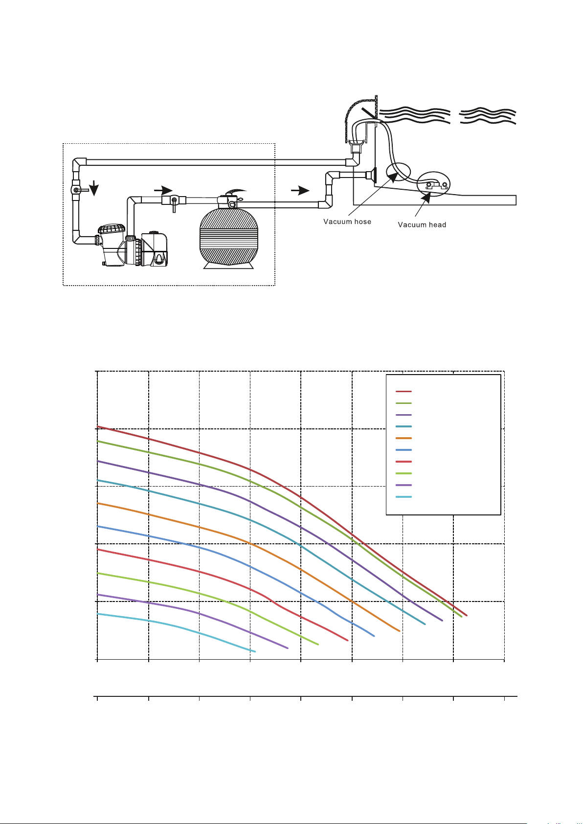
2. TYPISCH INSTALLATIESCHEMA
ProMaster - PM200SV
Performance
Pool pump Media Filter
3. PRESTATIESPECIFICATIES
3.1 SP200BT hydraulische prestatie
25
20
15
Total Head ( m )
10
5
Dial position No. 10
Dial position No. 9
Dial position No. 8
Dial position No. 7
Dial position No. 6
Dial position No. 5
Dial position No. 4
Dial position No. 3
Dial position No. 2
Dial position No. 1
0
0 50 100 150 200 250 300 350 400
Flow ( lpm )
0
036 9 12 15 18 21 24
3
Flow ( m
/h )
Nederlands
65
Page 66

3.2 SP200BT elektrische specificaties
450
Snelheid
Instelling
Kies 1 0,17 128 0,12 90
Kies 2 0,28 207 0,19 145
Kies 3 0,39 293 0,27 205
Kies 4 0,53 398 0,37 279
Kies 5 0,70 524 0,49 367
Kies 6 0,87 655 0,61 459
Kies 7 1,08 807 0,75 565
Kies 8 1,25 936 0,87 655
Kies 9 1,44 1.078 1,01 755
Kies 10 1,48 1.111 1,04 778
hp W hp W
Input Output
3.3 SP400BT hydraulische prestatie
25
Dial position No. 10
Dial position No. 9
Dial position No. 8
20
15
Dial position No. 7
Dial position No. 6
Dial position No. 5
Dial position No. 4
Dial position No. 3
Dial position No. 2
Dial position No. 1
Total Head ( m )
10
5
0
0 50 100 150 200 250 300 350 400
Flow ( lpm )
0
036 9 12 15 18 21 24 27
3
Flow ( m
/h )
3.4 SP400BT elektrische specificaties
Snelheid
Instelling
Kies 1 0,17 126 0,12 89
Kies 2 0,28 210 0,20 147
Kies 3 0,46 347 0,32 243
Kies 4 0,70 522 0,49 366
Kies 5 0,97 728 0,68 510
Kies 6 1,22 913 0,85 639
Kies 7 1,61 1.211 1,13 848
Kies 8 1,97 1.478 1,38 1.034
Kies 9 2,18 1.635 1,59 1.191
Kies 10 2,19 1.639 1,62 1.212
hp W hp W
Input Output
66
Nederlands
Page 67

4. GEBRUIKERSHANDLEIDING
Deze SilensorPRO is voorzien van Bluetooth, u kunt de pompfuncties dus instellen en bedienen vanaf uw
smart apparaat. Bluetooth is een draadloos communicatieprotocol dat communicatie tussen apparaten
mogelijk maakt. Deze functie wordt ondersteund door alle apparaten die een app kunnen downloaden van
iOS of Android App Store.
Lees deze instructies volledig voordat u de pomp inschakelt. Als u twijfelt over een deel van de installatieen gebruiksinstructies, kunt u contact opnemen met Davey via de informatie zoals vermeld wordt op de
achterkant van dit document.
Elke SilensorPro ondergaat een watertest op een aantal flow-, druk-, voltage-, stroom- en mechanische
prestatieparameters De geavanceerde pompvervaardigingstechnologie van Davey biedt een betrouwbare en
efficiënte pompprestatie met een lange levensduur.
Energie besparen met uw SilensorPRO
De Davey pomp met variabele snelheid is een uiterst efficiënte pomp die gebruik maakt van een vernuftige,
ultramoderne variabele AC motor die weinig lawaai maakt, weinig werkingskosten met zich meebrengt en
minder broeikasgassen uitstoot dan een traditionele pomp.
Omdat de pomp aan lagere snelheden dan een traditionele pomp kan draaien, slijt uw pomp mechanisch
ook minder snel aangezien de interne elementen minder zwaar worden belast. Energiebesparend pompen
is heel eenvoudig. Laat de filterpomp langer werken op een lage snelheid dan een conventionele vaste
pompsnelheid om uw zwembadwater "om te draaien" voor correcte filtering en hygiëne. Dit resulteert in een
lager energieverbruik en tot 70% lagere werkingskosten.
De SilensorPRO heeft instelbare snelheden dus u kunt de doorstroomsnelheid van het zwembad of
spawater variëren. De snelheid kan worden aangepast aan de zuigreiniger van het zwembad, het in-floor
reinigingssysteem en zwembadverwarming. Er kan een backwash instelling worden gekozen om een
mediafilter te backwashen.
Wat kunt u verwachten van SilensorPRO (energie efficiënte werking) in uw zwembad:
• Als uw SilensorPro pomp een traditionele AC motor pomp vervangt, moet u deze langer laten draaien dan
uw oude pomp die op een vaste snelheid draaide. Dit is NORMAAL en u bespaart energie als u de lagere
snelheidsinstelling gebruikt
• U zult ook zien dat de drukmeter op uw filter een veel lagere druk aangeeft dan u gewend bent. Dit is
ook NORMAAL De lagere systeemdruk is het resultaat van de lagere snelheid en flow rate die de pomp
produceert.
• Bij werking bij lagere snelheidsinstellingen zult u merken dat de pomp veel minder lawaai maakt. Dit is een
groot voordeel want u kunt uw pomp laten draaien tijdens daluren waardoor u kosten kunt besparen. En
uw buren zullen hier ook heel blij mee zijn.
Veel zwembadproducten zijn gebaseerd op minimale flow rates voor optimale werking en/of efficiëntie. Als u low
flow instellingen gebruikt op uw SilensorPro (bijv. snelheid van 1 tot 4), raadt Davey aan om de compatibiliteit van
de snelheid of minimale flow rate die vereist is voor bepaalde zwembaduitrustingen, te controleren.
• Zuigreiniger zwembad;
• Ozongeneratoren;
• Verwarmingssystemen;
• Zout water chloreringcellen;
• In de bodem ingebouwd zwembad reinigingssystemen;
Pre-start-up checklist
• De gekozen snelheidsinstelling is een instelling die compatibel is met andere zwembaduitrustingen;
• De pomp is in een veilige en droge omgeving geïnstalleerd;
• De pompbehuizing is voorzien van correcte drainering in geval van een lek;
• Alle transportpluggen zijn verwijderd;
• De slangen zijn correct afgedicht en ondersteund;
• De pomp heeft correct aangezogen;
• De stroomtoevoer is correct aangesloten;
• Alle stappen voor veilige werking zijn uitgevoerd;
• Het filter is aangesloten op een slang van 50/63mm;
• De (App) programmeerinstelling komt overeen met andere tijden in het systeem.
Nederlands
67
Page 68

Lage energiewerking
Uw SilensorPro SP200BT heeft snelheidsinstellingen van 1,500 tot 3,600rpm. Uw SilensorPro SP400BT
heeft snelheidsinstellingen van 1,050 tot 3,100rpm: Snelheid 1 is de laagste snelheid en snelheid 10 is de
snelste.
• Snelheid 1 is de laagste snelheid en biedt daarom de meeste energie-efficiëntie en besparing.
Werking
Backwashen van uw mediafilter
Zwembadfiltering
Gebruik zuigreiniger zwembad
Uw zwembad handmatig reinigen
Waterfunctie werking
Spa jet werking
In de bodem ingebouwd reinigingssystemen
Zonneverwarming zwembad
Aanbevolen snelheidsinstelling
Backwash snelheid
Snelheid 1 tot 4
Snelheid 5 tot 8
Snelheid 9 tot 10
Richtlijnen voor aanbevolen pompwerkingsuren
De minimale turnover rate van privézwembaden is in principe een enkele turnover van het volledige volume
van het zwembadwater binnen de dagelijkse werkingsperiode van de pomp. De onderstaande tabellen
geeft alleen een richtlijn voor de werkingstijden van uw pomp in filtermodus om de minimale turnover rate te
behalen:
SilensorPRO SP200BT
Omvang zwembad
Liters
Snelheid 1 Snelheid 5 Snelheid 10
Snelheidsinstelling (uren)
20.000 3,3 1,7 1,1
30.000 5,0 2,5 1,7
40.000 6,7 3,3 2,2
50.000 8,3 4,2 2,8
60.000 10,0 5,0 3,3
80.000 13,3 6,7 4,4
100.000 16,7 8,3 5,6
SilensorPRO SP400BT
Omvang zwembad
Liters
20.000 2,4 1,3 0,9
30.000 3,7 2,0 1,4
40.000 4,9 2,7 1,9
50.000 6,1 3,3 2,3
60.000 7,4 4,0 2,8
80.000 9,8 5,3 3,8
100.000 12,3 6,7 4,7
Snelheidsinstelling (uren)
Snelheid 1 Snelheid 5 Snelheid 10
68
Nederlands
Page 69

Conform EN 60335.1 zijn wij verplicht u te informeren over het feit dat dit apparaat kan
worden gebruikt door kinderen van 8 jaar en ouder en personen met beperkte fysieke,
sensorische of geestelijke capaciteiten of een gebrek aan ervaring en kennis als gebruik
onder toezicht plaatsvindt of als zij instructies over het gebruik van het apparaat
hebben ontvangen van een persoon die verantwoordelijk is voor hun veiligheid.
Kinderen moeten onder toezicht staan om te voorkomen dat ze met het apparaat spelen.
Legen van het zeefmandje
Het zeefmandje moet geregeld worden gecontroleerd via het transparante deksel en geleegd worden als er
veel vuil in zit. Volg hiervoor de onderstaande instructies.
• Schakel de pomp uit;
• Schroef het deksel van het zeefmandje tegen de klok in los en verwijder het;
• Verwijder het zeefmandje door het omhoog te trekken;
• Verwijder het afval uit het mandje. Indien nodig met water uitspoelen.
OPMERKING: Stoot NOOIT met de plastic mand op een harde ondergrond, dit kan de
mand beschadigen.
• Controleer het zeefmandje op scheuren en plaatst het terug in de pomp als het in goede staat verkeerd;
• Doe het klepje dicht en controleer of het goed op de rubberen o-ring zit. Met de hand stevig aandraaien is
voldoende. De o-ring en de draad kunnen gesmeerd worden met Hydra slip of equivalente producten.
Het niet regelmatig uitvoeren van onderhoud kan schade veroorzaken die niet wordt
gedekt door de garantie.
Routine-onderhoud
Voor een optimale levensduur van uw SilensorPRO en uw persoonlijke veiligheid, controleert u elke week
deze checklist. Zorg dat de pomp is uitgeschakeld voordat u begint:
• Zorg dat drukmeters goed werken en dat de werkingsdruk binnen de grenzen ligt zoals op het product
wordt gespecificeerd;
• Zorg dat elke afzuigingang en de hoofddrain een deksel hebben die veilig is bevestigd en goed werkt;
• Zorg dat alle skimmers voorzien zijn van deksels die goed zijn bevestigd en goed werken. Deze moeten
om de 3 tot 4 jaar worden vervangen;
• Verwijder verstoppingen of vuil uit het deksel van de hoofddrain;
• Controleer minstens een keer per week of het skimmermandje en de pompmand vrij zijn van
bladeren en afval;
• Verwijder obstructies en brandbaar materiaal rond de pompmotor;
• Zorg dat alle bedradingsaansluitingen schoon zijn en dat de bedrading en de elektrische uitrusting
in goede staat verkeren. Beschadigde draden moeten gerepareerd of vervangen worden door een
gekwalificeerde elektricien zodra de beschadiging wordt ontdekt.
• Controleer het waterevenwicht en de gehaltes aan desinfecterende middelen via uw plaatselijke
zwembad speciaalzaak.
69
Nederlands
Page 70

5. KENMERKEN & FUNCTIES
De SilensorPRO heeft verschillende werkingsfuncties. Deze worden hierna uitgelegd.
Meerkleurige led verklikkerlampjes
Dit wordt gebruikt ter identificatie van vereiste instellingen voor het programmeren van de tijd voor
topsnelheid (boost) cycli en waarschuwingen:
• Blijft groen branden = normale keuzewerking
• Knippert langzaam groen = backwash
• Knippert snel groen = AUX externe controle blijft branden
• Blijft wit branden = tijd voor backwash
• Knippert snel wit = fout gedetecteerd - reset pomp
• Knippert langzaam blauw = bediening via Bluetooth
• Blijft blauw branden = Bluetooth modus
Backwash speed cycling technology
In de backwash modus draait de SilensorPRO tussen de lage en de hoge snelheid om beweging van de
filtermedia te bevorderen voor een efficiëntere reiniging. Dit vermindert afvalwater tijdens het backwash
circulatieproces.
Volledig variabele frequentieaandrijving met gebruiksvriendelijke
snelheidskeuze
• Biedt gemakkelijke keuze van de gewenste filtersnelheid
• Geen ingewikkelde digitale drukknopcontrole
Grote 4,5 liter pompmand
• Voor langere intervallen tussen reiniging
Gepatenteerd water gekoeld design voor vlotte en stille werking
De SilensorPRO heeft een water gekoeld membraan en jacket rond de motor die de pomp koel houden
tijdens werking. Afvoerwarmte van de motor wordt naar het zwembadwater geleid, waardoor de
verwarmingskosten van het zwembad worden verminderd.
SP400BT constant flow/snelheidscompensatie
Als het zwembadfilter smerig wordt, neemt de druk toe. Met een normale zwembadpomp zou dit de
doorstroming in het systeem vertragen. De SilensorPRO bezit de intelligentie om automatisch de weerstand
te detecteren van een filter en om langzaam de doorstromingsvermindering te compenseren door de
snelheid van de motor op te voeren. Op deze manier blijft de flow constant tussen twee reinigingsbeurten
van het filter.
Als de SilensorPRO detecteert dat de snelheidstoename aangeeft dat het tijd is voor een backwash van het
filter, blijft het led lampje wit branden (zie item hierboven).
SP400BT weerbestendige RJ45 communicatiepoort
(zie sectie 7 voor aansluitingsinformatie)
• Voor communicatie en aansluiting op externe zwembad controlesystemen
• Om een signaal te ontvangen van een verwarmingspomp of gasverwarming om de SilensorPRO snelheid
op te voeren tot de hoogste stand tijdens het verwarmingsproces.
• Onderhoudsdiagnoses en software updates (alleen voor gebruik Davey)
Nederlands
70
Page 71
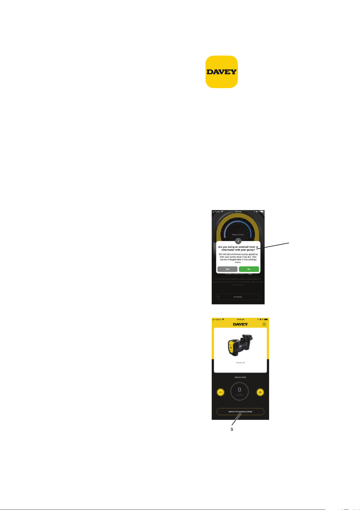
6. BLUETOOTH FUNCTIE
Bluetooth app set-up
• Open de "App Store" app op uw apparaat.
• Zoek de “Davey Pool Pump”
• Installeer de app op uw apparaat.
De app kan geïnstalleerd worden op zo veel apparaten als u wilt, maar de pomp kan maar met een apparaat
per keer bediend worden. De taal en de tijd van de app zijn hetzelfde als die van uw app instelling. De
meeteenheden worden automatisch ingesteld volgens de eenheden van de regio van uw apparaat, maar u
kunt kiezen tussen liters, gallons en m3/uur
Koppelen van een apparaat aan de pomp.
• Open de app op uw smart apparaat.
• Draai de knop op de pomp van "off" naar "Bluetooth", er gaat een seconde een wit led lampje branden.
• Druk op uw apparaat op de aansluitingsknop.
• ALLEEN als u de instelling voor de eerste keer uitvoert, kiest u "JA" om de lokalisatie toe te staan
• Als de apparaten voor de eerste keer worden gekoppeld, hebt u 2 minuten de tijd om dit te doen, daarna
moet de hele procedure herhaald worden.
Externe timer/chlorinator
Er verschijnt een pop-up venster dat u vraagt of u een
externe timer of chlorinator gebruikt voor de bediening van de
SilensorPRO. Kies "ja” of "nee" Dit is een beveiligingsfunctie
waardoor voorkomen wordt dat
de chlorinator gaat werken zonder dat de pomp functioneert.
Dit pop-up venster verschijnt
Opmerking: App screenshots worden alleen ter illustratie
weergegeven. De schermweergaves kunnen variëren.
Handmatige of geprogrammeerde modus
Er zijn twee modus beschikbaar, u kunt handmatig de
SilensorPRO bedien en of u kunt een werkingsprogramma
opstellen.
Handmatige modus
• In de geprogrammeerde modus drukt u op "overschakelen
naar handmatige modus"
• De app staat nu in de handmatige modus en u kunt handmatig
de snelheid aanpassen door te drukken op de (+/-)
• In de handmatige modus werkt de SilensorPRO op de
ingestelde snelheid, zelfs als de telefoon buiten bereik is.
• Elk keer dat de knop op Bluetooth wordt gezet, draait de
pomp na de priming cyclus op de eerder ingestelde snelheid.
Geprogrammeerde modus
• Er zijn twee opties (instellen van een dagelijkse cyclus of een
wekelijkse cyclus) die u kiest door op het gewenste vak te drukken.
SilensorPro BT
Om te schakelen tussen
de handmatige en geprogrammeerde modus
drukt u op deze knop.
• Met deze optie kunt u een standaard “dagelijks programma” creëren dat elke dag consistent werkt op de
ingestelde niveaus.
Nederlands
71
Page 72
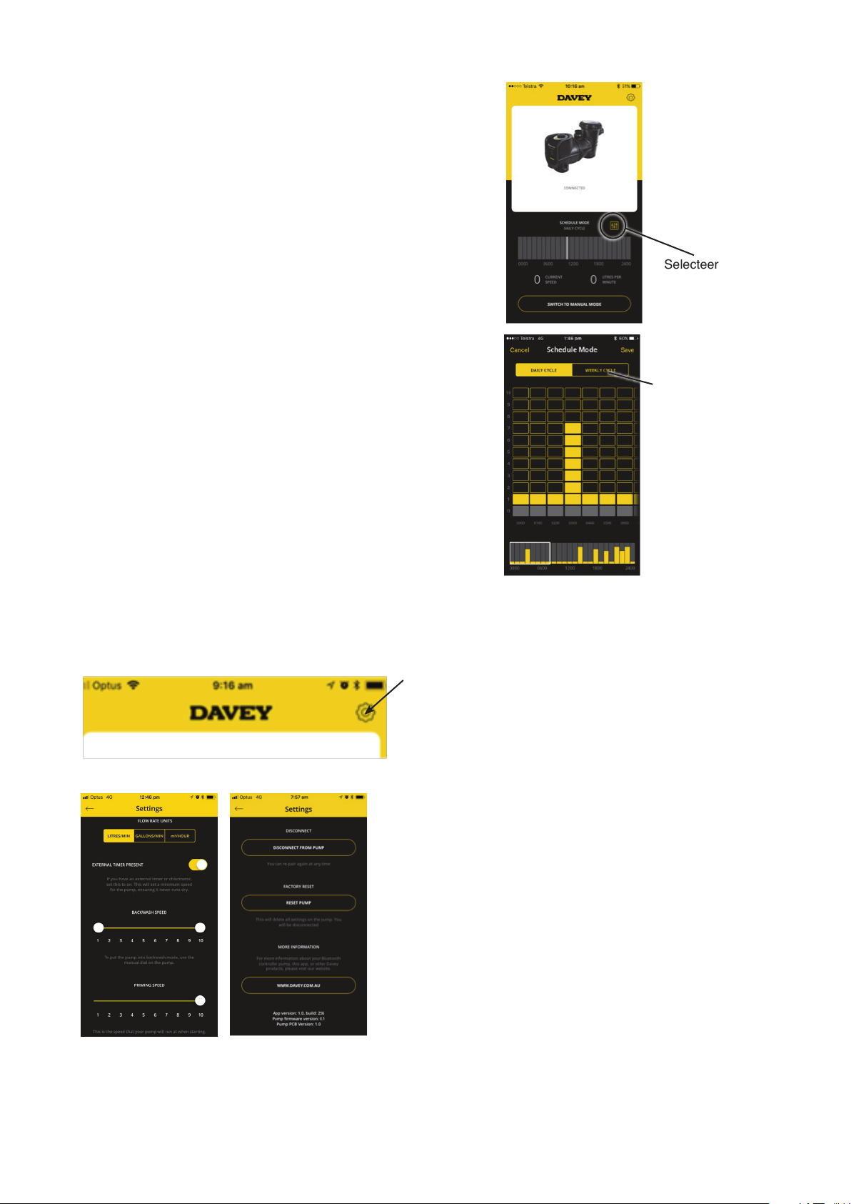
Er zijn twee opties (instellen van een dagelijkse cyclus of een
wekelijkse cyclus) die u kiest door op het gewenste vak te drukken.
Met deze optie kunt u een standaard “dagelijks programma”
creëren dat elke dat consistent werkt op de ingestelde niveaus.
• De “Wekelijkse cyclus” optie kan voor de hele week worden
ingesteld, zodat u de dagelijkse pompcycli in kunt stellen
afhankelijk van het weer, het aantal zwemmers, enz.
Instellen van een programma
• Kies het vakje dat overeenkomt met de tijd die de pomp in
werking moet zijn.
• Kies de snelheidsinstelling waarop u wilt dat de pomp steeds
werkt Opmerking: Instellen van de pomp (1-10) verwijst naar
langzaamste tot snelste werkingssnelheid van de pomp.
• Als u tevreden bent met het programma kiest u "Opslaan".
Communicatie tussen het apparaat en de pomp kan tot 20
seconden in beslag nemen afhankelijk van het gekozen
schema.
• De regel onderaan het scherm geeft aan op elke dag en welk
tijdstip het schema is aangeland. Dit samenvattingsscherm
kan gemakkelijk worden aangepast door de bovenstaande
kolommen omhoog of omlaag te swipen.
• Opmerking: Als u een chlorinator gebruikt, moet u ervoor
zorgen dat de "on" tijden van de pomp overeenkomen met
de "on" tijden van de chlorinator De pomp blijft in de laatst
gebruikte modus staan, ongeacht of dit de handmatige of de
geprogrammeerde modus is.
SilensorPro BT
Selecteer om de
instellingen aan te
passen
Kies de dagelijkse cyclus of
de wekelijkse
cyclus.
Instellingen
Om de set-up instellingen aan te passen, klikt u op het icoon instellingen.
Het volgende scherm verschijnt (scroll naar beneden op het scherm om alle informatie te bekijken).
Priming snelheid/Max snelheid
Bij elke start van de pompt vindt eerst een priming van 2 minuten plaats om ervoor te zorgen dat er water in
het systeem zit. De snelheid waarmee dit gebeurt, kan worden aangepast tussen 5 en 10. De snelheid die u
instelt, beperkt de maximale snelheid waarmee de pomp handmatig of in geprogrammeerde modus werkt.
Nederlands
72
Page 73

Backwash
Kan worden ingesteld op een enkele snelheid of in twee snelheden waarbij de pomp "pulst tussen de twee
instellingen. Minimale snelheid kan worden ingesteld tussen 1-10, maximale snelheid kan worden ingesteld
tussen 5-10.
“External Timer Present” (externe timer)
Zet dit aan of uit, afhankelijk van of u al dan niet een externe timer/chlorinator gebruikt.
Loskoppelen functie
De "loskoppelen van de pomp" functie kan worden gebruikt om:
• Met een ander apparaat de pomp te bedienen
• Los te koppelen zodat u niet automatisch aan de pomp verbonden wordt.
• Wij wijzen u erop dat de Bluetooth verbinding automatisch wordt verbroken na een minuut zonder
communicatie
“Factory Reset” (reset fabrieksinstellingen)
Hiermee wordt de pomp gereset in de fabrieksconfiguratie zodat u het set-up proces opnieuw uit kunt
voeren.
• Kies "reset pomp"
• Zet de knop op "off", en daarna op "Bluetooth"
• Daarna kunt u de pomp opnieuw aan uw telefoon koppelen. Deze procedure is
ingesteld om onopzettelijk resetten van de pomp te voorkomen.
SilensorPro BT
Pomp defecten zoeken
In geval van een defect verschijnt het volgende scherm waarop het defect met
daaronder de oplossing worden vermeld.
Naam defect Beschrijving defect
Controleer of de motor vrij kan draaien. Schakel 1
Pomp defect - zoeken
Pomp defect - te lage spanning
Pomp defect - te hoge temperatuur
Pomp defect - motor draait vertraagd
Pomp defect - onderbelasting/ prime verlies
minuut uit en schakel dan weer in om te resetten. Als het
probleem blijft bestaan, contact opnemen met Davey of
een erkende reparateur.
Probleem in het stroomnetwerk. Als de stroom weer
normaal is, een minuut uitschakelen en dan weer in om te
resetten.
Pomp is te heer Controleer de omgevingstemperatuur.
Stel in op de laagste snelheid als de
omgevingstemperatuur te hoog is.
Controleer of de motor vrij kan draaien. Schakel 1 minuut
uit en schakel dan weer in om te resetten.
Controleer of er genoeg water in de pomp zit. Schakel 1
minuut uit en schakel dan weer in om te resetten. Als het
probleem blijft bestaan, contact opnemen met Davey of
een erkende reparateur.
73
Nederlands
Page 74

Pomp defect - te hoge temperatuur motor; of
Pomp defect - te lage spanning; of
Pomp defect - aardlek defect; of
Pomp defect - systeem defect; of
Pomp defect -output fase defect; of
Pomp defect - vermogen overbelasting; of
Pomp defect – EEPROM checksum; of
Pomp defect – watchdog fout; or
Pomp defect – back EFM bescherming; of
Pomp defect - thermistor fout; of
Pomp defect - uitgeschakelde koppel; of
Pomp defect - interne bus communicatie; of
Pomp defect – applicatiefout; or
Pomp defect - IGTB temperatuur hoog; of
Pomp defect - 4mA analoge input fout; of
Pomp defect - externe fout; of
Pomp defect – keypad communicatie fout; or
Pomp defect – veldbus communicatie fout; or
Pomp defect – veldbus interface fout.
Schakel 1 minuut uit en schakel dan weer in om te
resetten. Als het probleem blijft bestaan, contact
opnemen met Davey of een erkende reparateur.
7. GEAVANCEERDE SETUP VAN DE SP400BT
Externe AUX aansluitingen overzicht
Uw SilensorPro SP400BT heeft een RJ45 stijl waterproof plug voor externe bediening van de motorsnelheid
en andere functies. U kunt een standaard RJ45 netwerkkabel (zonder boot) gebruiken.
Figuur 1: RJ45 plug geïnstalleerd in behuizing (achterkant)
Wij raden u aan de kabellengte tussen de pomp en de externe zwembadcontroller of verwarming zo kort
mogelijk te houden. Er zijn twee belangrijke pin configuraties zoals hieronder weergegeven:
RJ45 PINOUT
Figuur 2: RJ45 pin aansluitingen
Nederlands
74
Page 75

Pin Functie T-568A T-568B
1 RS485 +ve Groen/wit Oranje/wit
2 RS485 -ve Groen Oranje
3 Digitale input 3 Oranje/wit Groen/wit
4 Analoge input Blauw Blauw
5 0V DC Aarde Blauw/wit Blauw/wit
6 Digitale input 2 Oranje Groen
7 Digitale input 1 Bruin/wit Bruin/wit
8 24V Bruin Bruin
Controleer of de kabel die u gebruikt voldoet aan de bovenstaande kleurcode pinnen 1 tot en met 8 Als
een andere kleurcode wordt gebruikt, noteer dan de kleur die overeenkomt met elke pin om verkeerde
aansluiting op de zwembad controller of verwarming te voorkomen. Als een andere kabel wordt gebruikt,
zorg dan dat de analoge input en de aarde een gedraaid paar zijn.
De 24V aansluiting mag alleen worden gebruikt als referentie voor de digitale inputs - SLUIT GEEN externe
uitrustingen aan op deze aanvoerrail.
Digitale controle input
De 3-cijferige inputs maken het mogelijk de snelheidskeuze instelling te overriden. Om een van deze inputs
in te stellen:
• Sluit een geïsoleerde 24V toevoer aan tussen de DC aarde en de digitale input pin
• Sluit de geschakelde contacten van een relais aan tussen de 24V pin en de digitale output
De vaste snelheden (proportioneel aan volledige snelheid) zijn:
Input 1 (pin 7) Input 2 (pin 6) Input 3 (pin 3) Output snelheid
0 0 0 Kies
0 0 24V 33%
0 24V 0 50%
0 24V 24V Backwash
24V 0 0 100%
24V 0 24V 67%
24V 24V 0 83%
Interfacing uitrusting bij de SilensorPro SP400BT
WAARSCHUWING! Het onderstaande werk moet worden uitgevoerd door een
gekwaliceerde elektricien.
De SilensorPro SP400BT kan gecontroleerd worden via andere uitrustingen voor inschakeling van hoge
snelheid (of andere vooraf ingestelde snelheden, zie sectie 8 voor meer informatie). Hierdoor wordt
maximale efficiëntie verkregen, bijvoorbeeld bij gebruik van een gasverwarming of een verwarmingspomp.
Als de uitrusting een geïsoleerde 18-24V DC signaal output heeft, sluit u pin 7 aan op 24V DC positief en pin
5 op DC aarde zoals wordt weergegeven in het volgende diagram:
Pin7 (Brown/White)
To RJ45 Socket of VSD Pump
Pin5 (Blue/White)
Controlling Equipment
+ 18 ~ 24V DC
DC Ground
Nederlands
75
Page 76

Als de controle-uitrusting geen 18-24V output spanning heeft zoals hierboven vermeld, maar een 24V AC,
230V AC, 12V AC of 12V DC enz. signaal output, kan hiervoor een geschikte relais (de spoelspanning
moet hetzelfde zijn als het signaal output spanning van de controle-uitrusting) worden gebruikt, zoals
weergegeven in het volgende diagram:
Controlling Equipment
Pin7 (Brown/White)
To RJ45 Socket of VSD Pump
Pin8 (Brown)
Relay (Dry)
Contact
Relay Coil, must be
the same voltage
as the equipment
signal output
Als de controle-uitrusting al een relais output heeft (droogcontact) voor de controlefunctie, is een extra relais
niet nodig, sluit dan Pin 7 (bruin/wit) en Pin 8 (bruin) aan op de droge contacten zoals weergegeven in het
linkerdeel van het bovenstaande diagram.
Analoge controle input
Snelheidscontrole kan ook worden opgeslagen door aansluiting van een 0-10V signaal op de input op pin
4 (aarde op pin 5). Zodra een signaal boven 0V wordt geregistreerd, neemt deze input voorrang op alle
gekozen instellingen. Bijvoorbeeld 10V DC verandert de pompsnelheid tot 100%, 5V DC verandert de
pompsnelheid tot 50% etc.
Controlling Equipment
+ 0~ 10 V DC Signal Output
Pin4 (Blue)
To RJ45 Socket of VSD Pump
Pin5 (Blue/White)
of controlling equipment
DC Ground
8. TECHNISCHE SPECIFICATIES
Model
Max kop (m)
RPM
Behuizing klasse (IP)
Isolatieklasse
Voltage (V)
Stroom frequentie (Hz)
Motor inputvermogen: (W)
Werkingsgrenzen
Max watertemperatuur:
Max omgevingstemperatuur:
Snelheid 1 - 10: 1.500 – 3.600 Snelheid 1 - 10: 1.050 – 3.100
Snelheid 1: 128 Snelheid 1: 126
Snelheid 5: 524 Snelheid 5: 728
Snelheid 10: 1.111 Snelheid 10: 1.639
SP200BT SP400BT
20 26
Backwash instelling: variabel
45
F
220 - (240VAC)
50/60 Hz
Backwash instelling: variabel
40°C 40°C
50°C 50°C
76
Nederlands
Page 77

Afmetingen
A
C
B
D
G
F
E
A
305mm 670mm 320mm 350mm 65mm 230mm 380mm 200mm 250 mm 10mm 50/63 14
B C
D E F G H I
H
I
Montageopeningen
doorsnede
Inlet/Outlet
PVC
Netto
gewicht
(kg)
9. GEBRUIK VAN UW SILENSORPRO MET ZOUT WATER CHLORINATOR
Chlorinatoren vereisen een minimale waterflow door de chloreringscellen voor optimale efficiëntie en
levensduur van de cellen. Zie de handleiding van van de chlorinator voor richtlijnen voor de vereiste
flow voor uw zwembadsysteem. Controleer of de flow rate voldoende is voor volledige afdekking van uw
chloreringscellenplaten gedurende de volledige werkingsduur.
10. GEBRUIK VAN UW ZUIGREINIGER VOOR ZWEMBAD
Voordat u een zwembadreiniger installeert of koopt voor gebruik met uw SilensorPro moet u nagaan welke
minimale flow rates vereist zijn voor efficiënte werking.
Om een zuigreiniger voor zwembad te gebruiken:
• Activeer de high flow instelling (10) en laat de pomp volledig aanzuigen door 2 minuten te laten draaien.
Als de pomp volledig is aangezogen ziet u een sterke waterstroom via het transparante deksel van het
bladmandje.
• Als alle lucht uit het bladmandje verwijderd is, sluit u de slang van de zwembadreiniger stevig aan op de
skimmerplaat of de daarvoor bestemde wandafzuiging.
• Kies de snelheidsinstelling die het beste resultaat geeft voor uw zuigreiniger. Snelheid 3 tot 7 is voldoende
voor de meeste reinigers, als de reiniger meer nodig heeft, kiest u snelheid 7-10.
• De reiniger moet niet langer worden aangesloten dan noodzakelijk is voor het reinigen van uw zwembad.
Als het zwembad schoon is, sluit u de reiniger af en verwijdert u de skimmerplaat van de skimmer.
• Activeer opnieuw de meest efficiënte snelheidsinstelling voor dagelijkse filtering. Aanbevolen snelheid 1 tot 4.
OPMERKING: Voor optimale energie-efciëntie van uw SilensorPro moet u de
zuigreiniger NIET aangesloten laten als geen reiniging nodig is.
OPMERKING: Als de SilensorPRO is aangesloten op een timer of een andere
automatische controle, moet de bedrading door een gekwaliceerde elektricien worden
verwijderd.
• Sluit de waterventielen aan op de zwembadretour en de inlet van de SilensorPRO slangen.
• Verwijder de koppelingen van de afvoer- en afzuigslangen, let op dat u de o-ringen niet kwijt raakt.
• Verplaats de slangen met de daaraan bevestigde koppelingen tot de SilensorPRO vrij getrokken kan worden.
OPMERKING: Zorg dat u het modelnummer dat te vinden is op het plaatje op de motor,
bij de hand hebt als u informatie vraagt over uw SilensorPro.
Nederlands
77
Page 78

11. PROBLEEMOPLOSSING
Als de pomp draait, maar er geen of weinig water stroomt, kan het volgende van toepassing zijn:
• Het filter vereist backwashing of is verstopt. Zie de relevante sectie in de filterhandleiding
• U hebt de pomp niet aan laten zuigen. Laat de pomp opnieuw aanzuigen zoals vermeld in 'De pomp starten'
• Er zitten luchtlekken in de afzuigslangen Controleer alle slangen en repareer lekken, controleer ook of de
klep van het zeefmandje niet los zit. Luchtbellen in het water die terugstromen naar het zwembad wijzen
op een lek in de afzuiging naar de pomp waardoor er lucht in de slangen komt.
• Niet functioneren kan ook veroorzaakt worden door een lekkende afsluiting van de pompzuiger. Dit is het
geval als er zich water op de grond onder de pomp bevindt.
• De pomp kan geen water uit het zwembad krijgen. Controleer of de ventielen naar de pomp volledig open
zijn en of het zwembadwaterniveau tot aan de skimmer staat. Halverwege de voorkant van de skimmerbox
is voldoende;
• Verstopping in de slangen of de pomp. Verwijder het zeefmandje en controleer op verstopping bij de
ingang van de pompwaaier. Controleer de skimmer op verstopping.
Als de pomp niet werkt, kan het volgende van toepassing zijn:
• De stroom is niet aangesloten. Alleen voor -240 volt, controleer het stroompunt door een draagbare
applicatie aan te sluiten om na te gaan of er stroom beschikbaar is. Controleer ook de zekeringen en de
hoofdschakelaar;
• Automatische overbelasting geactiveerd. De pomp heeft een ingebouwde thermische overbelasting die
automatisch reset nadat de motor is afgekoeld na een oververhittingsperiode. Bepaal de oorzaak van de
activering van de overbelasting en corrigeer dit. Reset de pomp door de stroom 30 seconden UIT te schakelen.
• Verstopping verhindert rotatie van de pomp.
12. DE SILENSORPRO VAN DE SLANGEN AFKOPPELEN
Als u de SilensorPRO moet afkoppelen, volgt u de deze instructies:
• Schakel de stroom uit en verwijder de stekker uit het contact.
• Schroef de koppeling op de voorkant en bovenkant van de pomp los zodat de pomp niet meer aan de
slangen vast zit;
• Schuif de pomp opzij.
13. WATERKWALITEIT
AANBEVOLEN CHEMISCHE SAMENSTELLING ZWEMBADWATER
ZWEMBADWATER
EVENWICHT
Ideale lezing / Bereik 1 – 3
Om te verhogen
Vrij chloor
(ppm)
Verhoog de output
van de chlorinator.
Voeg chloor toe.
Verhoog de ltertijd.
pH
Zwembaden
met beton en
tegels: 7,4-7,6
Andere
oppervlakken:
7,2-7,4
Buffer of soda
triumcarbonaat)
toevoegen
Totale Alkaliniteit
TA
(ppm)
Beton en tegels -
80-120
Andere
oppervlakken -
125-150
Natriumbicarbonaat
toevoegen
Calciumhardheid
(ppm)
Beton en tegels -
200-275
Andere oppervlakken
-
100-225
Calciumchloride
toevoegen
Stabilisator –
Cyanuurzuur
(ppm)
25 – 50 4500 – 6000
Cyanuurzuur
toevoegen
Optimaal
zoutgehalte
(ppm)
toevoegen
Zout
Om te verlagen
Testfrequentie Wekelijk Wekelijk Wekelijk Wekelijk Geregeld Geregeld
Zoutzuur
toevoegen
Zoutzuur
toevoegen
of droog zuur
toevoegen
Zwembad
gedeeltelijk leeg
laten lopen en
bijvullen met minder
hard water om te
verdunnen.
Zwembad
gedeeltelijk
leeg laten
lopen en
bijvullen om te
verdunnen
Zwembad
gedeeltelijk
leeg laten
lopen en
bijvullen
om te
verdunnen
Nederlands
78
Page 79

Routine onderhoudstaken - voor een optimale levensduur van uw zwembaduitrusting
en uw persoonlijke veiligheid, controleert u elke week deze checklist. Schakel de pomp
eerst uit.
a. Zorg dat drukmeters goed werken en dat de werkingsdruk binnen de grenzen ligt
zoals op het product wordt gespeciceerd.
b. Zorg dat elke afzuigingang en de hoofddrain een deksel hebben die veilig is
bevestigd en goed werkt.
c. Zorg dat alle skimmers voorzien zijn van deksels die goed zijn bevestigd en goed
werken. Deze moeten om de 3 tot 4 jaar worden vervangen.
d. Verwijder verstoppingen of vuil uit het deksel van de hoofddrain.
e. Controleer minstens een keer per week of het skimmermandje en de pompmand vrij
zijn van bladeren en afval.
f. Verwijder obstructies en brandbaar materiaal rond de pompmotor.
g. Zorg dat alle bedradingsaansluitingen schoon zijn en dat de bedrading en de
elektrische uitrusting in goede staat verkeren. Beschadigde draden moeten
gerepareerd of vervangen worden door een gekwaliceerde elektricien zodra de
beschadiging wordt ontdekt.
h. Controleer het waterevenwicht en de gehaltes aan desinfectiemiddelen via uw
plaatselijke zwembad speciaalzaak.
ELEKTRISCHE AANSLUITING EN BEDRADING MOETEN WORDEN AANGESLOTEN
DOOR EEN ERKENDE ELEKTRICIEN
GEVAAR Gevaarlijke afzuiging. Blokkeer de wateringang in het ltersysteem niet met
een lichaamsdeel, de druk kan haar of lichaamsdelen vastzuigen en ernstig letsel of
overlijden tot gevolg hebben. Blokkeer de afzuiging niet.
Zet de pomp onmiddellijk uit als er iemand bekneld raakt.
Gebruik geen zwembaden, spa's of spabaden als een zuigerafsluiting kapot, is,
ontbreekt of los zit. Er moeten bij elke pomp twee zuigerafsluitingen en ingangen
verstrekt worden om beknelling in de zuiger te voorkomen.
Conform AS/NZS60335.2.41 informeren wij u dat deze pomp niet gebruikt mag worden
door kinderen of mensen met een handicap, en evenmin door kinderen gebruikt mag
worden als speelgoed.
Let op! Voeg niet rechtstreeks chemische middelen toe aan de skimmer. Het
toevoegen van onverdunde chemische stoffen kan de pomp en het lter beschadigen
en ongeldigheid van de garantie tot gevolg hebben.
79
Nederlands
Page 80

Davey garantie
Davey Water Products zijn inclusief een garantie die niet kan worden uitgesloten onder nationale wetgeving. U hebt
recht op vervanging of terugbetaling voor een groot defect en op vergoeding voor alle redelijk voorzienbare verlies
of schade U hebt recht op reparatie of vervanging van de goederen als deze niet van acceptabele kwaliteit zijn en dit
niet het gevolg is van een groot defect.
Davey Water Products Pty Ltd (Davey), 6 Lakeview Drive Scoresby VIC 3179 voorziet in de volgende garantie
met betrekking tot dit product. Davey garandeert dat onder voorbehoud van de onderstaande uitzonderingen en
beperkingen, het product vrij is van materiaal- en vervaardigingsdefecten gedurende een periode van 24 maanden
na de aankoopdatum (garantieperiode).
Als het product een defect vertoond voor het einde van de garantieperiode en Davey een materiaal- of
vervaardigingsdefect constateert in het product, zal Davey naar eigen inzicht:
1. het product of de defecte onderdelen kosteloos vervangen of repareren of
2. Ervoor zorgen dat het defecte product of onderdeel kosteloos wordt gerepareerd of vervangen door een
erkende reparateur.
Davey behoudt zich het recht voor defecte onderdelen van het product te vervangen door onderdelen of
componenten van soortgelijk kwaliteit, graad en samenstelling als geen identieke onderdelen of componenten
beschikbaar zijn. Goederen die worden aangeboden voor reparatie kunnen in plaats van reparatie, vervangen
worden door gerenoveerde goederen van hetzelfde type.
Garantieclaims:
1. Als er zich een defect voordoet dat gedekt wordt door de Garantie stelt Davey in eerste instantie voor dat
u contact opneemt met de dealer waar u het product hebt gekocht. U kunt ook contact opnemen met onze
Customer Servicelijn via 1300 367 866 in Australië, of 0800 654 333 in Nieuw-Zeeland, of schrijven naar Davey
op het bovenstaande adres; of e-mailen naar sames@davey.com.au..
2. Bij de garantieclaim moeten een aankoopbewijs en gegevens over het vermeende defect worden gevoegd.
3. Na ontvangt van uw claim zal Davey proberen uw probleem op te lossen, of als het product defect is, u
adviseren over de manier waarop u uw product kunt laten repareren, een vervangend product of terugbetaling
kunt verkrijgen.
4. Deze garantie is beperkt tot materiaal- en vervaardigingsdefecten van het product en is niet van toepassing op
gebruiksonderdelen of het vervangen van onderdelen vanwege slijtage.
Uitsluitingen:
De garantie is niet van toepassing indien:
1.
Het Product is gewijzigd, gerepareerd of onderhouden door een ander dan Davey of een erkende reparateur.
2. Davey geen defect vast kan stellen na het testen van het product.
3. Het product anders is gebruikt dan voor het doel waarvoor het is ontworpen.
4. Het product gebruikt is in ongebruikelijke omstandigheden qua temperatuur, water, vochtigheid, druk, belasting
of soortgelijke omstandigheden.
5. De koper geen originele of goedgekeurde onderdelen of accessoires heeft gebruikt.
6. Het productdefect het gevolg is van misbruik, verkeerd gebruik, nalatigheid of ongeval.
7. Het productdefect het gevolg is van de nalatigheid van koper om het product correct te onderhouden of
gebruiken.
8. De schade is veroorzaakt door het gebruik van chemische of reinigingsproducten die niet door Davey zijn goedgekeurd.
Indien uw Davey product reparatie of onderhoud vereist na de garantieperiode, kunt u contact opnemen met de
dichtstbijzijnde de Davey dealer of mailen naar het Davey Support Center.. Een volledige lijst van Davey dealers is te
vinden op onze website.
INTERNATIONAAL
Australisch
Ph: +613 9730 9124
Fax: +613 9753 4248
Email: export@davey.com.au
Davey Water Products Pty Ltd
Member of the GUD Group
ABN 18 066 327 517
AUSTRALIË
Hoofdkantoor
6 Lakeview Drive,
Scoresby, Australia 3179
Ph: 1300 232 839
Fax: 1300 369 119
Email: sales@davey.com.au
Website: davey.com.au
® Davey is a trademark of Davey Water Products Pty Ltd. © Davey Water Products Pty Ltd 2019.
Website: davey.com.au
EUROPA
ZAC des Gaulnes
355 Avenue Henri Schneider
69330 Meyzieu, France
Ph: +33 (0) 4 72 13 95 07
Fax: +33 (0) 4 72 33 64 57
Email: info@daveyeurope.eu
Website: daveyeurope.eu
NIEUW-ZEELAND
7 Rockridge Avenue,
Penrose, Auckland 1061
Ph: 0800 654 333
Fax: 0800 654 334
Email: sales@dwp.co.nz
Website: daveynz.co.nz
NOORD-AMERIKA
Ph: +1 866 328 7867
Email: export@davey.com.au
Website: daveyusa.com
MIDDEN OOSTEN
Ph: +971 50 6368764
Fax: +971 6 5730472
Email: info@daveyuae.com
Website: daveyuae.com
80
P/N 403308-1
Page 81

SilensorPRO SP200BT & SP400BT
Bomba para Piscina
Instruções de Instalação e
Funcionamento
50/60Hz
SP200BT
Por favor, consulte o website da Davey na sua região no verso deste
documento para ver todas as atualizações a informações sobre produtos.
Por favor, transmita estas instruções ao operador deste equipamento.
SP400BT
Inglês
Page 82

Parabéns pela sua compra de uma bomba SilensorPRO SP200BT ou SP400BT de alta qualidade. Todos os
componentes foram concebidos e fabricados de modo a proporcionarem uma operação fiável e sem problemas.
Índice:
1. INSTALAÇÃO DA BOMBA DE VELOCIDADE VARIÁVEL DA DAVEY .....................................................83
Ligação elétrica .........................................................................................................................................83
Ligação da canalização ............................................................................................................................84
2. DIAGRAMA DE INSTALAÇÃO TÍPICA .....................................................................................................85
3. ESPECIFICAÇÕES DE DESEMPENHO ..................................................................................................85
3.1 Desempenho hidráulico da SP200BT ................................................................................................ 85
3.2 Especificações Elétricas da SP200BT ................................................................................................86
3.3 Desempenho Hidráulico da SP400BT ................................................................................................86
3.4 Especificações Elétricas da SP400BT ................................................................................................86
4. MANUAL DO PROPRIETÁRIO ................................................................................................................87
Poupança de energia com a SilensorPRO ...............................................................................................87
Lista de controlo pré-arranque ..................................................................................................................87
Funcionamento com baixo consumo de energia ......................................................................................88
Diretrizes sobre as horas de funcionamento recomendadas para a bomba ............................................88
Esvaziar o cesto do filtro ...........................................................................................................................89
Manutenção de rotina ...............................................................................................................................89
5. CARACTERÍSTICAS E FUNCIONALIDADE ............................................................................................90
Indicador luminoso LED multicolorido ......................................................................................................90
Tecnologia de Ciclos da Velocidade de Contracorrente ...........................................................................90
Unidade de frequência variável total com marcação rápida selecionável amiga do utilizador .................90
Recipiente grande de 4,5 litros para detritos ............................................................................................90
Design patenteado de refrigeração a água para uma operação contínua e super silenciosa ..................90
Compensação de caudal/velocidade constante da SP400BT .................................................................90
Porta de Comunicações RJ45 hermética da SP400BT (consulte a secção 7 para ver os detalhes da ligação)
6. FUNCIONALIDADE BLUETOOTH ...........................................................................................................91
Configuração da Aplicação Bluetooth .......................................................................................................91
Emparelhamento de um dispositivo à bomba ...........................................................................................91
Temporizador Eterno / Clorador ................................................................................................................ 91
Modo de programação ..............................................................................................................................91
Definição de uma programação ................................................................................................................92
Definições .................................................................................................................................................92
Velocidade / velocidade máxima da preparação ......................................................................................92
Contracorrente ..........................................................................................................................................93
Hora externa presente ..............................................................................................................................93
Função desligar ........................................................................................................................................93
Reposição dos valores de fábrica .............................................................................................................93
Deteção de falhas da bomba ....................................................................................................................93
7. CONFIGURAÇÃO AVANÇADA DA SP400BT ..........................................................................................94
Descrição geral das ligações AUX externas .............................................................................................94
Entradas de controlos digitais ...................................................................................................................95
Equipamento de interface com a SilensorPRO SP400BT ........................................................................95
Entradas de controlos analógicos .............................................................................................................96
8. ESPECIFICAÇÕES TÉCNICAS ...............................................................................................................96
9. UTILIZAÇÃO DA SILENSORPRO COM UM CLORADOR DE ÁGUA SALGADA ....................................97
10. OPERAÇÃO DO ASPIRADOR DA PISCINA ............................................................................................97
11. RESOLUÇÃO DE PROBLEMAS ..............................................................................................................98
12. REMOÇÃO DA SILENSORPRO DA CANALIZAÇÃO ..............................................................................98
13. QUALIDADE DA ÁGUA ............................................................................................................................98
14. GARANTIA DA DAVEY ...........................................................................................................................100
.......90
82
Inglês
Page 83
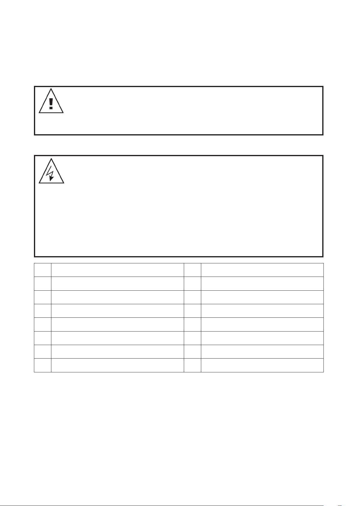
1. INSTALAÇÃO DA BOMBA DE VELOCIDADE VARIÁVEL DA DAVEY
A SilensorPRO deve ser instalada o mais próximo possível da água e montada sobre uma base firme numa
posição bem drenada, suficientemente elevada para impedir uma inundação. É da responsabilidade do
instalador/proprietário instalar a bomba num local em que a placa identificativa possa ser facilmente lida e a
SilensorPRO prontamente alcançada para fins de assistência. Recomenda-se que a SilensorPRO seja protegida
das condições climáticas. As caixas devem ser ventiladas de modo a impedir a acumulação de condensação.
O não cumprimento destas instruções e a não observância de todos os códigos
aplicáveis pode causar lesões corporais e/ou danos materiais graves.
Esta bomba requer uma experiência prossional para instalação e manutenção. A
instalação deste produto deve ser levada a cabo por uma pessoa com conhecimento
dos requisitos de chumbagem das piscinas e que siga as instruções de instalação
fornecidas neste manual.
Ligação elétrica
INFORMAÇÕES IMPORTANTES A sua SilensorPRO está duplamente isolada do circuito
de água. Se for necessária uma estrutura de ligação equipotencial, será fornecida uma
Tomada de Ligação Equipotencial. (Por favor, consulte os estatutos e/ou regulamentos
locais para saber quais as normas de cablagem equivalentes às AS/NZ 3000).
PRECAUÇÃO: No interesse da segurança, aconselhamos que todas as marcas e
tipos de bombas de piscina sejam instalados de acordo com as normas AS/NZS 3000,
conhecidas como as normas de cablagem nacionais, ou regulamentos standard
locais equivalentes. Todas as instalações elétricas deve ser levadas a cabo por um
eletricista qualicado. A Davey recomenda que todas as instalações sejam efetuadas
com interruptores diferenciais ou dispositivos de proteção contra corrente residual.
Corrente operacional nominal residual não superior a 30mA.
AVISO! Certique-se de que existe um interruptor de isolamento elétrico localizado com
acesso fácil, para que a bomba possa ser desligada em caso de emergência.
F NFC C 15-100 GB BS7671/1992
D DIN VDE 0100-702 EW EVHS-HD 384-7-702
A OVE 8001-4-702 H MSZ 2364-702:1994/MSZ 10-533 1/1990
E UNE 20460-7-702 1993, REBT ITC-BT-31 2002 M MSA HD 384-7-702.S2
IRL IS HD 384-7-702 PL PN-IEC 60364-7-702: 1999
I CEI 64-8/7 CZ CSN 33 2000 7-702
LUX 384-7.702 S2 SK STN 33 2000-7-702
NL NEN 1010-7.702 SLO SIST HD 384-7-702.S2
A SilensorPRO é adequada para ligação a uma fonte de alimentação nominal de 220 – 240 volt 50/60Hz e
está equipada de um cabo flexível. Se não estiver disponível uma tomada elétrica a uma distância de até
3 metros da bomba, terá de ser fornecida uma tomada de ligação de 3 pinos num local seguro e seco por
um eletricista. Os cabos de extensão à volta da piscina não são seguros e devem ser evitados. Se o cabo
de alimentação da SilensorPRO estiver danificado terá de ser substituído pela Davey ou por um agente
aprovado por peças sobressalentes genuínas da Davey.
A SilensorPRO incorpora um sistema de deteção de sobrecargas do motor, destinado a proteger o motor
contra sobreaquecimento. Se o motor ficar demasiado quente durante a operação, a respetiva velocidade
de funcionamento será reduzida de forma a baixar-lhe a temperatura até um valor aceitável e, assim,
aumentar a velocidade até ao valor originalmente definido.
Para repor a definição do motor, desligue a alimentação por 30 segundos e, em seguida, devolva a
alimentação a partir do interruptor da red.
83
Inglês
Page 84
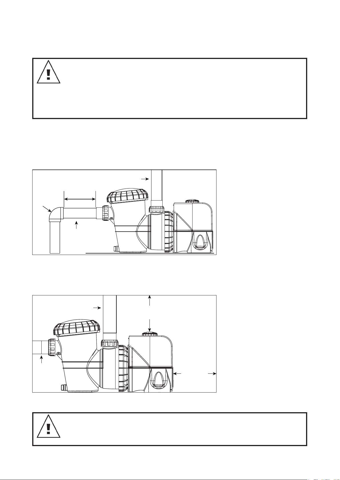
Ligação da Canalização
Figure 1.2
152mm
MINIMUM
76mm
MINIMUM
Suction line
50/63mm
Return to
Pool
50/63mm
Return to
São fornecidos conectores cilíndricos para a ligação da canalização à piscina. As bombas fora concebidas
para aceitar conectores em PVC de 50/63mm.
INFORMAÇÃO IMPORTANTE Se a SilensorPRO e o ltro estiverem localizados abaixo do
nível da água da piscina, é necessário instalar válvulas isoladoras no tubo entre a bomba e
a caixa do skimmer e no tubo de retorno do ltro até à bomba. Quando chumbar o tubo de
descarga, certique-se de que a canalização não interfere no marcador de velocidade da
bomba. Os conetores cilíndricos devem ser apertados manualmente. Não são necessários
vedantes, colas ou silicones.
As conexões da SilensorPRO são construidas em ABS. Certos compostos de junção de PVC
são incompatíveis com o ABS. Verique a adequabilidade dos compostos antes da utilização.
Não se recomenda a utilização de qualquer tubo menor do que os especificados acima. A tubagem de
sucção deve ficar livre de fugas de ar e altos e cavidades que possam causar dificuldades de sucção.
Para se alcançar a maior eficácia, a SilensorPRO deve ser instalada de forma a que a turbulência da
água seja limitada o mais possível. Conforme mostrado na figura 1.1, não instale um conector curvo de
90° mais próximo do que 250mm do conector cilíndrico de entrada. As válvulas isoladoras utilizadas onde
o equipamento está localizado abaixo do nível da água da piscina também não deve ser instalado a uma
distância inferior a 250mm do conector cilíndrico de entrada. Isto ajudará ao fluxo laminar.
A tubagem de descarga da saída da SilensorPRO deve ser ligada à conexão de entrada do filtro da piscina
(normalmente, na válvula de controlo do filtro). Conforme mostrado na figura 1.2, assegure uma folga
adequada acima da bomba para não haver interferência com a marcação rápida SilensorPRO. Utilize uma
válvula de regulação no tubo de descarga quando utilizar esta bomba para qualquer aplicação onde exista
uma altura suficiente até à canalização a seguir à bomba.
Figure 1.1
ELBOW
Figure 1.2
250mm
Suction line
50/63mm
Return to
Pool
50/63mm
Pool
50/63mm
152mm
MINIMUM
Suction line
50/63mm
76mm
MINIMUM
Não se esqueça de instalar válvulas de regulação quando efetuar a chumbagem com outra bomba. Esta
medida ajuda a prevenir a rotação inversa da turbina e do motor.
AVISO! A sucção da bomba é perigosa e pode prender e afogar ou eviscerar os banhistas.
Não bloqueie a sucção. Não ponha a funcionar piscinas, spas ou jacuzzis se faltar uma
cobertura de sucção ou se estiver quebrada ou solta. Têm de ser fornecidas duas coberturas
ou entradas de sucção para cada bomba, para se evitar o apresamento por sucção.
Inglês
84
Page 85

2. DIAGRAMA DE INSTALAÇÃO TÍPICA
ProMaster - PM200SV
Performance
Pool pump Media Filter
3. ESPECIFICAÇÕE DE DESEMPENHOS
3.1 Desempenho hidráulico da SP200BT
25
20
15
Total Head ( m )
10
5
Dial position No. 10
Dial position No. 9
Dial position No. 8
Dial position No. 7
Dial position No. 6
Dial position No. 5
Dial position No. 4
Dial position No. 3
Dial position No. 2
Dial position No. 1
0
0 50 100 150 200 250 300 350 400
Flow ( lpm )
0
036 9 12 15 18 21 24
3
Flow ( m
85
/h )
Inglês
Page 86
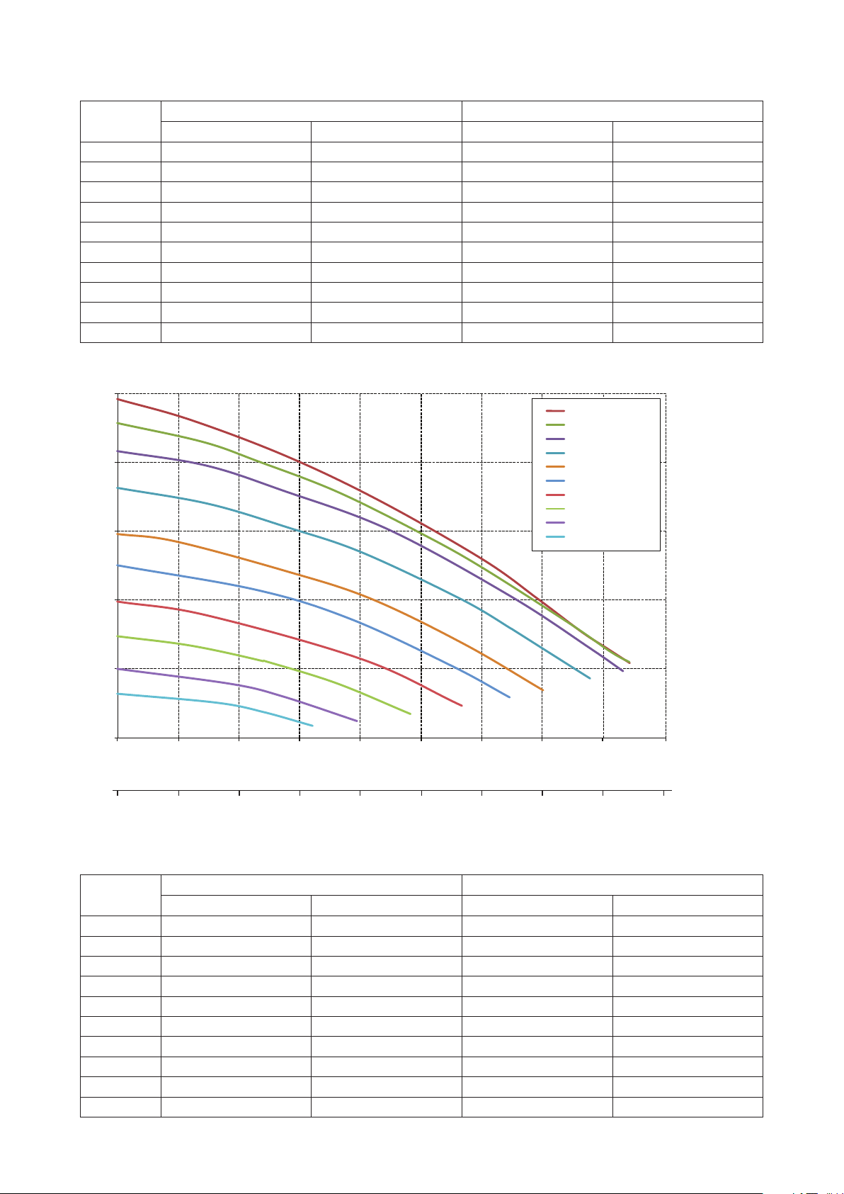
3.2 Especificações elétricas da SP200BT
450
Velocidade
Denição
Marcador 1 0,17 128 0,12 90
Marcador 2 0,28 207 0,19 145
Marcador 3 0,39 293 0,27 205
Marcador 4 0,53 398 0,37 279
Marcador 5 0,70 524 0,49 367
Marcador 6 0,87 655 0,61 459
Marcador 7 1,08 807 0,75 565
Marcador 8 1,25 936 0,87 655
Marcador 9 1,44 1.078 1,01 755
Marcador 10 1,48 1.111 1,04 778
hp W hp W
Entrada Saída
3.3 Desempenho hidráulico da SP400BT
25
Dial position No. 10
Dial position No. 9
Dial position No. 8
20
15
Dial position No. 7
Dial position No. 6
Dial position No. 5
Dial position No. 4
Dial position No. 3
Dial position No. 2
Dial position No. 1
Total Head ( m )
10
5
0
0 50 100 150 200 250 300 350 400
Flow ( lpm )
0
036 9 12 15 18 21 24 27
3
Flow ( m
/h )
3.4 Especificações elétricas da SP400BT
Velocidade
Denição
Marcador 1 0,17 126 0,12 89
Marcador 2 0,28 210 0,20 147
Marcador 3 0,46 347 0,32 243
Marcador 4 0,70 522 0,49 366
Marcador 5 0,97 728 0,68 510
Marcador 6 1,22 913 0,85 639
Marcador 7 1,61 1.211 1,13 848
Marcador 8 1,97 1.478 1,38 1.034
Marcador 9 2,18 1.635 1,59 1.191
Marcador 10 2,19 1.639 1,62 1.212
hp W hp W
Entrada Saída
86
Inglês
Page 87

4. MANUAL DO PROPRIETÁRIO
Esta SilensorPRO tem capacidade para Bluetooth, pelo que poderá definir e controlar as funções da bomba
a partir do seu dispositivo inteligente. Bluetooth é um protocolo de comunicação sem fios que permite a
comunicação entre dispositivos. Esta função é suportada por qualquer dispositivo que possa descarregar
uma aplicação da IOS ou Android App Store.
Leia estas instruções na íntegra antes de ligar esta bomba. Se tiver dúvidas quanto a qualquer uma destas
instruções, por favor, contacte a Davey para o número indicado no verso deste documento.
Cada SilensorPRO é exaustivamente testada na água com base em numerosos parâmetros de caudal,
pressão, tensão, corrente e mecânicos. A avançada tecnologia de fabrico de bombas da Davey proporciona
um desempenho fiável, eficiente e de longa duração da bombagem.
Poupança de energia com a sua SilensorPRO
A bomba de velocidade variável da Davey é uma bomba super eficiente que utiliza um motor de CA
inteligente, de última geração e infinitamente variável, que emite níveis de ruído e gases com efeito de
estufa mais reduzidos e implica custos de operação mais baixos do que as bombas de piscina tradicionais.
Devido à sua capacidade de funcionar a velocidades mais baixas do que as bombas convencionais,
a sua bomba também sofrerá menos uso e desgaste mecânico devido à menor pressão exercida nos
componentes mecânicos internos. É fácil alcançar uma operação de bombagem eficiente em termos
energéticos. Basta pôr a bomba de filtragem a funcionar a uma velocidade mais baixa, mas durante mais
tempo do que as bombas de velocidade fixa convencionais, de modo a “fazer circular” a água da piscina
para uma filtragem e higienização adequadas. O resultado é um consumo energético inferior e uma redução
de até 70% nos custos operacionais.
A SilensorPRO tem definições de velocidade ajustáveis, o que lhe permite variar a velocidade a que faz
circular a água da sua piscina ou spa As velocidades podem ser ajustadas de acordo com a alimentação de
um aspirador de piscina, sistema de limpeza no solo e aquecedores de piscina Pode ser selecionada uma
definição de contracorrente na bomba para efetuar a retrolavagem de um filtro de suporte.
O que esperar com a SilensorPRO (operação eficiente em termos energéticos) na sua piscina:
• Se a sua bomba SilensorPRO estiver a substituir uma bomba de motor CA tradicional, pode ter de a deixar
a funcionar durante mais tempo do que a sua antiga bomba de velocidade fixa. Esta situação é NORMAL
e ajuda-o ao poupar energia quando utilizar definições de velocidades inferiores.
• Também pode notar que o manómetro do filtro indica uma pressão muito mais baixa do que está
habituado. Isto também é NORMAL. A pressão de sistema mais baixa é simplesmente resultado da
redução da velocidade e taxa de caudal produzidos pela bomba.
• Durante o funcionamento a definições de velocidade mais baixas, também irá notar uma redução
significativa no ruído emitido pela bomba. Esta é uma grande vantagem para si, já que lhe permite pôr a
funcionar a sua SilensorPRO fora das horas de pico do consumo elétrico, o que também ajuda a reduzir
os seus custos de operação. Além disso, terá vizinhos muito mais felizes.
Muitos produtos para piscina baseiam-se em taxas de caudal mínimas para uma melhor operação e/ou
eficiência. Se estiver a utilizar definições de baixo caudal na SilensorPRO (ex., velocidade 1 a 4), a Davey
recomenda-lhe que verifique a compatibilidade da velocidade ou a taxa de caudal mínima necessária para
pôr a funcionar equipamento específico da piscina, como:
• Aspiradores de piscina;
• Geradores de ozono;
• Sistemas de aquecimento;
• Células do clorador de água salgada;
• Sistemas de limpeza no solo da piscina.
Lista de controlo pré-arranque
• A definição de velocidade escolhida é uma definição compatível com outro equipamento da piscina;
• A bomba está instalada num ambiente seguro e seco;
• O suporte da bomba tem um sistema de drenagem adequado em caso de fuga;
• Todas as fichas de transporte são removidas;
• A canalização está corretamente vedada e apoiada
• A bomba foi corretamente preparada;
• A fonte de alimentação está corretamente ligada
• Foram tomadas todas as medidas para um funcionamento seguro;
• O filtro foi instalado com um tubo de 50/63mm;
• As definições de programação (app) correspondem a quaisquer outros itens do sistema.
87
Inglês
Page 88

Funcionamento com baixo consumo de energia
A sua SilensorPRO SP200BT tem definições de velocidade de 1,500 a 3,600rpm. A SilensorPRO SP400BT
tem definições de velocidade de 1,050 a 3,100rpm. Sendo a velocidade 1 a mais baixa e 10 a mais alta.
• A velocidade 1 permite a velocidade mais baixa e, consequentemente, a máxima eficacia e poupança
energéticas.
Operação
Retrolavagem do filtro de suporte
Filtragem da Piscina
Funcionamento do aspirador da piscina
Limpeza manual da piscina
Operação da Função Água
Funcionamento do Spa Jet
Sistemas de limpeza no solo da piscina
Aquecimento solar da piscina
Definição de Velocidade Recomendada
Velocidade da Contracorrente
Velocidade 1 a 4
Velocidade 5 a 8
Velocidade 9 a 10
Diretrizes para as horas de funcionamento recomendadas para a bomba
A taxa de rotação para uma piscina residencial típica deve é uma taxa de rotação única do volume total da
água da piscina, no período diário em que a a bomba funcionaria normalmente. A tabela em baixo fornece
um guia apenas para as horas de funcionamento da sua bomba enquanto estiver no modo de filtragem, a
fim de alcançar a taxa de rotação mínima:
SilensorPRO SP200BT
Tamanho da piscina
(Litros)
Velocidade 1 Velocidade 5 Velocidade 10
Definição de Velocidade (horas)
20.000 3,3 1,7 1,1
30.000 5,0 2,5 1,7
40.000 6,7 3,3 2,2
50.000 8,3 4,2 2,8
60.000 10,0 5,0 3,3
80.000 13,3 6,7 4,4
100.000 16,7 8,3 5,6
SilensorPRO SP400BT
Tamanho da piscina
(Litros)
20.000 2,4 1,3 0,9
30.000 3,7 2,0 1,4
40.000 4,9 2,7 1,9
50.000 6,1 3,3 2,3
60.000 7,4 4,0 2,8
80.000 9,8 5,3 3,8
100.000 12,3 6,7 4,7
Definição de Velocidade (horas)
Velocidade 1 Velocidade 5 Velocidade 10
88
Inglês
Page 89

Nos termos da norma EN60335.1, somos obrigados a informá-lo de que este aparelho
pode ser utilizado por crianças com idades acima dos 8 anos e por pessoas com
capacidades físicas, sensoriais ou mentais reduzidas, ou com falta de experiência e
conhecimento, se tiverem recebido supervisão ou instruções sobre a utilização do
aparelho de uma forma segura e compreendam os perigos envolvidos. As crianças
devem ser vigiadas para assegurar que não brincam com o aparelho.
Esvaziar o cesto do filtro
O cesto do filtro deve ser inspecionado frequentemente através da tampa transparente e esvaziado quando
for evidente uma acumulação de sujidade. As instruções abaixo devem ser seguidas.
• Desligue a bomba;
• Desaparafuse a tampa do cesto do filtro no sentido contrário ao dos ponteiros do relógio e remova-a;
• Remova a tampa do cesto do filtro levantando-a e retirando-a do suporte;
• Esvazie os detritos acumulados no cesto. Lave-os com uma mangueira, se necessário.
NOTA: NUNCA bata com o cesto de plástico numa superfície dura, pois pode causar
danos.
• Verifique se o cesto do filtro tem rachas e substitua-o na bomba se estiver danificado;
• Substitua a tampa e certifique-se de que fica hermeticamente fechada no grande o-ring de borracha. É
forçoso apertá-la manualmente com firmeza. O O-ring & e o fio podem ser lubrificados com Hydra slip ou
produtos equivalentes.
Qualquer falha de cumprimento da manutenção regular pode causar danos não
abrangidos pela garantia.
Manutenção de rotina
Para maximizar a vida da SilensorPRO, e por motivos de segurança pessoal, utilize esta lista de controlo
uma vez por semana. Certifique-se de que a bomba está desligada antes de a pôr a funcionar:
• Certifique-se de que os manómetros estão a funcionar devidamente e que a pressão operacional se
encontra dentro dos limites conforme especificados no produto;
• Certifique-se de que cada entrada de sucção e o dreno principal tem uma cobertura que está firmemente
ligada e em condições de funcionamento seguras.
• Certifique-se de que todas as coberturas dos skimmers estão firmemente ligadas e em condições de
funcionamento seguras. Estas devem ser substituídas de 3 em 3 ou de 4 em 4 anos;
• Remova quaisquer obstruções ou detritos da cobertura do dreno principal;
• Certifique-se de que os cestos do skimmer e da bomba não contêm folhas e detritos, pelo menos, uma
vez por semana;
• Remova quaisquer obstruções e materiais combustíveis que possam existir em redor do motor da bomba;
• Certifique-se de que todas as ligações elétricas estão limpas e que todos os cabos e equipamentos
elétricos estão em boas condições. As ligações danificadas devem ser reparadas ou substituídas por um
eletricista credenciado logo que os danos sejam detetados;
• Verifique o equilíbrio da água e os níveis do desinfetante na sua loja local de produtos para piscina.
89
Inglês
Page 90

5. CARACTERÍSTICAS E FUNCIONALIDADE
A SilensorPRO tem várias características operacionais. Segue-se uma explicação das mesmas.
Indicador luminoso LED multicolorido
Utilizado para identificar definições necessárias referentes ao tempo e avisos de programação do ciclo da
velocidade máxima (Impulso):
• Verde sólido = Operação de marcação normal
• Verde com intermitência lenta = No modo de contracorrente
• Verde com intermitência rápida = Controlo externo AUX
• Branco Sólido = Hora de Executar a Retrolavagem
• Branco com intermitência rápida = Falha detetada - redefinir bomba
• Azul com intermitência lenta = Operado por Bluetooth
• Azul sólido = Modo Bluetooth
Tecnologia de ciclos de velocidade da contracorrente
Quando se encontra em modo de retrolavagem, a SilensorPRO entra em ciclo entre uma velocidade
baixa e alta para ajudar a agitar o suporte do filtro para uma limpeza mais eficaz. Esta ação reduz a água
desperdiçada e os químicos durante o processo dos ciclos de retrolavagem.
Unidade de frequência variável completa com marcação rápida
selecionável amiga do utilizador
• Permite uma seleção fácil da velocidade de filtragem pretendida
• Sem controlos digitais complicados por botões de pressão
Recipiente grande de 4,5 litros para detritos
• Permite intervalos maiores entre limpezas
Design patenteado de refrigeração a água para uma operação contínua
e super silenciosa
A SilensorPRO tem uma membrana e camisa refrigerada a água à volta do motor que ajuda a bomba a
arrefecer durante o funcionamento. O calor residual que sai do motor é transferido para a água da piscina,
ajudando a reduzir os custos energéticos de aquecimento da piscina.
Compensação de caudal/velocidade contante da SP400BT
À medida que o filtro da piscina fica sujo, vai-se acumulando pressão. Com uma bomba típica de piscina,
isto abrandaria naturalmente o caudal que passa pelo sistema. A SilensorPRO tem inteligência para
detetar automaticamente a resistência aplicada por um filtro e compensar lentamente a redução de caudal,
aumentando a velocidade do motor. O resultado é o caudal permanecer constante entre limpezas de filtros.
Quando a SilensorPRO detetar que o aumento de velocidade indica a hora da retrolavagem do filtro, o
indicador LED mostrará um visor branco sólido (consulte o item supra).
Porta de comunicações RJ45 hermética da SP400BT
(consulte a secção 7 para ver os detalhes da ligação)
• Para comunicação e ligação a sistemas de controlo de piscinas externos
• Para receber um sinal de uma bomba de aquecimento, ou aquecedor a gás para aumentar a velocidade
da SilensorPRO até ao valor máximo durante o processo de aquecimento
• Diagnósticos de assistência e atualizações de software (apenas para utilização pela Davey)
Inglês
90
Page 91

6. FUNCIONALIDADE DO BLUETOOTH
Configuração da aplicação Bluetooth
• Abra a aplicação “App Store” que está disponível no seu dispositivo.
• Procure “Davey Pool Pump”("Bomba de Piscina Davey")
• Instale a aplicação no seu dispositivo.
A aplicação pode ser instalada em todos os dispositivos pretendidos, mas apenas um deles pode controlar
a bomba em determinado momento. O idioma e a hora da aplicação são os mesmos da definição do seu
dispositivo. As unidades de medida assumem imediatamente as predefinições das unidades regionais do
seu dispositivo, mas pode optar entre Litros, Galões ou m
Emparelhamento de um dispositivo à bomba
• Abra a aplicação no seu dispositivo inteligente.
• Mude o marcador da bomba de “off” para “Bluetooth” e verá o LED branco intermitente durante um
segundo.
• No seu dispositivo, prima o botão de ligação.
• APENAS quando estiver a efetuar a configuração pela primeira vez, selecione “YES” ("SIM") para permitir
a localização.
• Por favor, tenha em atenção que, da primeira vez que os dispositivos são emparelhados, existe um limite
de tempo de 2 minutos para o fazer antes de o procedimento ter de ser repetido.
3
/hr.
Temporizador externo / clorador
Aparece uma janela sobreposta a perguntar-lhe se está a
utilizar um temporizador externo ou clorador, para controlar
a SilensorPRO. For favor, selecione “sim”, “não”. Esta é uma
função de segurança que ajuda a assegurar que o clorador só
funciona quando a bomba está a funcionar.
Nota: As imagens de ecrã da aplicação destinam-se apenas
a fins de demonstração. Os ecrãs reais podem variar.
Modo manual ou programado
Estão disponíveis dois modos, dependendo se pretende operar
manualmente a SilensorPRO ou, como alternativa, criar uma
programação da operação.
Modo manual
• Se estiver no modo de programação, prima “mudar para o
modo manual”
• A aplicação estará em modo manual e pode ajustar
manualmente a velocidade premindo os botões (+/ -).
Esta janela emergente
mostrará
SilensorPro BT
• No modo manual, a SilensorPRO funcionará à velocidade
definida, mesmo que o telefone esteja fora do alcance.
• Sempre que o marcador for mudado para a posição
Bluetooth, ela funcionará à velocidade anterior após o ciclo de
preparação.
Modo de programação
• Existem duas opções (definir um ciclo diário ou semanal), basta premir a caixa correspondente.
• Esta opção permite-lhe criar uma “programação diária” standard, que fará a bomba operar diariamente de
forma consistente nos níveis definidos;
Para mudar entre o
modo manual ou de
programação, pode premir este botão.
Inglês
91
Page 92

Existem duas opções (definir um ciclo diário ou semanal), basta
premir a caixa correspondente. Esta opção permite-lhe criar
uma “programação diária” standard, que fará a bomba operar
diariamente de forma consistente nos níveis definidos
• A opção “ciclo semanal” pode ser definida para toda a semana,
dando-lhe a possibilidade de alterar diariamente os ciclos da
bomba, dependendo das condições climáticas, do número de
banhistas, etc.
Definição de uma programação
• Selecione a caixa correspondente à hora em que pretende que
a bomba funcione;
• Selecione a definição de velocidade em que pretende que a
bomba funcione em qualquer momento. Nota: As definições
da bomba (1-10) referem-se à velocidade de operação da
bomba, da mais baixa à mais alta;
SilensorPro BT
Selecione a edi-
ção das denições
de programação
• Quando estiver satisfeito com a programação, selecione
“Save" ("Guardar”). As comunicações entre o dispositivo e
a bomba podem demorar até 20 segundos, dependendo da
programação selecionada;
• A fila na parte inferior do ecrã indica um resumo do ponto em
que se encontra a programação por dia e hora. Este ecrã de
resumo pode ser facilmente alterado deslizando para cima ou
para baixo as colunas em cima;
• Nota: Se utilizar um clorador, tem de assegurar que as horas
em que a bomba está “ligada” correspondem às horas em
que está “ligada” no clorador. A bomba permanecerá no último
modo utilizado, quer seja o modo manual ou programado.
Selecione se pretende o ciclo diário ou semanal.
Definições
Para alterar as definições de configuração, clique no ícone de definições:
Assim, visualizará os seguintes ecrãs (desloque o ecrã para baixo para ver todas as informações).
Velocidade de preparação / velocidade máx
Sempre que a sua bomba arranca, passa por 2 minutos de preparação, para assegurar que existe água no
sistema. Pode ajustar a velocidade a que ela executa esta operação entre 5 e 10. A velocidade que definir
limitará a velocidade máxima à qual a bomba funcionará no modo manual ou programado.
Inglês
92
Page 93

Retrolavagem
Pode ser definida como uma única velocidade, ou como alternativa, podem ser definidas duas velocidades e
a velocidade da bomba “pulsará” entre as duas definições. A velocidade mínima pode ser definida entre 1-10
e a velocidade máxima só pode ser definida entre 5-10.
Hora externa presente
Ative ou desative esta opção, consoante esteja a utilizar ou não um temporizador externo / clorador.
Função desligar
A função “desligar da bomba” pode ser utilizada para:
• Permitir que outro dispositivo controle a bomba;
• Desligar de modo a impedir que ligue a bomba automaticamente;
• Por favor, note que a ligação Bluetooth desligar-se-á automaticamente após um minuto sem comunicação.
Reposição dos valores de fábrica
Esta opção reporá as configurações de fábrica da bomba e permite-lhe reiniciar o
processo de configuração.
• Selecione “reset pump" ("redefinir bomba”);
• Rode o marcador para a posição “desligado” e, em seguida, para “Bluetooth”;
• Em seguida, pode emparelhá-lo com o seu telemóvel. Este procedimento é
aplicado para que a bomba não possa ser redefinida acidentalmente.
SilensorPro BT
Deteção de falha da bomba
Na eventualidade de ocorrer uma falha, será apresentado o seguinte ecrã, com
uma descrição de texto abaixo da falha, a indicar como resolvê-la.
Título da falha Descrição da falha
Verifique se o motor pode rodar livremente.
Desligue-o por 1 minuto e volte a ligá-lo para
Falha da bomba – sobretensão
Falha da bomba – subtensão
Falha da bomba – temperatura excessiva
Falha da bomba – motor parado
reiniciar. Se o problema persistir, contacte
a Davey ou um agente de reparações
autorizado.
Problema da tensão de alimentação. Quando
a alimentação for reposta no valor normal,
desligue-a por 1 minuto e volte a ligá-la
para reiniciar.
A bomba está quente demais. Verifique a
temperatura ambiente. Defina a velocidade
mais baixa possível se a temperatura
ambiente for demasiado elevada.
Verifique se o motor pode rodar livremente.
Desligue-o por 1 minuto e volte a ligá-lo para
reiniciar.
Falha da bomba – subcarga/perda da preparação
Verifique se existe água suficiente dentro
da bomba. Desligue-a por 1 minuto e volte
a ligá-la para reiniciar. Se o problema
persistir, contacte a Davey ou um agente de
reparações autorizado.
Inglês
93
Page 94

Falha da bomba – temperatura excessiva no motor; ou
Falha da bomba – sobretensão; ou
Falha da bomba – falha da ligação à terra; ou
Falha da bomba – falha do sistema; ou
Falha da bomba – falha da fase de saída; ou
Falha da bomba – sobrecarga de corrente; ou
Falha de bomba – some de controlo de EEPROM; ou
Falha da bomba – erro do dispositivo de fiscalização; ou
Falha da bomba – proteção traseira do EFM; ou
Falha da bomba – falha do termístor; ou
Falha da bomba – binário de segurança desligado; ou
Falha da bomba – comunicação do bus interno; ou
Falha da bomba – erro da aplicação; ou
Falha da bomba – temperatura elevada do IGBT; ou
Falha da bomba – Falha da entrada analógica de 4mA; ou
Falha da bomba – falha externa; ou
Falha da bomba – erro de comunicação do teclado; ou
Falha da bomba – erro de comunicação do fieldbus; ou
Falha da bomba – erro de interface do fieldbus.
Desligue-o por 1 minuto e volte a ligá-lo para
reiniciar. Se o problema persistir, contacte
a Davey ou um agente de reparações
autorizado.
7. CONFIGURAÇÃO AVANÇADA DA SP400BT
Descrição geral das ligações AUX externas
A sua SilensorPRO SP400BT tem uma tomada hermética estilo RJ45 para permitir o controlo externo da
velocidade do motor e outras funcionalidades. Pode ser utilizado um cabo de rede RJ45 standard (sem
conector).
Figura1 Ficha RJ45 instalada na caixa (da retaguarda)
É recomendável manter o comprimento do cabo entre a bomba e o controlador ou aquecedor externo da
piscina o mais curto possível. Existem duas configurações de pinos principais, conforme mostrado em baixo:
SAÍDA DE PINOS RJ45
Figura 2: Conexões de pinos RJ45
Inglês
94
Page 95

Pino Função T-568A T-568B
1 RS485 +ve Verde/branca Laranja/branca
2 RS485 -ve Verde Laranja
3 Entrada digital 3 Laranja/branca Verde/branca
4 Entrada analógica Azul Azul
5 Ligação à terra CC de 0V Azul/branca Azul/Branca
6 Entrada digital 2 Laranja Verde
7 Entrada digital 1 Castanha/branca Castanha/branca
8 24V Castanha Castanha
Verifique se o cabo que está a utilizar tem os pinos de codificação coloridos conforme mostrado em cima, de
1 a 8. Se já tiver sido utilizada uma codificação colorida alternativa, certifique-se de que registou a cor a que
corresponde cada pino, para evitar ligações incorretas no controlador ou aquecedor da piscina. Se for utilizado
um cabo alternativo, certifique-se de que a entrada analógica e a ligação à terra são um par entrançado.
A ligação de 24V só deve ser utilizada como referência para as entradas digitais – NÃO alimente
equipamento externo a partir desta calha de alimentação.
Entradas de controlo digital
As 3 entradas digitais permitem a substituição da definição da velocidade de marcação. Para definir uma
destas entradas, pode optar por:
• Ligue uma fonte de 24V isolada entre a ligação à terra CC e o pino da entrada digital
• Ligue os contactos comutados de um relé entre o pino de 24V e a entrada digital
As velocidades fixas (como uma proporção da velocidade total) são:
Entrada 1 (Pino 7) Entrada 2 (Pino 6) Entrada 3 (Pino 3) Velocidade de Saída
0 0 0 Marcador
0 0 24V 33%
0 24V 0 50%
0 24V 24V Retrolavagem
24V 0 0 100%
24V 0 24V 67%
24V 24V 0 83%
Equipamento de interface para a SilensorPRO SP400BT
AVISO! É necessário um eletricista qualicado para levar a cabo o trabalho mostrado a
seguir.
A SilensorPRO SP400BT pode ser controlada por outro equipamento para a ligar numa velocidade elevada
(ou qualquer outra velocidade pré-definida, consulte a secção 8 para ver detalhes). Esta vantagem permite
atingir a máxima eficácia, por exemplo, quando utiliza um aquecedor a gás ou uma bomba de aquecimento.
Se o equipamento tiver uma saída de sinal CC isolada de 18- 24V isolada, basta ligar o pino 7 ao polo
positivo CC de 24V e o pino 5 à ligação à terra CC, conforme mostrado no seguinte diagrama:
Controlling Equipment
Pin7 (Brown/White)
To RJ45 Socket of VSD Pump
Pin5 (Blue/White)
+ 18 ~ 24V DC
DC Ground
Inglês
95
Page 96
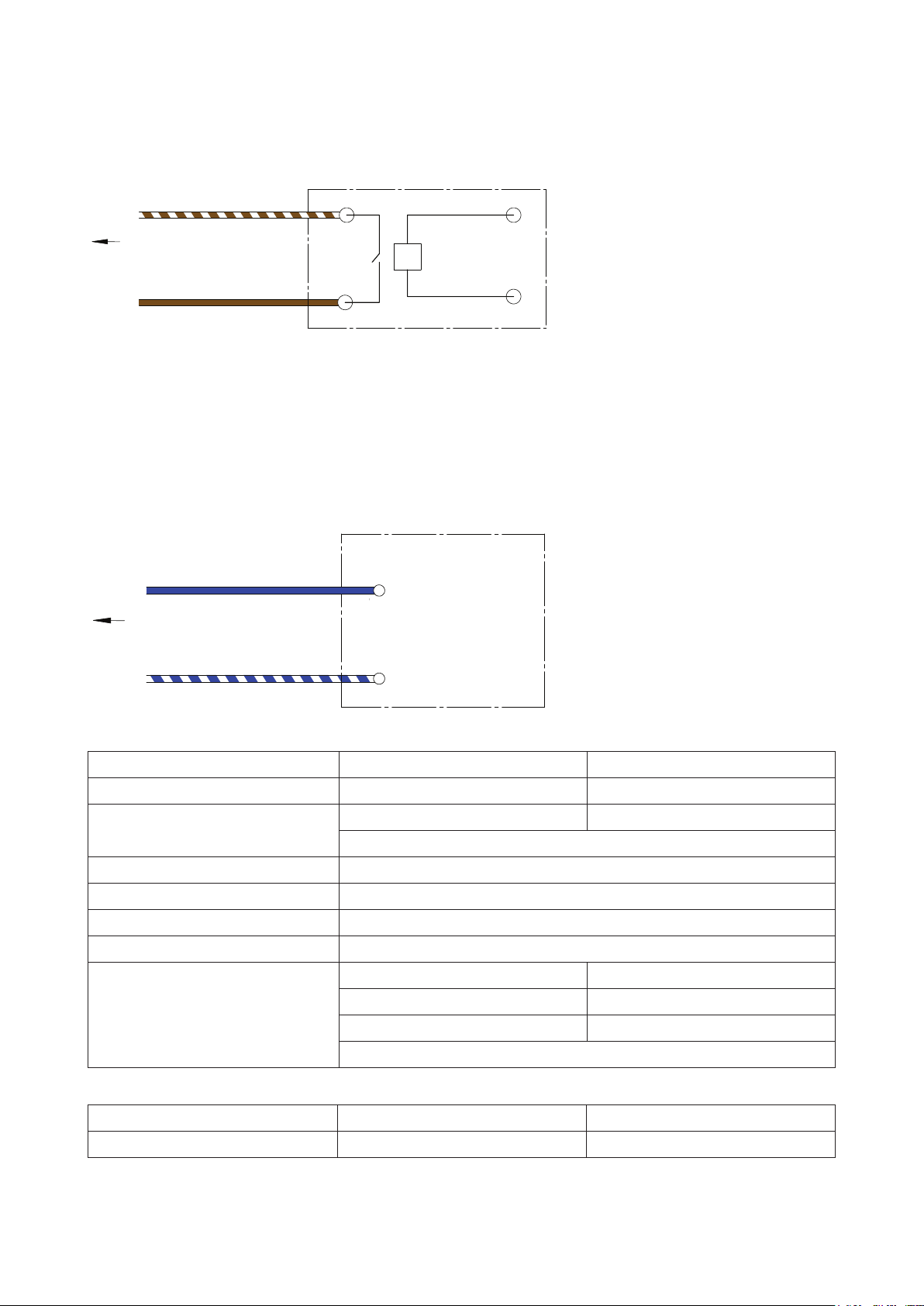
Se o equipamento de controlo não tiver uma saída de tensão CC de 18-24V conforme mostrada em cima,
mas tiver uma saída de sinal CA de 24V, CA de 230V, CA de 12V ou CC de 12V, etc., pode ser utilizado um
relé adequado (a tensão da bobina tem de ser igual à tensão da saída de sinal do equipamento de controlo)
para executar esta operação conforme mencionada em cima e mostrada no seguinte diagrama:
Controlling Equipment
Pin7 (Brown/White)
To RJ45 Socket of VSD Pump
Pin8 (Brown)
Relay (Dry)
Contact
Relay Coil, must be
the same voltage
as the equipment
signal output
Se o equipamento de controlo já tiver a saída do relé (contacto seco) para fins de controlo, não é necessário
um relé adicional, basta ligar o Pino 7 (Castanho/Branco) e o Pino 8 (Castanho) aos contactos secos
conforme mostrado na parte à esquerda do diagrama supra.
Entradas de controlo analógico
O controlo de velocidade também pode ser alcançado ligando-se um sinal CC de 0-10V à entrada do pino 4
(ligação à terra no pino 5). Logo que seja registado um sinal superior 0V, esta saída toma prioridade sobre
as definições de marcação. Por exemplo, uma CC de 10V alterará a velocidade da bomba para 100%, uma
CC de 5V alterará a velocidade da bomba para 50%, etc.
Controlling Equipment
+ 0~ 10 V DC Signal Output
Pin4 (Blue)
To RJ45 Socket of VSD Pump
Pin5 (Blue/White)
of controlling equipment
DC Ground
8. ESPECIFICAÇÕES TÉCNICAS
Modelo
Tam máx da cabeça (m)
RPM
Classe do cárter (IP)
Classe de isolamento
Tensão (V)
Freq de alimentação (Hz)
Potência de entrada do motor: (W)
Limites Operativos
Temperatura máx da água:
Tempetatura máx ambiente:
Dimensões
Velocidade 1 – 10: 1,500 – 3,600 Velocidade 1 – 10: 1,050 – 3,100
Velocidade 1: 128 Velocidade 1: 126
Velocidade 5: 524 Velocidade 5: 728
Velocidade 10: 1.111 Velocidade 10: 1.639
SP200BT SP400BT
20 26
Velocidade da retrolavagem: variável
45
F
220 – 240VAC
50/60 Hz
Velocidade da retrolavagem: variável
40°C 40°C
50°C 50°C
96
Inglês
Page 97
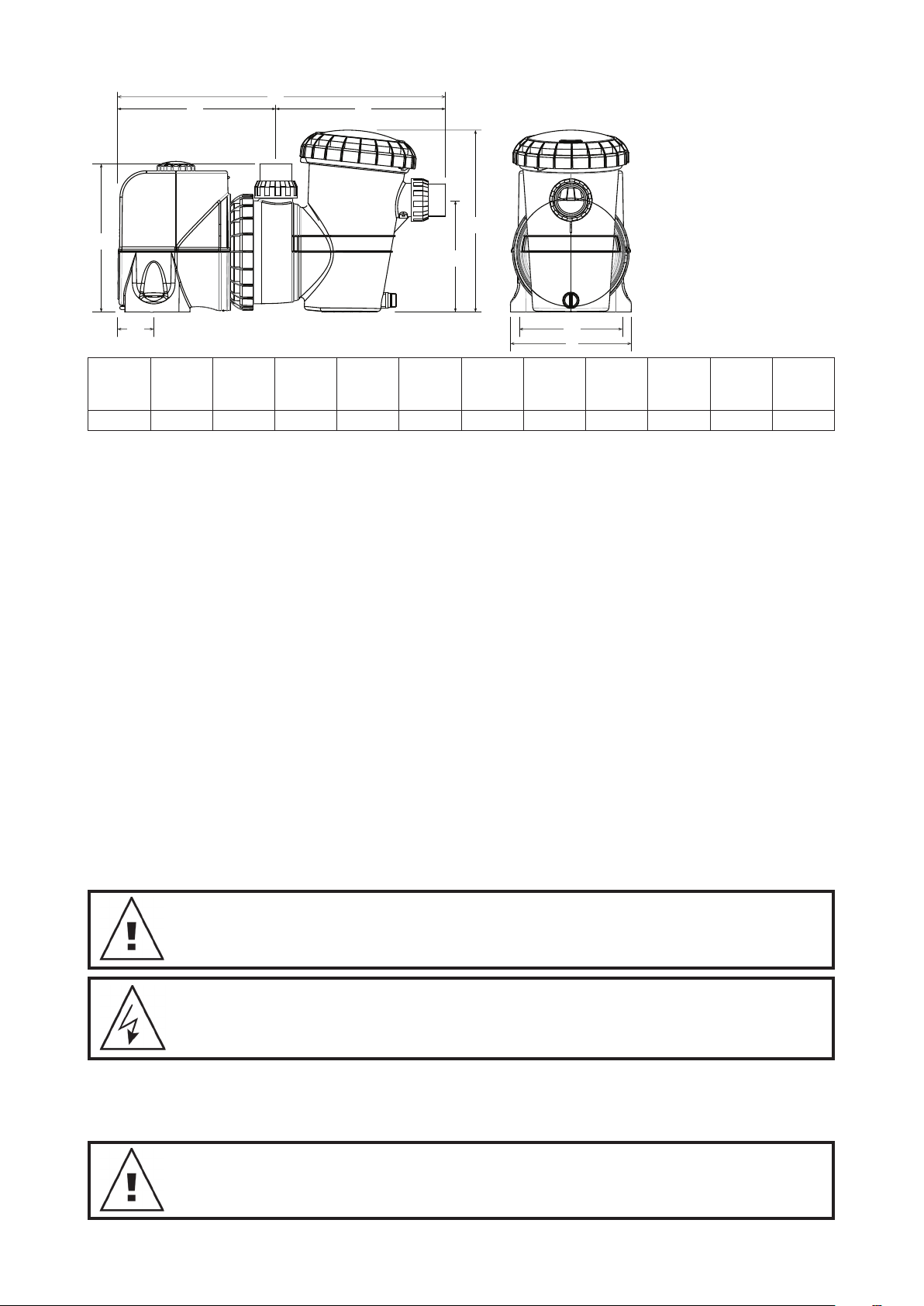
C
A
B
D
G
F
E
A
305mm 670mm 320mm 350mm 65mm 230mm 380mm 200mm 250mm 10mm 50/63 14
9.
UTILIZAÇÃO DA SUA SILENSORPRO COM UM CLORADOR DE ÁGUA SALGADA
B C
D E F G H I
H
I
Diâmetro
dos
Orifícios de
Montagem
Entrada/
Saída
PVC
Peso líquido
(kg)
Os cloradores requerem um caudal mínimo através da célula do clorador para aumentar a eficácia e a vida
da célula. Por favor, consulte o manual do clorador como referência para ver o caudal necessário ao sistema
da sua piscina. Certifique-se de que o caudal é suficiente para cobrir completamente as placas da célula do
seu clorador durante toda a operação.
10. UTILIZAÇÃO DO ASPIRADOR DA PISCINA
Antes de instalar ou comprar um dispositivo de limpeza da piscina para utilizar com a sua SilensorPRO, é
importante saber os caudais mínimos de que ele necessita para funcionar eficientemente.
Para utilizar um aspirador de piscina:
• Ative a definição de Caudal Alto (10) e permita que a bomba efetue a preparação completa, deixando-a
funcionar durante cerca de 2 minutos. Saberá que a bomba está preparada quando conseguir ver um forte
caudal de água através da tampa transparente do filtro de folhas.
• Quando todo o ar for expelido do cesto de folhas, ligue a mangueira do aspirador da piscina firmemente à
placa do skimmer ou dispositivo de sucção dedicado na parede.
• Selecione a definição de velocidade que permita o melhor desempenho do seu aspirador de piscina. As
velocidades 3 a 7 devem ser amplas o suficiente para a maioria dos aspiradores mas, se o aspirador exigir
um melhor desempenho, selecione as velocidades 7 a 10.
• O aspirador só deve ser ligado enquanto for necessário para limpar a superfície da piscina. Quando a
limpeza estiver concluída, desligue o aspirador e remova a paca do skimmer da respetiva caixa.
• Reative a definição de velocidade mais eficiente para a filtragem diária. São recomendáveis as
velocidades entre 1 e 4.
NOTA: Para obter a máxima ecácia energética da sua SilensorPRO, NÃO mantenha o
aspirador da piscina ligado quando não for necessário limpar a piscina.
NOTA: Se a SilensorPRO estiver ligada por os a um temporizador ou a outro controlo
automático, os os devem ser removidos por um técnico qualicado.
• Feche as válvulas de água no tubo de retorno da piscina e na canalização de entrada da SilensorPRO;
• Remova os conetores cilíndricos de descarga e sucção, tendo o cuidado de não perder os O-rings.
• Mova a canalização com os conetores cilíndricos ligados até a SilensoPRO poder ser puxada sem esforço.
NOTA: Quando expuser as suas dúvidas acerca da sua SilensorPRO, não se esqueça
de referir o número do modelo inscrito na placa identicativa localizada no motor.
Inglês
97
Page 98
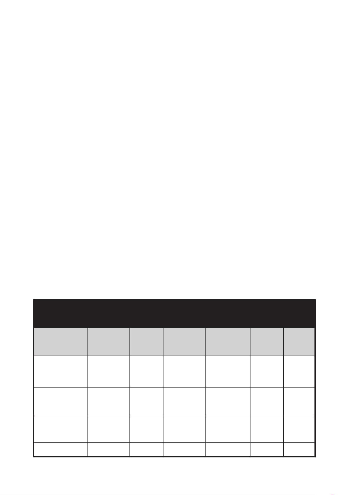
11. RESOLUÇÃO DE PROBLEMAS
Se a bomba funcionar, mas não existir caudal de água, ou existir um caudal reduzido, podem aplicarse as seguintes condições:
• O filtro requer uma retrolavagem ou está bloqueado. Consulte a secção relevante do Manual do Filtro.
• A bomba não foi preparada. Volte a preparar a bomba conforme as instruções da secção ‘Arranque da
bomba’;
• Existem fugas de ar na tubagem de sucção. Verifique todas as tubagens e elimine as fugas, verificando
também se existe alguma tampa do cesto do filtro solta. Bolhas de ar no caudal de água que volta para a
piscina indicariam uma fuga na sucção para a bomba, permitindo a entrada de ar na canalização.
• Uma fuga no vedante do eixo da bomba também pode impedir a operação. Uma evidência desta situação
seria água no chão debaixo da bomba.
• A bomba não consegue extrair água da piscina. Verifique se as válvulas para a bomba estão totalmente
abertas e se o nível de água da piscina chega à caixa do skimmer. Normalmente, é suficiente quando
atinge metade da face da caixa do skimmer;
• Bloqueio na tubagem ou na bomba. Remova o cesto do filtro e verifique se existe algum bloqueio na
entrada da turbina da bomba Verifique se existe algum bloqueio na caixa do skimmer.
Se a bomba não funcionar, podem aplicar-se as seguintes condições:
• A alimentação não está ligada. Apenas para 220-240 volts, verifique a tomada de corrente ligando um
aparelho portátil, para garantir que a alimentação está disponível. Verifique também os fusíveis e o
interruptor da fonte de alimentação principal;
• A sobrecarga automática disparou. A bomba tem uma sobrecarga térmica integrada, que é
automaticamente redefinida após o motor ter arrefecido a seguir a um período de sobreaquecimento.
Determine a causa do disparo da sobrecarga e retifique. Redefina a bomba desligando a alimentação
durante 30 segundos;
• Um bloqueio está a impedir a bomba de rodar.
12. REMOÇÃO DA SILENSORPRO DA CANALIZAÇÃO
Caso seja necessário remover a SilensorPRO, siga estas instruções:
• Desligue a alimentação e remova a ficha da fonte de alimentação;
• Desaparafuse o conetor cilíndrico da parte frontal e superior da bomba, libertando-a da canalização;
• Retire a bomba, fazendo-a deslizar da posição original.
13. QUALIDADE DA ÁGUA
COMPOSIÇÃO QUÍMICA RECOMENDADA DA ÁGUA PISCINA
ÁGUA DA PISCINA
EQUILÍBRIO
Leitura / Alcance
Ideal
Para Aumentar
Para Reduzir
Frequência dos
Testes
Cloro Livre
(ppm)
1 – 3
Aumentar a saída
do clorador.
Adicionar cloro.
Aumentar o tempo
de ltragem.
Semanal Semanal Semanal Semanal Regularmente Regularmente
pH
Piscinas
de Betão e
Mosaicos:
7,4-7,6
Outras
Superfícies:
7,2-7,4
Adicionar um
tampão ou
Carbonato de
Sódio
Adicionar Ácido
Muriático
Alcalinidade Total
TA
(ppm)
Piscina de Betão e
Mosaicos – 80-120.
Outras Superfícies
–
125-150
Adicionar
Bicarbonato de
Sódio
Adicionar Ácido
Muriático
ou Ácido Seco
Dureza do Cálcio
(ppm)
Piscina de Betão e
Mosaicos – 200-275.
Outras Superfícies –
100-225
Adicionar Cloreto de
Cálcio
Drenar parcialmente
e encher de novo a
piscina com água de
dureza inferior para
diluir
Estabilizador
– Ácido
Cianúrico
(ppm)
25 – 50 4500 – 6000
Adicionar Ácido
Cianúrico
Drenar
parcialmente e
encher de novo
a piscina para
diluir
Nível Ideal
Adicionar Sal
parcialmente
e encher de
novo a piscina
para diluir
de Sal
(ppm)
Drenar
98
Inglês
Page 99
Tarefas de Manutenção rotineiras – a m de maximizar a vida do seu equipamento
para piscina & a segurança pessoal, utilize esta lista de controlo uma vez por semana.
Primeiro, desligue a bomba.
a. Certique-se de que os manómetros estão a funcionar devidamente e que a pressão
operacional se encontra dentro dos limites conforme especicados no produto.
b. Certique-se de que cada entrada de sucção e o dreno principal têm uma cobertura
que está rmemente ligada e em condições de funcionamento seguras.
c. Certique-se de que todas as coberturas dos skimmers estão rmemente ligadas e
em condições de funcionamento seguras. Estas devem ser substituídas de 3 em 3 ou
de 4 em 4 anos.
d. Remova quaisquer obstruções ou detritos da cobertura do dreno principal.
e. Certique-se de que os cestos dos skimmers e os recipientes para cabelos e lixo da
bomba estão livres de folhas e detritos, pelo menos, uma vez por semana.
f. Remova quaisquer obstruções e materiais combustíveis que possam existir em redor
do motor da bomba.
g. Certique-se de que todas as ligações elétricas estão limpas e que todos os cabos
e equipamentos elétricos estão em boas condições. As ligações danicadas devem
ser reparadas ou substituídas por um eletricista credenciado logo que os danos
sejam detetados.
h. Verique o equilíbrio da água e os níveis do desinfetante na sua loja local de
produtos para piscina.
AS LIGAÇÕES ELÉTRICAS E A CABLAGEM DEVEM SER LEVADAS A CABO POR UM
ELETRICISTA AUTORIZADO.
PERIGO Sucção perigosa. Não bloqueie a entrada de água no sistema de ltragem om
nenhuma parte do corpo, já que a pressão pode prender cabelos ou outras partes do
copo, podendo causar ferimentos graves ou a morte. Não bloqueie a sucção.
Desligue imediatamente a bomba se alguém car preso.
Não utilize, nem ponha a funcionar, piscinas, spas ou jacuzzis, se faltar uma cobertura
de sucção ou se estiver quebrada ou solta. Têm de ser fornecidas duas coberturas e
entradas de sucção para cada bomba, para se evitar o apresamento por sucção.
De acordo com a norma AS/NZS60335.2.41, somos obrigados a informá-lo de que
este dispositivo não deve ser utilizado por crianças ou pessoas doentes, nem como
brinquedo por crianças.
Precaução! Não adicione químicos diretamente ao skimmer da piscina. A adição de
químicos não diluídos pode danicar a bomba e o ltro e anular a garantia.
99
Inglês
Page 100

Garantia da Davey
Os Davey Water Products são fornecidos com garantias que não podem ser excluídas ao abrigo da Leis nacionais
locais. Tem direito a receber uma peça de substituição ou um reembolso em caso de falha grave e uma indemnização
por qualquer outra perda ou dano razoavelmente previsível. Também tem direito a solicitar a reparação ou substituição
dos produtos caso não tenham uma qualidade aceitável e a falha não seja muito grave.
A Davey Water Products Pty Ltd (Davey) de 6 Lakeview Drive Scoresby VIC 3179 fornece a seguinte garantia
relativamente a este produto. A Davey garante que, nos termos das exclusões e limitações a seguir, o produto está
isento de defeitos de material e mão-de-obra durante um período de 24 meses a partir da data de compra (período de
garantia).
Se surgir um defeito no produto antes do fim do período de garantia e a Davey considerar que o produto tem um
defeito de material ou mão-de-obra, a Davey pode tomar uma das seguintes medidas, ao seu exclusivo critério:
1. substituir ou reparar o produto ou a peça com defeito do produto sem quaisquer encargos; ou
2. enviar o produto ou a peça com defeito do produto para reparação ou substituição por um técnico de reparação
qualificado sem quaisquer encargos.
A Davey reserva-se o direito de substituir peças com defeito do produto por peças ou componentes de qualidade, nível
e composição semelhante quando não estiver disponível uma peça ou componente idêntico. Os produtos enviados
para reparação podem ser substituídos por produtos restaurados do mesmo tipo em vez de reparados.
Reivindicação da garantia:
1. Se ocorrer uma falha abrangida pela garantia, a Davey sugere, em primeiro lugar, que contacte o Representante
Davey ao qual comprou o produto. Como alternativa, pode: ligar para a linha de Atendimento ao Cliente da Davey,
para o número 1300 367 866 na Austrália, ou 0800 654 333 na Nova Zelândia; enviar uma carta por escrito à Davey
para o endereço indicado em cima; ou envie um email para sales@davey.com.au.
2. Qualquer reivindicação da garantia deve ser acompanhada por uma prova de compra e pelos detalhes do
defeito alegado.
3. Após a receção da sua queixa, a Davey procurará resolver as suas dificuldades ou, caso o produto tenha uma
avaria o defeito, aconselhá-lo sobre como solicitar a reparação do seu produto ou obter uma substituição ou o
reembolso do valor.
4. Esta garantia limita-se aos defeitos nos materiais ou mão-de-obra no produto e não abrange peças consumíveis ou
a substituição de peças devido a um uso e desgaste normais.
Exclusões:
A garantia não se aplica quando:
O Produto tenha sido modificado, reparado ou assistido por qualquer pessoa não pertencente à Davey ou por um
1.
técnico de reparação não autorizado.
2. A Davey não consiga detetar nenhuma falha no produto após testá-lo.
3. O produto tenha sido utilizado para outro fim diferente daquele a que se destina.
4. O produto tenha sido sujeito a condições anormais, quer seja de temperatura, água, humidade, pressão, tensão ou
semelhante.
5. O comprador tenha utilizado ou instalado peças e acessórios não genuínos ou não aprovados.
6. O defeito do Produto tenha surgido devido a utilização abusiva, incorreta, negligente ou acidental.
7. O defeito do Produto tenha surgido devido a falha do comprador em utilizar ou manter devidamente o produto.
8. O dano tenha sido causado pela utilização de produtos químicos e detergentes não aprovados pela Davey.
Caso o seu produto Davey requeira reparação ou assistência após o período de garantia, por favor, contacte o seu
Representante Davey mais próximo, ou ligue ou envie um email para o Centro de Assistência a Clientes da Davey.
Para obter uma lista completa dos Representantes Davey, visite o nosso website.
INTERNACIONAL
Sede na Austrália
Ph: +613 9730 9124
Fax: +613 9753 4248
Email: export@davey.com.au
Davey Water Products Pty Ltd
Member of the GUD Group
ABN 18 066 327 517
AUSTRÁLIA
Sede
6 Lakeview Drive,
Scoresby, Australia 3179
Ph: 1300 232 839
Fax: 1300 369 119
Email: sales@davey.com.au
Website: davey.com.au
® Davey is a trademark of Davey Water Products Pty Ltd. © Davey Water Products Pty Ltd 2019.
Website: davey.com.au
EUROPA
ZAC des Gaulnes
355 Avenue Henri Schneider
69330 Meyzieu, France
Ph: +33 (0) 4 72 13 95 07
Fax: +33 (0) 4 72 33 64 57
Email: info@daveyeurope.eu
Website: daveyeurope.eu
NOVA ZELÂNDIA
7 Rockridge Avenue,
Penrose, Auckland 1061
Ph: 0800 654 333
Fax: 0800 654 334
Email: sales@dwp.co.nz
Website: daveynz.co.nz
AMÉRICA DO NORTE
Ph: +1 866 328 7867
Email: export@davey.com.au
Website: daveyusa.com
MÉDIO ORIENTE
Ph: +971 50 6368764
Fax: +971 6 5730472
Email: info@daveyuae.com
Website: daveyuae.com
100
P/N 403308-1
 Loading...