

Page 1
Silensor Pool Pump
SERVICING INSTRUCTIONS
Page 2

2
Warning!
Warning!
• All work should only be carried out by qualied persons.
• Davey products recommend that all installations are tted with earth
leakage or residual current protection devices.
• The ttings on this product are constructed of ABS. Some PVC
jointing compounds are incompatible with ABS - check suitability
before use.
• Barrel unions need to be hand tightened. No sealant, glues, or
silicones are required.
For all other trouble shooting and warnings please refer to the Silensor
installation and operating instructions supplied with each pump or contact
the Davey customer service centre on 1300 2 DAVEY (1300 232 839).
Page 3

Tools Required
Tools Required
Ring spanner 13mm
Davey Small Silensor spanner - Part number 13810-1SP
Davey Large Silensor spanner - Part number 13810SP
Davey bearing tools - Part number 48678
Davey Silensor bearing tool - Part number 48678-6
Bearing Press
Soft head mallet
Flat blade screwdriver (6mm - 12mm blade)
Allen key 10mm
Heat gun
3
Page 4
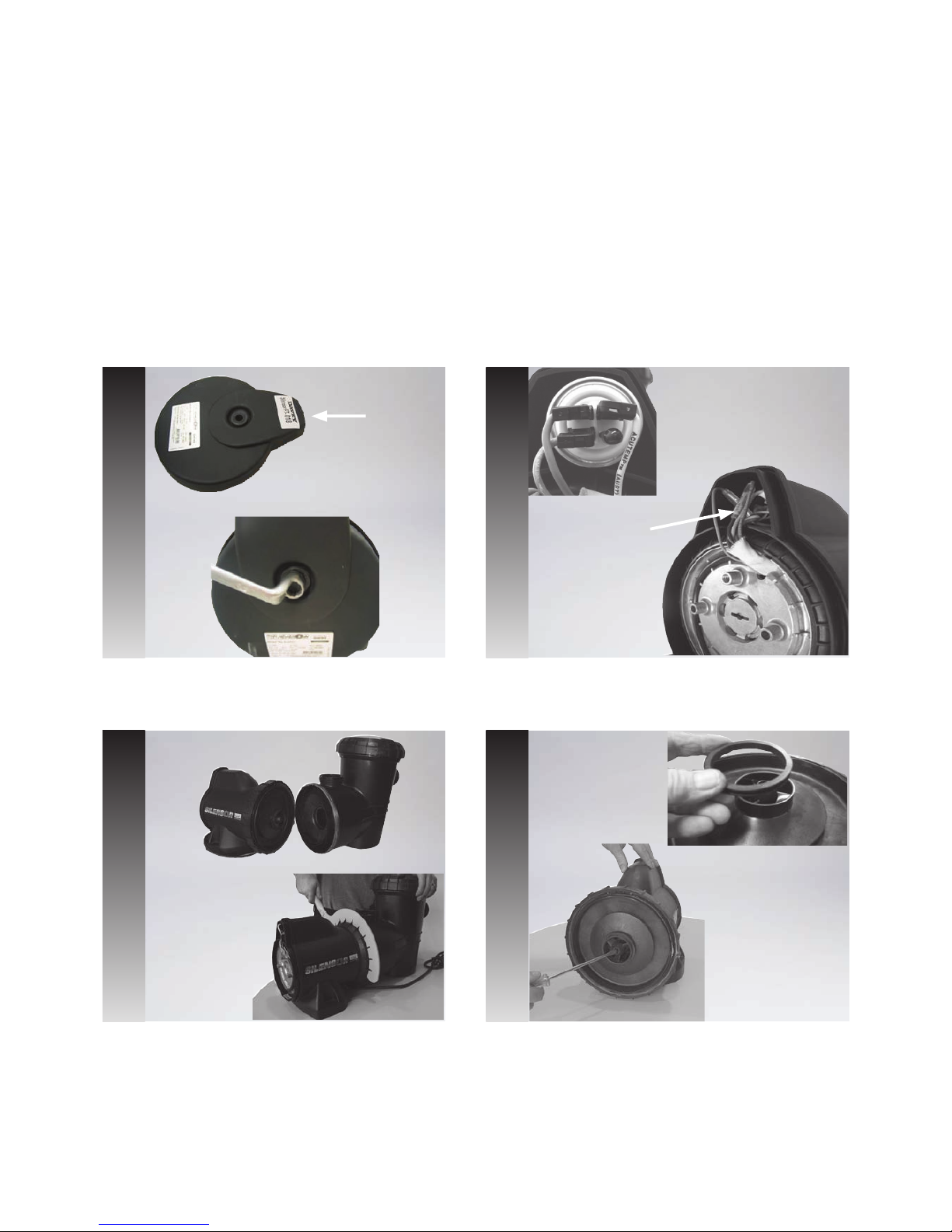
Note Wiring
Position
Capacitor Housing
Unscrew the bolt from the rear cover using a ring spanner
(13mm) and remove the cover. Note that it has a gasket
on the inside. Check for damage and replace if necessary.
Remove the capacitor from its housing. Take note of the
connections and then remove from motor.
Warning! Care should be taken when handling capacitors.
Remove the oating neck ring from the impeller and with
a at blade screw driver break the plastic tab blocking the
impeller nut.
1. 2.
4.
Tap the pump foot towards the rear with a soft head
mallet. This makes it easier to unscrew the locking nut
using the large Silensor spanner (part 13810SP). If the
spanner is tight hit the spanner with a sharp tap of the
mallet to free up the nut.
3.
4
Disassembly
Procedure
Disassembly
Procedure
Rear Cover
Page 5

5
Balance
Drum Ring
Mechanical
Seal
Hold the front of the motor and gently tap the foot to slide
off the outer casing and expose the rubber bafe.
7.
8.
9. 10.
Using a at blade screwdriver in the slot at the rear of the
motor to hold the rotor steady and an Allen key (10mm) in
the impeller nut unscrew the impeller in an anti-clockwise
direction.
5.
The rubber bafe can be removed by peeling it off from
the split on the underside of the motor.
With the small Silensor spanner (Part 13810-1SP) undo
the locking nut at the rear of the motor and remove. You
might have to hit the spanner with a sharp tap of the
mallet to free up the nut.
Remove the power lead from the non drive end shield,
then tap the motor shaft with a soft head mallet to remove
the stator assembly from the casing.
Remove the mechanical seal & Myler Washer located
beneath the mechanical seal from the impeller. If the
unit is tted with a balance drum ring then remove it and
discard as it is no longer required. This was tted up to
serial number 07078-8046.
6.
Myler
Washer
Page 6

To remove the rotor and perform a bearing change
remove the slinger, O-ring and the front sealing ring in
that order.
With a heat gun, heat this area turning the stator shell so
as not to blister the paint. After approximately 2 minutes
you should be able to tap out the rotor or push it out using
the bearing press.
Remove both bearings from the rotor but only replace the
non drive end bearing.
With the aid of the new bearing tool place the other
bearing on top and place the tool under the bearing press.
12.
13.
14.
15.
Slide the stator and shell down over the bearing tool and
press it down until the bearing is seated correctly in the
stator shell.
16.
11.
Tap off the non drive end shield taking care not to damage
the wiring. Move the power cord out of its recess to a safe
position before proceeding to the next step.
Slinger
O-ring
Sealing Ring
6
Page 7

Remove the stator and shell and turn upside down on the
small bearing tool then place back under the press. Insert
the rotor being careful of the windings and then press it
into the bearing with the press.
17.
Replace the front sealing ring, O-ring, and slinger. The
motor is now ready for reassembly.
The diffuser should be inside the front casing simply pull it
out and check for distortion and also check the O-ring that
is on the inside.
18.
19.
Note: The SLS front casing has a removable rubber ap
valve, the SLL has not.
20.
7
Page 8

Fit the O-ring to the casing and then insert the
assembled stator and rotor into it with the motor leads at
approximately 1 o’clock to the slot at the bottom of the
casing.
Place the motor shaft down through a hole in the work
bench and stand the unit on end. Next replace the end
shield by bringing the stator wires through the slot in the
end shield while the other slot should line up with the cut
out in the casing.
Bring the power lead out through the bottom slot and
push it into the cut out in the casing thread now you
can replace the casing nut and tighten it with the small
Silensor spanner (part 13810-1SP).
Replace the large case nut and bring the power lead
through it .
1.
2.
3. 4.
8
Note: It is a good idea to
have a hole in the work
bench to be able to stand
all motors on end.
O-ring
Re-assembly
Procedure
Re-assembly
Procedure
Page 9

Replace the rubber cover with the anged end down
and lock it into the slot in the casing with the power lead
running down the middle.
Slide the outer cover down over the assembly so that the
slot lines up with the slot in the casing and the power lead
comes through.
Place the mechanical seal back into position on the
impeller ensuring that the Myler Washer is located
beneath it.
Stand the assembly on its foot. Use a single drop of
Loctite 401 on the shaft, secure the shaft with a at
blade screw driver at the non drive end and screw on the
impeller by hand or with the aid of a 10mm Allen key in a
clockwise rotation. Do not over tighten.
Fit the diffuser complete with O-ring into the front casing
with the lug on the diffuser at the top.
5. 6.
7.
9.
10.
9
Replace the oating neck ring on to the impeller and also
t the casing O-ring.
Myler
Washer
Mechanical
Seal
8.
Page 10

12.
13.
10
Use the large spanner to tighten the nut. Be aware that
there is a lug on the nut that should not nish at the top
as it can interfere with the barrel union on the SLS model
Tuck all wires into the capacitor cover and then t the rear
cover complete with gasket and tighten the bolt using a
ring spanner (13mm). The pump is now ready for water
testing.
With the pump facing you place the front casing against it
and turn the casing nut anti clockwise to lock it in. There
are two slots in the motor casing that the front casing
locks into.
11.
Page 11

11
NO. DESCRIPTION PART NO.
Service motor - 75mm SLS100/150/200, SLL150 S75SM
Service motor - 83mm SLL200, SLS300/SLL300 S83SM
Service motor - 92mm SLL400 S92SM
1 Rear cover screw kit 32356
2 Rear cover - Silensor 13619SP
3 Oring - front & rear casing 44858
4 Outer cover - Silensor 13622
5 Motor cover rubber 13650
6 Case nut - large SLS requires 1, SLL requires 2 13441
7 Case nut - small SLS requires 2, SLL requires 1 12845-10~
8 Endshield - Silensor 13437
9 Oring 43069
10 Stator & shell 83mm SLL200, SLS300/SLL300 32354
10 Stator & shell 92mm SLL400 32355
10 Stator & shell 75mm SLS100/150/200, SLL150 32353
11 Front seal ring 12848
12 Oring - front seal ring 40001
13 Fan - Silensor 13564
14 Motor shell - water jacket 13443
15 Seal - mechanical 5/8” 49771~
16 Drum balance 13610
17 Impeller assy - SLL400 32364
17 Impeller assy - SLS/SLL150 32361
17 Impeller assy - SLS/SLL200 32362
17 Impeller assy - SLS/SLL300 32363
17 Impeller assy - SLS100 32360
18 Floating neckring 13569
19 Diffuser 13438
20 Oring - casing 43784
21 Bearing - 6203-2RS1/C3Wt 48997~
22 Rotor - 83mm 1ph SLL200, SLS300/SLL300 32232
22 Rotor - 92mm 1ph SLL400 32260
22 Rotor - 75mm 1ph SLS100/150/200, SLL150 32278
23 Plug & oring - priming 8890-2SP~
24 Casing front - SLL 13439
24 Casing front - SLS 13618
25 Strainer basket SLL 13562
25 Strainer basket SLS / PACR / PA / XB 11341-10~
26 Oring - leaf basket SLL 400446
26 Oring - leaf basket SLS 400445
27 Lid - SLL 13563
27 Lid - SLS 13620
28 Barrel union assy - 50mm All SLL exclud. SLL150 48722
28 Barrel union assy - 40/50mm SLL150 only 48773
28 Barrel union assy SLS models 48649
29 Flap valve - SLS only 13621
30 Lead & 3pin plug 3mts 43233-50~
Capacitor - 12mfd SLS100,150,200 & SLL150 400270~
Capacitor 25mfd SLS300 & SLL200,300,400 400655
Washer - Myler pk 10 Not Illustrated 13846*10~
Lid assy - SLL series 32429
Lid assy - SLS series 32428
Spanner - silensor large 13810SP
Spanner - silensor small 13810-1SP
Spare Parts
Spare Parts
Notes: A. Lid assembly comprises of items 6/7, 26 & 27.
B. Item 16 (balance drum - p/n 13610) is no longer used. Pumps manufactured up to serial number 07078-8046 were fitted
with balance drums. The balance drum must be removed and the alternative arrangement utilising a Myler washer (p/n
13846*10) must be fitted during re-assembly.
For further information please refer to service bulletin SP61/1550/1207.
C. Silensor service tools 13810SP & 13810-1SP required to remove case nuts during servicing.
NO. DESCRIPTION PART NO.
Page 12

SI41a/1210/WEB supersedes SI41-1/0210
Note:
Product specications may change without notice.
Drawings are indicative only, product appearance may change slightly.
® Davey is a registered trade mark of Davey Water Products Pty Ltd.
© Davey Water Products Pty Ltd 2010.
Davey Water Products Pty Ltd
Member of the GUD Group
ABN 18 066 327 517
AUSTRALIA
Head Office and Manufacturing
6 Lakeview Drive,
Scoresby, Australia 3179
Ph: +61 3 9730 9222
Fax: +61 3 9753 4100
Website: davey.com.au
Customer Service Centre
Ph: 1300 2 DAVEY (1300 232 839)
Fax: 1300 369 119
E-mail: sales@davey.com.au
NEW ZEALAND
7 Rockridge Avenue,
Penrose, Auckland 1061
Ph: +64 9 570 9135
Fax: +64 9 527 7654
E-mail: sales@daveynz.co.nz
Website: daveynz.co.nz
Customer Service Centre
Ph: 0800 654 333
REST OF WORLD
6 Lakeview Drive,
Scoresby, Australia 3179
Ph: +61 3 9730 9121
Fax: +61 3 9753 4248
E-mail: export@davey.com.au
Website: davey.com.au
Quality
ISO 9001
H/O & MF G SCORE SBY
Environment
ISO 14001
H/O & MF G SCORE SBY
 Loading...