

Page 1
Evolver Operation Manual
Page 2

2
Page 3

Evolver Operation Manual
Dave Smith Instruments
1210 Cabrillo Hwy N
Half Moon Bay, CA 94019-1449
© 2003-2010 Dave Smith Instruments
www.DaveSmithInstruments.com
Version 3.2a
July, 2010
USA
3
Page 4

y
Tested To Compl
With FCC Standards
FOR OFFICE USE
This device complies with Part 15 of the FCC Rules. Operation is subject to the
following two conditions: (1) This device may not cause harmful interference and
(2) this device must accept any interference received, including interference that
may cause undesired operation.
This Class B digital apparatus meets all requirements of the Canadian InterferenceCausing Equipment Regulations.
Cet appareil numerique de la classe B respecte toutes les exigences du Reglement
sur le materiel brouilleur du Canada.
For Technical Support, E-mail to:support@davesmithinstruments.com
4
Page 5

Contents
Quick Start 6
Basic Operation FAQs 11
Inside Evolver 12
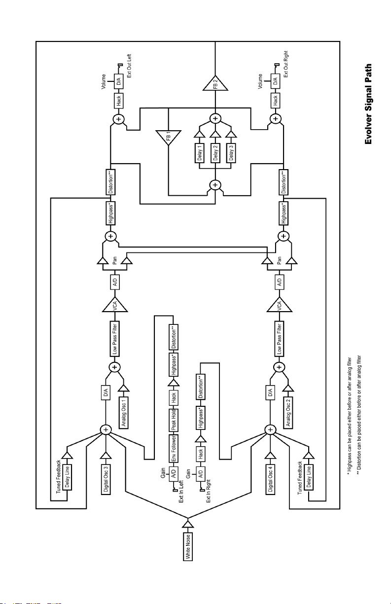
Signal Flow Diagram 13
Main Parameters 14 Main Row 1 14 Main Row 2 16
Sequencer Operation 18
Program Parameters 21 Oscillator 1 21 Oscillator 2 22 Oscillator 3 24 Oscillator 4 25 Lowpass Filter 26 Highpass Filter 27 Amplifier (VCA) 27 Feedback 28 Delay 28
Low Frequency Oscillators (LFO) 30
Envelope 3 31
Miscellaneous Audio Parameters 32
Trigger and Interface Parameters 33
Miscellaneous Timing Parameters 34
Miscellaneous Modulation Parameters 35
Modulation Destination Table 38
Modulation Source Table 40
MIDI Implementation 41
MIDI Parameters 41
Basic MIDI Messages 44
System exclusive Messages 47
Main Parameter Data 53
Program Parameter Data 54
5
Page 6

Welcome…
Thanks for purchasing Evolver! Listen to the sounds, twiddle some knobs, have
some fun!
Register
If you purchased Evolver directly from us, there is no need to register – we
already have your contact information. If you purchased Evolver from a music
dealer, please go to www.davesmithinstruments.com and register.
Version 3.0 Notes
Your Evolver has the latest 3.0 features installed. Older Evolvers can be updated
– check on our website for more information.
These features were added in such a way to have no effect on programs made
on earlier Evolvers for backwards compatibility. This means that in some cases
parameters may not be in a logical order, or additional functions were added by
increasing values at the end of their range.
Quick Start
If you are like me, you’ve already been playing with Evolver for a while, and later
decided to check the manual. If not, here’s the standard short manual to get
started.
First, plug in the power supply. If you need to use one of the alternate AC prongs,
first remove the installed prongs by pushing the button and sliding off the prongs.
Then slide on the desired prongs, and you’re ready to go.
Next, plug Evolver’s signal outputs to your mixer/sound system.
Hit the S
Programs by turning the Program knob (top Main LED must be on), and keep the
sequencer running if you want. When shipped, Bank 1 has sequencer-oriented
Programs in locations 1 through 69. A complete description of Evolver’s 512
Programs can be found in the Program Notes section following.
You can play around with the sounds of the current Program by simply selecting
a parameter in the programming matrix. Example – hit the button to select the
third row, and grab knob 1 to adjust the Filter Cutoff Frequency. Note that you
can access eight knobs in the selected row for fast tweaking. To get to the
second (lower) set of parameters in any row, simply hold the SHIFT button down
while turning the knob.
To edit the sequence steps, hit the
now changes to sequencer mode to adjust the 16 x 4 sequencer. Row 1 controls
steps 1 – 8 and row 2 steps 9 – 16 for Sequence 1. Likewise rows 3 and 4
control sequence 2, etc. The S
TART button in the lower left corner to play a sequence. Listen to other
SEQUENCER button. The programming matrix
HIFT button has no effect in sequence mode.
6
Page 7

Note - though the sequences are named 1-4, there is really only one
sequence that has four different controls, each of which can be routed to a
different destination via the four Sequence Destination parameters (bottom
left corner). In other words, one sequencer with four individual outputs that
act in parallel. Each of the four can be a different length. Sequence 1 (rows 1
and 2) controls whether a step acts as a rest (by not triggering the
envelopes). Check page 18 for more information on the sequencer.
Using Evolver with a MIDI Keyboard
Evolver is quite often used without a keyboard, just using the internal sequencer.
Other times, it is used solely from a keyboard. It can also be used in combination,
with the keyboard gating the sequencer, for example. To accommodate these
different uses, there are a couple Program parameters to select triggering modes
and oscillator frequency ranges.
The Trigger Select parameter selects the source for triggering the envelopes. It is
usually set to
Key Off/Transpose parameter provides an easy way to turn off the MIDI notes for
use with the sequencer only. So, to use a MIDI source, you must make sure this
parameter is not off! The same parameter provides MIDI transposing plus/minus
three octaves. See page 33 for more information on these two parameters.
Programs 70 through 127 in Bank 1 are sequences that are set up to play with
MIDI notes. All Programs in Bank 2 are meant to play from a keyboard, with Pitch
and Mod wheel and Pressure all enabled, and no sequences.
Note - the right decimal point in the display flashes whenever anything comes
in MIDI input jack. Note that it flashes even when MIDI input is disabled.
ALL to allow triggers from either the sequencer or from MIDI. The
Using Evolver as a Signal Processor
Simply plug your sound source into the External Inputs. If you are using a mono
signal, you will need to select single channel operation with the External Input
Mode parameter (Row 8, knob 7). You may also need to adjust the input gain –
select the second Main row by hitting the M
of gain using the Input Gain knob. Note that the row and column LEDs act as a
very simply VU meter when adjusting the gain; this helps set the optimum levels.
Ideally you want the clip LED to come on occasionally.
Usually for signal processor use, you will have the VCA Level turned up;
otherwise the signal will not get through. Other options are to use the signal to
trigger the envelopes (using Trigger Select), or using the Envelope follower
routed to VCA Level.
AIN button once, and select 0 to 24 db
Summary
You should be up and running now; for more operation information, read on. Or,
just look up specific parameters for detailed notes, or to decipher some of the
more convoluted displays. Pages 38 through 40 contain a handy reference for
mod destinations and sources. At some point you should read through the
manual to discover all the little features that you might not notice at first.
7
Page 8

I should mention that this manual does not include explanations of basic
synthesizer functions. It assumes you already know what an oscillator is, how a
lowpass filter affects the sound, what an ADSR envelope looks like, etc.
Fortunately, these days it is quite easy to find such resources on the Internet. If
you want to learn the lingo and the basics, just try a search in Google (or the
search engine of your choice), something like “analog synthesizer tutorial”. You’ll
find plenty of good reading material.
Have fun!
Dave Smith
8
Page 9

Program Notes
Following is a brief description of the 512 sounds in your Evolver. The factory sound
set is on the website if you ever need to refresh it. Remember to save your sounds via
program dumps occasionally.
Bank 1
Programs 1 – 69 are sequence programs; all you need to do is hit the S
Feel free to play around with parameters while the sequences play to get a feel of the
instrument. This group of programs is set to ignore MIDI notes coming in, i.e. they are
set at the optimum pitch and will not transpose. You can always change the
Key/OFF/Xpose parameter to enable MIDI notes if you wish (details in manual).
Programs 70 – 127 are sequences that do respond to MIDI notes. These will sound
different depending on what notes you hit on your keyboard. Many of these
sequences will be too low in pitch if you listen without a keyboard to transpose them
up. Experiment with different playing styles.
Program 128 is a test program – you’ll likely want to trash it.
Bank 2
Programs 1 – 127 are sounds meant to played from a keyboard, and have no
sequences programmed. They all respond in different ways to keyboard pressure and
mod wheel.
Program 128 is a basic keyboard program, with most parameters off. Velocity is
routed to VCA Envelope Amount, pressure goes to the filter, mod wheel goes to LFO
1 Amount, with LFO 1 controlling Oscillator Frequency. This can be handy as a
starting point, without having to worry about obscure parameters being set. On the
other hand, at first you may find it easier to make new programs by editing existing
Programs.
Bank 3
Programs 1 – 19 are droning sounds; they always play while selected. A couple have
simple sequences that alter the playback to varying degrees.
Programs 20 – 29 are signal processing programs meant to be used with a guitar
plugged into the Left Input jack. Or, any mono audio source can be used, but with
liberal use of distortion, they lean heavily towards guitar use.
Programs 30-39 are signal processing programs meant to be used with stereo audio
inputs plugged into the Left and Right Input jacks. Try playing a CD through Evolver
with these programs.
Programs 40 - 79 are an assortment of sequence sounds. Some will respond to a
MIDI keyboard, some will not.
TART button.
9
Page 10

Programs 80 - 127 are more sounds meant to played from a keyboard, and have no
sequences programmed. They all respond in different ways to keyboard pressure and
mod wheel.
Program 128 is a test program – you’ll likely want to trash it.
Bank 4
Programs 1 – 79 are a newer set of sequence programs; all you need to do is hit the
TART button.
S
Programs 80 – 128 are sounds meant to played from a keyboard; some have sequences programmed, and some do not. Most respond in different ways to keyboard pressure and mod wheel.
Special thanks to Program contributors, including:
Tim Ande
Ricardo Coen
Don Gothard
Gary LaRocco
Mario Lavin
Paul Nagle
Kevin Paisley
Robert Shanks
Ravi Sharma
Saul Stokes
John Swana
Stefan Trippler
Mark Vann
Craig Wiper
10
Page 11

Basic Operation FAQs
Evolver is a very flexible instrument. While this provides a wide range of operational
possibilities, it also means that you can put Evolver into a state where it doesn’t seem
to work. Here are some hints:
1) How do I save a Program? Hold the M
blinking. Hit the button a second time, and the Program will be stored. While
blinking, you can change the Program and/or Bank to store in a different location.
2) When I play a MIDI keyboard, it triggers the envelopes but the oscillator
pitch doesn’t change. Check Key Off/Xpose (Row 7, knob 8). If it is OFF, MIDI
notes will not affect the oscillator pitch. This knob also transposes the MIDI range
by +/- 3 octaves.
3) MIDI affects the note pitch, but will not trigger the envelopes. Check Trigger
Select (Row 7, Knob 7). It must be set to ALL or miid for basic MIDI triggering. It
can also be set miDR, miS, or miSR when using MIDI and the sequencer together –
see page . 33
4) After playing on a MIDI keyboard, I change Programs and the sounds are
transposed too high. The quick fix is to hit the R
sequencer is stopped; it acts as a MIDI all-notes-off, and resets all MIDI
controllers. In general, you usually want to set up Programs as sequencer-driven,
MIDI-driven, or both. When you try to play a sequence-based Program with MIDI,
or sequence a MIDI-based sound, you will likely have to change a couple
parameters (see 1 and 2 above).
5) I hit the Sequence Start button; the LEDs advance, but the envelopes don’t
trigger. This is the opposite problem of 2 above; check Trigger Select (Row 7,
Knob 7) - it should be set to ALL or SEQ for the sequencer to trigger the
envelopes.
6) When I change Programs, the Sequencer speed always stays the same.
Check Use Prgm Tempo – if it is OFF, then the speed is not updated when
Programs change. Set it to On.
7) How do I copy Sequences from one Program to another? First, turn Lock
Seq off, and select the Program with the sequence that you want to copy.
Second, turn Lock Seq On – now when you change Programs the sequence will
not change, so select the destination Program. Third, do a normal save, and the
Sequence will be saved in the new location.
8) I can’t get the filter to oscillate. Check the 2 pole/4 pole switch (Row 3, Knob 1,
Shift) – the filter only oscillates when 4 poles are used.
9) I seem to be getting some distortion in my output. Assuming that the
Distortion is off, you are likely just overloading the signal somewhere. There are
many signal sources in Evolver, and many sources of gain. If too many are used
at levels that are too high, you will likely get some distortion. For example, if you
are using all four oscillators, you should have the levels lower, in the 40 – 60
range. Likewise, if using all three delay taps, lower the levels of each.
10) Reset Main Parameters - There is a quick reset of the Main parameters; just hit
row 1 and 4 buttons at the same time, and the Main parameters will be reinitialized.
AIN button down; its LED will start
ESET button when the
11
Page 12

Inside Evolver
Before going through the individual parameters, following is a brief description of
Evolver’s architecture. The signal flow diagram on the next page is a good starting
point for understanding how Evolver works.
The Analog Side
Evolver’s analog electronics consist of two identical (Left/Right) synth sections, each
with an analog waveshape oscillator, a 2/4 pole resonant lowpass filter, and a Voltage
Controlled Amplifier (VCA). Control voltages are generated by the processors to
control the analog components.
The Digital Side
Surrounding the Analog electronics is a high-speed Digital Signal Processor (DSP)
that both pre- and post-processes the audio signal. Since the DSP also computes the
control voltages for the analog circuitry, it can handle a wide range of modulation with
high precision.
The DSP provides audio functions such as the Digital Oscillators, Envelope Follower,
the Peak/Hold detector (and associated external trigger generator), Highpass filter,
Distortion (with noise gate), Pan, Delay, and Hack. It also handles the tuned
feedback, as well as the additional Delay feedback paths, and all the modulation
calculations (envelopes, LFOs, routing, etc).
Analog-to-Digital (A/D) and Digital-to-Analog (D/A) converters are used to connect the
analog and digital. As can be seen, there are two sets of stereo converters; they run
at 48 kHz sampling rate with 24 bits of precision for minimum impact on the analog
sound.
This architecture allows a great deal of flexibility in defining the feature set of the
synth. The analog circuitry is fixed, but all other features are software defined in
Evolver’s two processors.
12
Page 13
13
Page 14

Main Parameters
There are two rows of Main, or global, parameters. Hitting the M
will toggle between the first row and the second. All Main parameters are saved when
power is removed.
Program Save: If you hold the M
that it is ready to store a program. Hitting the M
AIN button, its LED will start blinking, which indicates
AIN button a second time will store the
program. You can change the Bank and Program number while it is blinking to move
programs between locations and banks. Hitting any other button or turning a knob
(other than Program/Bank) will stop the blinking and abort the save.
Main Row 1
1 Program: 1…128 Select Program in the currently selected bank. If you hold
the S
HIFT button while changing the Program, the sound will not change until you
release the S
the sequencer is running, when the S
complete (according to the length of Sequence 1) before synchronously changing to
the new program and it’s sequence.
2 Bank Select: 1…4 Select Bank. Each bank has 128 Programs, for a total of
512 Programs. If you hold the S
not change until you release the S
changing the Bank and the sequencer is running, when the S
the sequence will complete (according to the length of Sequence 1) before
synchronously changing to the new program and it’s sequence.
3 Volume: 0…100 Master Volume control
4 Transpose: -36…+36 Master Transpose control, 0 is centered. Steps in
semitones.
5 BPM: 30…250 Basic speed for the sequencer in BPM. Actual speed also
depends on the Clock Divide setting (see below). If using MIDI clock, it will display the
BPM of the incoming MIDI clocks.
6 Clock Div: see table Used as a clock divider to provide a wider range of
sequencer speeds. When set to 4n (quarter notes), the BPM setting is exact, i.e. 120
BPM = 120 BPM. If set to 2n (half note), the actual speed is half, so a setting of 120
BPM will actually play at 60 BPM.
Swing settings add a delay to every the odd steps (1, 3, 5, etc.), while shortening the
even steps by the same amount, for a swing feel to the timing. Half swing is the same
with less delay.
HIFT button. If you hold the SHIFT button while changing the Program and
HIFT button is released the sequence will
HIFT button while changing the Bank, the sound will
HIFT button. If you hold the SHIFT button while
AIN button repeatedly
HIFT button is released
14
Page 15

Here are all the possible settings, with the effect on the overall tempo:
Display Tempo Timing Division
2n
4n
8n
8H
8s
8t
16n
16H
16s
16t
32n
32n
64n
BPM/2 Half note
BPM Quarter note
BPM x 2 Eighth note
BPM x 2 Eighth note, half swing timing
BPM x 2 Eighth note, full swing timing
BPM x 3 Eighth note triplets
BPM x 4 Sixteenth note
BPM x 4 Sixteenth note, half swing timing
BPM x 4 Sixteenth note, full swing timing
BPM x 6 Sixteenth note triplets
BPM x 8 Thirty-second note
BPM x 12 Thirty-second note triplets
BPM x 24 Sixty-fourth note triplets
7 Use Prgm Tempo: Off, On Use Program Tempo – when set to OFF, changing
a Program will not change the tempo- this is useful for keeping a constant tempo but
using different sounds. If set to On, a Program change will change the tempo to the
BPM and Clock Divide values saved with the Program. When on, changing the main
BPM will also change the Program BPM, and vice-versa. When off, changing one has
no effect on the other.
8 MIDI Clock: see table Selects the MIDI clock status, and enables External
sequencer triggers, as follows:
Display MIDI Clock Setting
OFF
OUT
IN
I-O
in-
MIDI clock is neither sent nor received
MIDI clock is sent
MIDI clock is received
MIDI clock is received and transmitted
MIDI clock is received, but MIDI start/stop/continue
messages are ignored.
15
Page 16

Main Row 2
1 Lock Seq: Off, On When set to OFF, sequencer operation is normal, and
each Program plays its own sequence. If set to On, the sequence does not change
when changing a Program. This provides an easy way to hear the same sequence
with different sounds. Note that Lock Sequence can be used to copy a sequence from
one Program to another.
2 Poly Chain: see table Poly Chain is used to link multiple Evolvers into a
polyphonic system by selectively passing MIDI data through to the MIDI out jack
where it can be routed to another Evolver. Note that MIDI clocks are handled
separately per the MIDI Clock parameter. Settings:
Display Poly Chain Status
OFF
ALL
not
3 Input Gain: 0db… 24d Provides extra gain on the Left and Right External
Inputs. You can select no gain (0db), or a gain in steps of 3db up to 24d (24db). Note
that when the Input Gain knob is active, the row and column LEDs become a simple
VU meter, with the rows showing the left channel, and the columns showing the right.
The Clip LED is always active.
The Clip LED has a dual purpose – it lights when either the left or right External Inputs
clip, and it also lights when there is a clip on the internal A/D, which follows the analog
circuitry (see signal flow diagram on page 13). This helps set internal levels and
prevent clipping and distortion (unless of course you want it to clip/distort!).
4 Fine Tune: -50…+50 Master Fine Tune control; 0 centered. Steps in cents (50
cents = ½ semitone).
5 MIDI Rec: see table MIDI Receive – determines what MIDI data to receive.
Used to disable MIDI completely, or to filter out program changes or parameter
changes.
Display MIDI Receive Operation
OFF
ALL
pro
par
MIDI operation is normal.
All MIDI information is passed through to the MIDI out jack
Only MIDI note data is passed through to the MIDI out jack.
No MIDI data received
All MIDI data received
Only MIDI program changes received (along with
note/controller data)
Only MIDI parameters received (along with note/controller
data)
16
Page 17

6 MIDI Xmit: see table MIDI transmits – determines what MIDI data to send. If
enabled Evolver will send out changes for all 128 Program Parameters in System
Exclusive (SysEx) format – see the MIDI Implementation section starting on page 41
for more information.
Display MIDI Transmit Operation
OFF
ALL
pro
par
No MIDI data sent
All MIDI data sent
Only MIDI program changes sent
Only MIDI parameters sent
7 MIDI Channel: ALL, 1…16 Select which MIDI channel to send and receive
data, 1 to 16. ALL receives on any channel.
8 MIDI Dump: see table Allows transmission of Programs over MIDI as follows:
Display MIDI Transmit Operation
ONE
BAN
ALL
Send current program
Send all 128 programs in current bank
Send all programs in all three banks
When this knob is active, the sequencer S
TART/STOP button is hit, the transmission will start. Handy for saving Programs on a
S
TART/STOP LED will start blinking. When the
computer or sending to another Evolver. Evolver’s Program dumps include Program
and Bank numbers, so when received it will be stored in same location.
17
Page 18

Sequencer Operation
Evolver has a 4 x 16 “analog” style step sequencer. Imagine four rows of 16 knobs. It
is really a single sequencer with four controls per step, though the convention in
Evolver is to call the four rows sequence 1 through 4.
When you hit the S
light in sequence to show which step is playing; remember that each sequence is two
rows, so the LEDs repeat.
Each of the four sequences is basically a modulation source; it can be routed to any
of the normal modulation destinations (see table on page 38) using the Seq Dest
knobs (last row). Usually at least one of the sequences is routed to an oscillator to
control pitch. Using VCA Envelope as a destination allows setting the volume of each
step; likewise you can go to the Filter or Filter Envelope Amount to have different filter
settings per step.
Beyond this, you can really have some fun with other destinations; go to Delay
amount to have the delay level change; or feedback amount, to drastically change the
sound every step. FM and Ring Mod are fun to change – you get the idea. With four
sequences, you can program a very dynamic sequence.
Note – another very useful way to modulate a sequence is using LFOs with sync;
LFO frequency runs 0 – 150, after which you can select the sync settings. A
setting of S16 on an LFO with a Triangle wave selected and routed to the filter will
provide a clean filter sweep over a 16 step sequence, perfectly in sync! This is
much easier (and smoother) than programming a filter sweep using sequence
steps.
The sequencer can also be routed to MIDI output destinations, including Note
Number, Velocity, Mod Wheel, Pressure, Breath, and Foot Controller. Velocity is a
special case – it only works if selected as the destination for Sequence 2 when
Sequence 1’s destination routed to Note Number. The same for Sequence 3 and 4
(Sequence 4 can be velocity for Sequence 3). If velocity is not used as a destination,
the velocity output is 120. So, it is possible to have up to 4 note sequences sent out
over MIDI.
Another sequencer destination is Clock Mod. It works via a multiplier based on a step
value of 40. If a sequencer step is set to 40, the clock speed stays as set. If set to 20,
(half of 40), the clock will be twice as fast for that step. Likewise, a step value of 80
will be twice as slow as normal, and 10 would be 4 times faster.
Note that overall limits of 30 to 250 BPM still apply; for example, if you have a BPM of
120, and a sequencer step of 10, it will try to go four times faster than 120, which is
480. Since it is greater than 250, it will clamp at 250. With clever choices of BPM
(using Clock Divide as necessary) you can develop a pretty wide range of timing
possibilities. Also, with sequences of different lengths, it can really get quite wild.
The actual MIDI note transmitted is the sequence step value plus one (since MIDI
note on of zero = note off). Note that this is different than the half-semitone when
driving the internal oscillators – this was done to provide a wider range of notes. Also,
the main Transpose is added/subtracted to the MIDI note output. Velocity and the
other controllers are converted from 0 – 100 range to 0 – 127 range for MIDI.
TART button, the sequence will start playing. The column LEDs will
18
Page 19

To program the sequencer, hit the SEQUENCER button; the SEQUENCER LED will light
indicating that the program matrix is now active for editing the sequences. Row 1 has
positions 1-8 of Sequence 1, and Row 2 has positions 9-16 of Sequence 1. Likewise
the remaining rows cover Sequences 2 – 4.
You can easily switch the matrix back and forth between normal Program edit mode
and sequence mode by hitting the S
sequence destinations set, you can simply start a sequence (hit the S
EQUENCER button. Assuming you have the
TART/STOP
button), and hear the result as you change the sequence step values, which range
from 0 to 100.
Note - when routing a sequencer to an oscillator, a sequence value of 24
corresponds to one octave, i.e. each step is one half a semitone.
You may find it easier at first to stop the sequence before adjusting each step. On
each “click” of the knob, it will trigger the envelopes so you can hear the current
setting of the knob. Once you go through all steps, then you can start the sequence to
hear the result, and make fine tuning changes while running.
All four sequences can have separate lengths. This is done by selecting rst (at the
end of the range after 100) as the step value. When this step is reached, the
sequence will reset to step one. For example, if you want a four step sequence,
simply set step 5 to rst.
Each sequence can have its own reset, so you will need to set the reset for all four
sequences if you want all of them to be the same length. And, if each is a different
length, the rests (see below) and clock swing settings will follow sequence 1, as will
the LEDs. In other words, the envelopes are always triggered from one sequence and
can’t be separately handled by each of the 4 sequences, which makes sense on a
monophonic instrument if you think about it.
Sequence 1 (rows 1 and 2) controls rests. If set to off (after rst at the end of the
range) there will not be a trigger to the envelopes on that step. As mentioned above,
the rests will end up in different places on other sequences if they are a different
length.
Using rests, resets, and different Clock Divides (half swing, swing, etc.) you can
achieve very complex sequences.
Another method of programming of pitched sequences is via a MIDI keyboard. Hold
EQUENCER button, and its LED will start blinking, indicating that the currently
the S
selected sequence will accept key information over MIDI. Each MIDI note-on will be
saved in the current sequence location, and will automatically step to the next. It will
loop around from step 16 to 1 if you keep playing notes. MIDI notes below C2 (48) act
as rests. Note C2 will program a zero, C#2 a 2, etc.
Timing is not recorded when programmed from a keyboard; it is simply a convenience
feature for entering note values.
TART/STOP starts and stops the sequencer; the RESET button will reset the sequence
S
to step one if the sequencer is running or not running.
Note – the R
ESET button also acts as a MIDI all-notes-off, and resets all MIDI
controllers when hit while the sequencer is not running.
19
Page 20

While the sequencer is running, if you hold the S
HIFT button when you hit the STOP
button, the sequence will continue running until finished (according to the length of
Sequence 1), and will stop after playing step 1.
Also, If you hold the S
sequencer is running, when the S
HIFT button while changing the program or bank and the
HIFT button is released the sequence will complete
(according to the length of Sequence 1) before synchronously changing to the new
program and it’s sequence.
A simple “tap tempo” feature is available. With the sequencer off, hold the R
button, and then hold the S
TART/STOP button in time. The sequencer will start with the new tempo. Note – the
S
TART/STOP button for a count of four; then lift up the
ESET
actual speed will depend on the Clock Divide setting. The count will match if Clock
Divide is set to 4n. If set to 8n, it will play twice as fast as your “tap”, and so forth.
Sequences normally start when you hit the S
TART/STOP button, but some are meant
to be played as gated sequences from a keyboard. On these programs, the
TART/STOP LED will light up automatically. For more details, check the Trigger Select
S
parameter on page 33.
20
Page 21

Program Parameters
There are eight rows of Program parameters. In addition, holding the S
gives access to an additional 64 parameters. The S
ways. While held, it always selects the alternate parameter (in yellow). The selected
row LED blinks to indicate that S
button twice quickly, and now the matrix will be in shift mode – the row LED will blink,
and the alternate parameter is selected, but you do not have to hold the button down.
This is handy when tweaking while playing a keyboard with your other hand. Hit S
once more and it returns to normal.
Note - sometimes the shifted parameter is related to the unshifted parameter
above it, but other times they are unrelated. The panel artwork shows the
grouping to make it more obvious.
To select a row to edit, simply hit the desired row button, and you can turn any of the
eight knobs to change a parameter in that row.
Note - you first select a knob and turn it one click, it selects and displays the
parameter but does not change the programmed parameter value. Any further
turning will then modify the value up or down. This makes it easy to check the
value of a parameter without changing it.
The following parameter details are grouped by function, with row and column as
indicated in the boxes: 5 2 . Would be Row 5 Column 2 (the Grunge parameter, in
this case). An S denotes the SHIFT button is held down to access the parameter.
HIFT is selected. Alternatively, you can hit the SHIFT
HIFT button operates two different
Oscillator 1
Oscillator 1 is an analog oscillator, and is hardwired to the Left channel. Following are
the main controls for Oscillator 1. Note that there are some additional modulation
controls that will affect Oscillator 1 – these are found in different sections of the
Parameter definitions.
Frequency: 1 1 C…C8 Selects base frequency over a 10 octave range, from 8
Hz to 8KHz, stepping in semitones. C3 is middle C, the first octave has no number (c ,
db , d …), the second octave is –1 (c -1, db-1, d -1…), the third is zero (c 0, db0,
d 0 …), etc.
Fine: 1 2 -50…+50 Fine Tune control; 0 centered. Steps in cents (50 cents = ½
semitone).
HIFT button
HIFT
21
Page 22

Shape/PW: 1 3 see table Selects the analog waveshape as follows:
Display Waveshape
Sat
tri
s-t
p 0 to p99
Sawtooth
Triangle
Sawtooth – triangle mix
Pulse Wave, with pulse width ranging to minimum (0) to
maximum (99). The pulse width will turn off at the two
extremes – this allows some interesting modulation
possibilities. A square wave will be around P50.
Level: 1 4 0…100 Sets the volume of Oscillator 1.
Glide: 1 1 S 0…100; F02…F99; OFF The oscillator 1 Glide rate; low numbers
are faster. Normal Glide covers the range from 1 to 100 (0 is no glide). A “fingered”
mode that only glides when more than one note is held down is selected by setting
glide over 100, where it ranges from F02 to F00 (equivalent to glides of 2 to 100).
Thought not quite Glide related, if you set glide all the way to maximum, it goes to
OFF, which has the effect of disconnecting oscillator 1 from MIDI.
Sync 2->1: 1 2 S Turns oscillator hard sync on or off. Whenever oscillator 2 resets,
it will also reset oscillator 1 for the classic hard sync sound.
Oscillator 2
Oscillator 2 is also an analog oscillator, and is hardwired to the Right channel.
Following are the controls for Oscillator 2:
Frequency: 1 5 C…C8 Selects base frequency over a 10 octave range, from 8
Hz to 8KHz, stepping in semitones. C3 is middle C, the first octave has no number (c ,
db , d …), the second octave is –1 (c -1, db-1, d -1…), the third is zero (c 0, db0,
d 0 …), etc.
Fine: 1 6 -50…+50 Fine Tune control; 0 centered. Steps in cents (50 cents = ½
semitone).
22
Page 23

Shape/PW: 1 7 see table Selects the analog waveshape as follows:
Display Waveshape
Sat
tri
s-t
p 0 to p99
Sawtooth
Triangle
Sawtooth – triangle mix
Pulse Wave, with pulse width ranging to minimum (0) to
maximum (99). The pulse width will turn off at the two
extremes – this allows some interesting modulation
possibilities. A square wave will be around P50.
Level: 1 8 0…100 Sets the volume of oscillator 2.
Glide: 1 5 S 0…100; F02…F99; OFF The oscillator 2 Glide rate; low numbers
are faster. Normal Glide covers the range from 1 to 100 (0 is no glide). A “fingered”
mode that only glides when more than one note is held down is selected by setting
glide over 100, where it ranges from F02 to F00 (equivalent to glides of 2 to 100).
Thought not quite Glide related, if you set glide all the way to maximum, it goes to
OFF, which has the effect of disconnecting oscillator 3 from MIDI.
23
Page 24

Oscillator 3
Oscillator 3 is a digital waveshape oscillator, and is hardwired to the Left channel. Like
the Prophet VS, the digital oscillators in Evolver get quite trashy at higher frequencies.
Following are the controls for Oscillator 3:
Frequency: 2 1 C…C8 Selects base frequency over a 10 octave range, from 8
Hz to 8KHz, stepping in semitones. C3 is middle C, the first octave has no number (c ,
db , d …), the second octave is –1 (c -1, db-1, d -1…), the third is zero (c 0, db0,
d 0 …), etc.
Fine: 2 2 -50…+50 Fine Tune control; 0 centered. Steps in cents (50 cents = ½
semitone).
Shape/PW: 2 3 1…128 Selects a digital waveshape. Waveshapes 1 - 95
correspond to ROM (preset) Waveshapes 32 – 126 in the Prophet-VS. Waveshapes
97 – 128 are user programmable via the software editor. In the VS, the user waves
were 0 - 31, and wave 127 was noise, which is not included because the Evolver has
a separate noise generator. Wave 96 has a Waveshape that is unique to Evolver in
place of the VS noise. Wave 95 (126 on the VS) is a “blank” wave, which can give
some options while sequencing waves. The Evolver ships with waves 97 – 128 the
same as 1 – 32.
Level: 2 4 0…100 Sets the volume of oscillator 3.
Glide: 2 1 S 0…100; F02…F99; OFF The oscillator 3 Glide rate; low numbers
are faster. Normal Glide covers the range from 1 to 100 (0 is no glide). A “fingered”
mode that only glides when more than one note is held down is selected by setting
glide over 100, where it ranges from F02 to F00 (equivalent to glides of 2 to 100).
Thought not quite Glide related, if you set glide all the way to maximum, it goes to
OFF, which has the effect of disconnecting oscillator 3 from MIDI.
FM 4->3: 2 2 S 0…100 The amount of Frequency Modulation of Oscillator 3
from Oscillator 4. Note that each digital oscillator can FM the other at the same time
for some wild results.
Shape Seq: 2 3 S Off, SE1..4 This parameter allows sequencing Waveshapes.
Off if not in use, otherwise select one of the four sequences se1, se2, se3, or se4 to
change the waveshape on every sequence step. In other words, if sequence 1 is
selected, with step 1 = 10 and step 2 = 5, then waveshape 10 will play in the first step,
and waveshape 5 will play in the second.
Ring Mod 4->3 : 2 4 S 0…100 The amount of Ring (Amplitude) Modulation of
Oscillator 3 from Oscillator 4. Note that each digital oscillator can Ring modulate the
other at the same time.
24
Page 25

Oscillator 4
Oscillator 4 is a digital waveshape oscillator, and is hardwired to the Right channel.
Like the Prophet VS, the digital oscillators in Evolver get quite trashy at higher
frequencies. Following are the controls for Oscillator 4:
Frequency: 2 5 C…C8 Selects base frequency over a 10 octave range, from 8
Hz to 8KHz, stepping in semitones. C3 is middle C, the first octave has no number (c ,
db , d …), the second octave is –1 (c -1, db-1, d -1…), the third is zero (c 0, db0,
d 0 …), etc.
Fine: 2 6 -50…+50 Fine Tune control; 0 centered. Steps in cents (50 cents = ½
semitone).
Shape/PW: 2 7 1…128 Selects a digital waveshape. Waveshapes 1 - 95
correspond to ROM (preset) Waveshapes 32 – 126 in the Prophet-VS. Waveshapes
97 – 128 are user programmable via the software editor. In the VS, the user waves
were 0 - 31, and wave 127 was noise, which is not included because the Evolver has
a separate noise generator. Wave 96 has a Waveshape that is unique to Evolver in
place of the VS noise. Wave 95 (126 on the VS) is a “blank” wave, which can give
some options while sequencing waves. The Evolver ships with waves 97 – 128 the
same as 1 – 32.
Level: 2 8 0…100 Sets the volume of oscillator 4.
Glide: 2 5 S 0…100; F02…F99; OFF The oscillator 4 Glide rate; low numbers
are faster. Normal Glide covers the range from 1 to 100 (0 is no glide). A “fingered”
mode that only glides when more than one note is held down is selected by setting
glide over 100, where it ranges from F02 to F00 (equivalent to glides of 2 to 100).
Thought not quite Glide related, if you set glide all the way to maximum, it goes to
OFF, which has the effect of disconnecting oscillator 4 from MIDI.
FM 3->4: 2 6 S 0…100 The amount of Frequency Modulation of Oscillator 4
from Oscillator 3. Note that both digital oscillators can FM the other at the same time
for some wild results.
Shape Seq: 2 7 S Off, SE1..4 This parameter allows sequencing Waveshapes.
Off if not in use, otherwise select one of the four sequences se1, se2, se3, or se4 to
change the waveshape on every sequence step. In other words, if sequence 1 is
selected, with step 1 = 10 and step 2 = 5, then waveshape 10 will play in the first step,
and waveshape 5 will play in the second.
Ring Mod 3->4: 2 8 S 0…100 The amount of Ring (Amplitude) Modulation of
Oscillator 4 from Oscillator 3. Note that both digital oscillators can modulate the other
at the same time.
25
Page 26

Lowpass Filter
The analog (real analog!) lowpass filter is actually two different filters; one for the Left
channel and one for the Right channel. This allows true stereo processing of external
audio signals run through Evolver. However, for simplicity and consistency the two
filters are driven together in tandem, so they normally respond the same way.
Exceptions are when using the Spilt parameter as noted below, and when using the
separate filter cutoff and resonance modulation destinations, which allow the two
filters to be modulated independently. Note that though they are normally controlled
together, since they are analog there will always be some subtle differences between
the two filters, which gives Evolver a more natural sound.
Frequency: 3 1 0…164 Selects base filter cutoff frequency over more than 13
octaves. There is special smoothing on the operation of the filter knob to eliminate
stepping as you turn the knob for clean manual filter sweeps.
Env Amt: 3 2 -99…+99 Amount of filter envelope to the cutoff frequency. This
can be positive or negative, allowing inverted envelope control of the filter.
Attack: 3 3 0…110 Attack time of the filter ADSR envelope generator
Decay: 3 4 0…110 Decay time
Sustain: 3 5 0…100 Sustain Level
Release: 3 6 0…110 Release time
Resonance: 3 7 0…100 Sets the Resonance level of the filter; at high settings
the filter will self-oscillate in 4-pole mode. If the filter does not oscillate, make sure that
4 pole mode is selected.
Key Amt: 3 8 0…100 Amount of keyboard (MIDI note) to the filter cutoff. A
setting of 72 will step the filter one semitone for each MIDI note, 36 would be halfsemitones, etc. Also, the MIDI note is derived using Oscillator 1 Glide, allowing Glide
tracking.
2/4 Pole: 3 1 S 2 P, 4 P Selects either 2 or 4 pole operation for the filter.
Velocity: 3 2 S 0…100 Amount of MIDI velocity controlling the level of the filter
envelope.
Audio Mod: 3 3 S 0…100 Amount of audio modulation from the analog
oscillator to the filter, separate in left and right channels.
Split: 3 4 S 0…100 Split separates the cutoff of the left and right filters by
raising the left and lowering the right. Normally the filters track in both channels; this
allows a way to unlock them.
26
Page 27

Highpass Filter
Highpass: 3 5 S o0…99, i0…99 Sets the cutoff frequency of the four-pole
highpass filter. If set to o00 to o99, the filter is placed after the analog lowpass filter
and VCA, before the Delay. If set to i00 to i99, the highpass filter is inserted before
the analog lowpass filter, and only affects external input. Refer to the Signal Flow
diagram on page 13. There are two separate highpass filters, one for each channel,
that are controlled in tandem.
Remember that any of the modulation sources can be routed to the Highpass Filter;
for example Envelope 3 can be dedicated to the Highpass.
Amplifier (VCA)
VCA Level: 4 1 0…100 Sets a base level for the VCA (Voltage controlled
Amplifier). This allows the VCA to be essentially bypassed, which may be necessary
for processing external audio signals, or for Programs that drone.
Note – if VCA Level is on full, then the Envelope Amount will have no effect.
Env Amt: 4 2 0…100 Amount of VCA envelope to the VCA level.
Attack: 4 3 0…110 Attack time of the VCA ADSR envelope generator
Decay: 4 4 0…110 Decay time
Sustain: 4 5 0…100 Sustain Level
Release: 4 6 0…110 Release time
Velocity: 4 2 S 0…100 Amount of MIDI velocity controlling the level of the
VCA envelope.
Output Pan: 4 7 see table pan settings as below. This affects the feedback; it
allows signal from one channel to feedback into the other, for example.
Display Output Pan Selection
St1
St2
St3
miON
Stereo 1 – Left channel panned fully left, Right fully to the
right
Stereo 2 – Left channel panned mostly left, Right mostly to
the right
Stereo 3 – Left channel panned somewhat left, Right
somewhat to the right
Mono – Both channels mixed to the center – also useful
when only using one output
27
Page 28

rs1
rs2
rs3
Volume: 4 8 0…100 Sets the voice volume; usually used for matching volumes
between Programs.
Reverse Stereo 1 – Right channel panned somewhat left,
Left somewhat to the right
Reverse Stereo 2 – Right channel panned mostly left, Left
mostly to the right
Reverse Stereo 3 – Right channel panned fully left, Left fully
to the right
Feedback
Feedback is implemented via two identical tuned delay lines, one for each channel –
see the diagram on page 13. Since the delay is tuned, it can be played by modulating
the feedback frequency from the sequencer or other sources.
Note – Feedback can also be used to implement plucked string physical models –
use Envelope 3 with Noise as a destination (all oscillators off). Assign a sequence
to Feedback Frequency, play around with different Feedback Levels, and adjust
the filter cutoff frequency.
Frequency 5 1 0…48 Sets the base frequency of the main feedback loop. It
steps in semitones from C0 to C4 (0 – 48) for a four octave range. The exact
frequency is influenced by other factors, such as the filter frequency and number of
poles, which can drive it slightly sharp or flat.
Level 5 2 0…100 Level of feedback. As the level goes up the feedback will
eventually oscillate at the set Frequency. Medium levels of feedback add depth and
movement to the sound.
Grunge 5 3 OFF…On When on, it enables nasty feedback at higher levels –
it will not have any effect at lower levels of feedback.
Delay
The delay takes a mix of both channels as input, and provides up to three
independent taps, each which can be separately time or level modulated. The output
of the three taps is mixed and summed with the Left and Right channels. The delay
output also can be mixed back to the input of the delay for more ambience, repeating
delays, or tuned feedback if the feedback level is set high.
A second feedback path takes the delay output and routes it back to the input of the
analog filter; this path can be used for more extreme feedback effects.
28
Page 29

Note – if all three Delay taps are in use, the Levels of each should be set to lower
amounts to prevent overload distortion.
Time 1: 5 4 0…150, sync Sets the delay time of the first delay tap. 0 –150 will
adjust the delay from zero to 1 second (at 16 bits 48KHz sampling), no compression.
The middle range steps are in tuned semitones (noticeable with Feedback 1 turned up
high). Since delay is a time measurement, higher delay numbers are lower
frequencies. Step 22 corresponds to C7 (2,093 Hz), down to step 94 which is tuned to
C1 (32.7 Hz).
After 150 are the sync delay times as shown in the table below. The delay time can be
set in multiples of a single sequencer step, or exact divisions of a step.
Note - depending on the current sequence speed, the longer sync delays may not
be reachable. For example, at sequence speed of 60 BPM / 4n (quarter note)
each beat takes one second, so if you set it to s 2 (Delay is 2 steps in length), the
delay should be two seconds. But, there is only enough memory for one second of
delay, so it will not work. When too slow, simply clamping it at one second which
would not likely be a multiple of the step time, would be the wrong approach. In
Evolver if the requested time is too long, it divides the time in half until it fits within
the one second of available memory. So, don’t be surprised if changing longer
sync delay times do not make any difference to the sound.
Display Timing Sync
s32
s16
s 8
s 4
s 2
s 1
st2
st4
st8
s16
s 6
s 3
s15
s05
st3
st6
Delay is 32 steps in length
Delay is 16 steps in length
Delay is 8 steps in length
Delay is 4 steps in length
Delay is 2 steps in length
Delay is 1 step in length
Delay is one-half step in length
Delay is one-quarter step in length
Delay is one-eighth step in length
Delay is one-sixteenth step in length
Delay is 6 steps in length
Delay is 3 steps in length
Delay is one and a half steps in length
Delay is one half of a step in length
Delay is one-third step in length
Delay is one-sixth step in length
Level 1: 5 5 S 0…100 Sets the delay amount of the first delay tap. The left
and right channels are mixed into a single delay.
Feedback 1: 5 6 0…100 Amount of feedback from the summed output of all
the delay taps to the input of the delay.
29
Page 30

Feedback 2: 5 7 0…100 Amount of feedback from the summed output of all
the delay taps to the input of the filter for more extreme effects.
Time 2: 5 4 S 0…150, sync Sets the delay time of the second delay tap, same
ranges as Time 1.
Level 2: 5 5 S 0…100 Sets the delay amount of the second delay tap.
Time 3: 5 6 S 0…150, sync Sets the delay time of the third delay tap, same
ranges as Time 1.
Level 4: 5 7 S 0…100 Sets the delay amount of the third delay tap.
LFOs
There are four identical Low Frequency Oscillators (LFOs) in Evolver. Following is the
description of LFO 1; the other three are the same, but obviously in different matrix
locations.
Frequency: 6 1 0…150, sync Selects the frequency of LFO. Range 0 – 150 for
unsynced LFO; speed ranges from slow (30 seconds) to very fast – at 90 (8 HZ, C-2)
and above the speed steps in semitones, up to 150 (261 Hz, middle C).
Note - some of the analog functions can’t respond very well to the fastest LFO
speeds, due to speed limitations of the control voltages; but it will certainly
generate some interesting sounds.
Above 150 are the sync speeds as follows:
Display Timing Sync
s32
s16
s 8
s 4
s 2
s 1
st2
st4
st8
s16
Sequence speed divided by 32; i.e. one LFO cycle
takes 32 steps
Sequence speed divided by 16
Sequence speed divided by 8
Sequence speed divided by 4
Sequence speed divided by 2
One cycle per step
Two cycles per step
Four cycles per step
Eight cycles per step
Sixteen cycles per step
30
Page 31

Shape: 6 2 see table Selects the LFO waveshape:
Display LFO Shape
tri
rsa
Sat
pul
rnd
Triangle
Reverse Sawtooth
Sawtooth
Pulse (square wave)
Random – changes once per cycle for sample-and-hold
effects
Amount: 6 3 0…100, 1…100 Sets the amount of LFO, 0-100. When you go
past 100, the scale starts over at 1, but now Key Sync is on. This means that this LFO
will restart every time you hit a key.
Destination: 6 4 see table LFO 1 destination - see the Modulation Destination
table on page 38 for a list of possible destinations.
Envelope 3
Envelope 3 is a general purpose envelope for modulation purposes.
Amount: 7 1 -99…+99 Amount of envelope 3
Destination: 7 2 see table Envelope 3 destination - see the Modulation
Destination table on page 38 for a list of possible destinations.
Delay: 7 1 S 0…100 Delay time of Envelope 3, prior to Attack
Attack: 7 3 0…110 Attack time of ADSR envelope generator 3
Decay: 7 4 0…110 Decay time
Sustain: 7 5 0…100 Sustain Level
Release: 7 6 0…110 Release time
Velocity: 7 2 S 0…100 Amount of MIDI velocity controlling the level envelope 3.
31
Page 32

Miscellaneous Audio Parameters
Output Hack: 5 8 0…14
Distortion: 5 8 S o0…99, i0…99 Amount of distortion. If set to o00 to o99, the
distortion is after the analog filter and VCA, before the Delay. If set to i00 to i99, the
distortion is before the analog filter, and only affects external input. There are two
separate distortions, one for each channel.
Note - there is a built-in noise gate that is enabled when distortion is not zero. If
you want to use the noise gate but without distortion, use a distortion setting of
i01 (noise gate on input signal), or o01 for a noise gate after the analog
electronics. The noise gate uses the Left channel signal level to gate both
channels.
Noise Vol: 8 5 0…100 The volume of white noise mixed into the filter. The same
amount goes into both channels.
Ext In Vol: 8 6 0…100 The volume of external audio input connected to Left In
and/or Right In.
Ext In Mode: 8 7 see table Selects the external input mode:
Display External Audio Input Mode
st
l
R
spl
Stereo – the left channel in goes to the left channel, right to right.
Left – the left channel in goes to both channels (mono in).
Right – the right channel in goes to both channels (mono in).
Split - A mono audio signal is input on the Left Input; a separate
control audio signal (for envelope follower, peak hold, and clock
source) into the Right Input.
Input Hack: 8 8 0…14 Trashes the external input signal, quite rudely. But, the
analog filter tames it nicely. A good way to mess up a clean stereo signal.
Trashes the output signal, quite rudely.
32
Page 33

Trigger/Interface Parameters
There are different ways to control Evolver; using the internal sequencer, using
external MIDI controllers (keyboards, computers, etc), or using external audio
sources. And, there are ways of combining these, such as gating the sequencer from
a keyboard.
Control consists mainly of triggers for the envelopes, and note numbers for the
oscillators. Beyond that there are all the additional modulation sources/destinations
and MIDI controls. Following are the parameters used to select the different control
modes.
Trigger Sel: 7 7 see table Selects the source of triggers/gates for the envelope
generators.
Display Envelope Trigger Selections
all
seq
miid
midr
mis
misr
Ei
Eir
EiS
Esr
misi
mi1r
EiC
minC
The envelopes will be triggered by either the sequencer or MIDI
notes. When triggered by the sequencer, the gates are on for half the
step time. Simply adjust the envelope parameters (ADSR) for the
desired effect.
The envelopes will be triggered by the sequencer only.
The envelopes will be triggered by MIDI notes only.
The envelopes will be triggered by MIDI, and the sequencer will be
reset on every note (if it is running). The sequencer will not trigger
the envelopes.
Combo mode – the envelopes will only be triggered when a MIDI
note is held and the sequencer is running; in other words the MIDI
notes will gate the sequencer. AUTO (START LED goes on)
Combo mode 2 – same as Combo, except every time a MIDI note is
hit, the sequencer is reset to step 1. AUTO
The envelopes are gated by the Left external audio input signal level,
in other words, when the signal gets above a fixed threshold, the
envelopes start. The envelopes then go into the phase when the
signal level drops below a second fixed threshold.
Same as external in, but also resets the sequencer to step 1.
External In signal will gate the sequencer (sequencer must be on).
AUTO
External In signal will gate the sequencer (sequencer must be on).
And also resets the sequencer to step 1 on each new gate. AUTO
Plays a sequence once (according to the length of Sequence 1)
when a new MIDI note is received. The sequence is not restarted on
multiple MIDI notes until it finishes and stops. AUTO
Also plays a MIDI sequence once, but will re-start the sequence on
each MIDI note. AUTO
Plays one step of the sequencer on each External Input audio trigger.
AUTO
Plays one step of the sequencer on each key hit. AUTO
33
Page 34

Key Off/Xpose: 7 8 Off, -36…+36 Enables and transposes MIDI notes. If 0FF,
MIDI notes are ignored. Otherwise, it transposes midi notes from –36 to +36
semitones (+/- 3 octaves).
Note – this is an important parameter! When this is off, MIDI notes will not work.
This parameter, with the Trigger Select (above) are the main controls for selecting
how Evolver plays.
Another note – you will find that there are other interactions between the
sequencer and MIDI. For example, if you make a Program using the sequencer,
you will likely set the Oscillator frequencies up to the desired pitch range. But, if
you then try to play this Program from a keyboard, the pitches will likely be too
high. Rather than lowering all the oscillator frequencies (which would mess up the
sequence!) you can simply use the transpose here.
Key Mode: 1 8 S see table Selects the key mode when playing from a MIDI
keyboard:
Display MIDI input mode
L0
L0r
hi
hir
LA
LAr
Low note priority
Low note priority, re-trigger envelopes
High note priority
High note priority, re-trigger envelopes
Last note hit priority
Last note hit priority, re-trigger envelopes
P Bend Range: 1 7 S 0…12 Pitch Bend Range, in semitones.
Miscellaneous Timing Parameters
BPM: 1 3 S 30…250 The Programmed basic speed for the sequencer in BPM.
Works the same as the BPM in Main, but is only active when “Use Preset Tempo” is
on. When Use Preset Tempo is on, changing this parameter also changes the main
BPM, and vise-versa. When off, changing this parameter has no effect.
Clock Div: 1 4 S see table Used as a clock divider to provide a wider range of
sequencer speeds. Works the same as the BPM in main, but is only active when “Use
Preset Tempo” is on. When on, changing this parameter also changes the main Clock
Divide (see page 14), and vise-versa. When off, changing this parameter has no
effect.
34
Page 35

Miscellaneous Modulation Parameters
Seq 1 Dest: 8 1 see table Sequence 1 Destination - see the Modulation
Destination table on page 38 for a list of possible destinations.
Seq 2 Dest: 8 2 see table Sequence 2 Destination
Seq 3 Dest: 8 3 see table Sequence 3 Destination
Seq 4 Dest: 8 4 see table Sequence 4 Destination
Osc Slop: 1 6 S 0…5 The amount of random oscillator frequency slop. The
analog and digital oscillators in Evolver are very accurate, and will not drift. This works
great for accurate sounds, and allows precise de-tuning. The Oscillator Slop
parameter allows subtle amounts of frequency drift. For larger amounts, use a random
LFO or white noise mod.
Exp/Lin Env: 4 1 S Exp, Lin Selects whether all three envelopes have a linear
(straight line) shape, or exponential (curved). Exponential is the more natural of the
two.
Mod 1 Source: 3 6 S see table General purpose modulation source select – see
list on page 40 for possible sources. Since all mod sources in Evolver have a single
destination, the four general purpose Mods allow a method to send a mod source
(such as a sequence or LFO) to another destination, with a different amount. Also,
there are some additional mod sources such as noise and the digital oscillators
available, allowing audio-rate modulation. As mentioned above, there are some
destinations that are not able to keep up with audio mod, but it’s fun anyway.
Note - these mod sources are not filtered, so a MIDI controller going through this
route will react quicker, but may produce stepping noise, depending on the
controller. For filtered (smoothed) MIDI controller operation, use the direct
Pressure, Mod Wheel, Breath Control, or Foot Control parameters.
Mod 1 Amt: 3 7 S -99…+99 Amount of Mod 1 modulation.
M1 Destination: 3 8 S see table Mod 1 Destination - see the Modulation
Destination table on page 38 for a list of possible destinations.
Mods 2 – 4: Same as Mod 1
35
Page 36

In Peak Amt: 7 3 S -99…+99 Amount of Peak Hold modulation. Takes the
momentary peak of the left external audio input, and uses it as a modulation signal.
Destination: 7 4 S see table Peak Mod Destination - see the Modulation
Destination table on page 38 for a list of possible destinations.
Env Fol Amt: 7 5 S -99…+99 Amount of Envelope Follower modulation.
Generates an envelope from the Left external audio input, and uses it as a modulation
signal.
Destination: 7 6 S see table Envelope Follower Destination - see the Modulation
Destination table on page 38 for a list of possible destinations.
Velocity Amt: 7 7 S -99…+99 Amount of MIDI Velocity modulation. The
Velocity of the most recent MIDI note is used.
Destination: 7 7 S see table Velocity Destination - see the Modulation
Destination table on page 38 for a list of possible destinations.
Mod Wheel Amt: 8 1 S -99…+99 Amount of MIDI Mod Wheel modulation.
This parameter has a smoothing filter, which will clean up messy MIDI controller data
into a clean response. If you want to bypass the filtering, use one of the four General
Purpose Modulation sets, which are unfiltered.
Destination: 8 2 S see table Mod Wheel Destination - see the Modulation
Destination table on page 38 for a list of possible destinations.
Pressure Amt: 8 3 S -99…+99 Amount of MIDI Pressure modulation, either
poly or channel pressure. This parameter has a smoothing filter, which will clean up
messy MIDI controller data into a clean response. If you want to bypass the filtering,
use one of the four General Purpose Modulation sets, which are unfiltered.
Destination: 8 4 S see table Pressure Destination - see the Modulation
Destination table on page 38 for a list of possible destinations.
36
Page 37

Breath Amt: 8 5 S -99…+99 Amount of MIDI Breath controller modulation. This
parameter has a smoothing filter, which will clean up messy MIDI controller data into a
clean response. If you want to bypass the filtering, use one of the four General
Purpose Modulation sets, which are unfiltered.
Destination: 8 6 S see table Breath controller Destination - see the Modulation
Destination table on page 38 for a list of possible destinations.
Foot Amt: 8 7 S -99…+99 Amount of MIDI Foot controller modulation. This
parameter has a smoothing filter, which will clean up messy MIDI controller data into a
clean response. If you want to bypass the filtering, use one of the four General
Purpose Modulation sets, which are unfiltered.
Destination: 8 8 S see table Foot controller Destination - see the Modulation
Destination table on page 38 for a list of possible destinations.
37
Page 38

Modulation Destinations
Display Destination
0ff
01F
02f
03f
04f
0af
01l
02l
03l
04l
0AL
noL
E1l
01P
02p
0ap
F43
F34
R43
R34
FiL
FLS
Res
hip
UCA
pan
Fbf
Fba
Dt1
Dt2
Dt3
DtA
DA1
DA2
DA3
DAA
Df1
Df2
No destination selected Oscillator 1 Frequency Oscillator 2 Frequency Oscillator 3 Frequency Oscillator 4 Frequency Oscillator All Frequency – goes to all four Oscillator 1 Level Oscillator 2 Level Oscillator 3 Level Oscillator 4 Level Oscillator All Level Noise Level External In Level Oscillator 1 Pulse width Oscillator 2 Pulse width Oscillator All Pulse width Frequency Mod (FM) Amount; Osc 4 -> 3 Frequency Mod (FM) Amount; Osc 3 -> 4 Ring Mod (Amplitude) Amount; Osc 4 -> 3 Ring Mod (Amplitude) Amount; Osc 3 -> 4 Lowpass filter frequency
Filter Split –separation between left / right Resonance Highpass filter
VCA amount Pan Feedback frequency Filter Amount Delay 1 Time Delay 2 Time Delay 3 Time Delay All Time Delay 1 Amount Delay 2 Amount Delay 3 Amount Delay All Amount Delay Feedback 1 Delay Feedback 2
38
Page 39

L1f
L2f
L3f
L4f
Laf
L1A
L2a
L3a
L4a
Laa
E1L
E2L
E3L
EaL
E1a
E2a
E3a
Eaa
E1d
E2d
E3d
Ead
E1r
E2r
E3r
Ear
F1f
F2f
F1r
F2r
LFO 1 Frequency LFO 2 Frequency LFO 3 Frequency LFO 4 Frequency LFO All Frequency LFO 1 Amount LFO 2 Amount LFO 3 Amount LFO 4 Amount LFO A Amount Envelope 1 Amount (Level) Envelope 2 Amount (Level) Envelope 3 Amount (Level) Envelope All Amount (Level) Envelope 1 Attack Rate Envelope 2 Attack Rate Envelope 3 Attack Rate Envelope All Attack Rate Envelope 1 Decay Rate Envelope 2 Decay Rate Envelope 3 Decay Rate Envelope All Decay Rate Envelope 1 Release Rate Envelope 2 Release Rate Envelope 3 Release Rate Envelope All Release Rate Filter 1 (Left) lowpass filter cutoff frequency Filter 2 (Right) lowpass filter cutoff frequency Filter 1 (Left) lowpass filter resonance Filter 2 (Right) lowpass filter resonance
dis
Distortion - will not work if distortion is set to 0
(off) or 1 (noise gate select)
Additional Sequencer-Only Modulation Destinations
Display Destination
CL0
min0
uel
mimid
mipr
mibr
mift
Sequencer clock (BPM) multiplier MIDI note number MIDI Velocity MIDI Mod Wheel MIDI Pressure MIDI Breath Controller MIDI Foot Controller
39
Page 40

Modulation Sources
Display Source
0ff
SE1
Se2
Se3
Se4
Lf1
Lf2
Lf3
Lf3
fen
aen
en3
eip
eie
mipb
mimiu
mipr
mibr
mift
miue
mino
miep
noi
0s3
No Source selected Sequence 1 Sequence 2 Sequence 3 Sequence 4 LFO 1 LFO 2 LFO 3 LFO 4 Filter Envelope Amp (VCA) Envelope Envelope 3 External Audio Input Peak External Audio Envelope Follower
Midi - Pitch Bend
Midi - Mod Wheel
Midi - Pressure
Midi - Breath Controller
Midi - Foot Controller
Midi – Note Velocity
Midi – Note Number
Midi – Expression
Noise
Oscillator 3
40
0s4
Oscillator 4
Page 41

MIDI Implementation
Evolver Receives MIDI data according to the mode controls in the Main Section.
There is interaction between some of the controls to determine the overall response of
Evolver to MIDI data; these controls are repeated below:
MIDI Channel Select which MIDI channel to send/receive data, 1 to 16. ALL
receives on any channel.
MIDI Rec: MIDI Receive – determines what MIDI data to receive.
Display MIDI Receive Operation
OFF
ALL
pro
par
MIDI Xmit: MIDI transmits – determines what MIDI data to send.
Display MIDI Transmit Operation
OFF
ALL
pro
par
Poly Chain: Poly Chain is used to link multiple Evolvers into a polyphonic system
by selectively passing MIDI data through to the MIDI out jack where it can be routed
to another Evolver. Note that MIDI clocks are handled separately per the MIDI Clock
parameter. Settings:
Display Poly Chain Status
OFF
ALL
not
MIDI Clock: Selects the MIDI clock status, and enables External sequencer triggers,
as follows:
No MIDI data received
All MIDI data received
Only MIDI program changes received (along with
note/controller data)
Only MIDI parameters received (along with note/controller
data)
No MIDI data sent
All MIDI data sent
Only MIDI program changes sent
Only MIDI parameters received
MIDI operation is normal.
All MIDI information is passed through to the MIDI out
jack
Only MIDI note data is passed through to the MIDI out
jack.
41
Page 42

Display MIDI Clock Setting
OFF
OUT
IN
I-O
Ei
MIDI clock is neither sent nor received
MIDI clock is sent
MIDI clock is received
MIDI clock is received and transmitted
Left External Input is used to clock the sequencer. When the
signal goes above a fixed threshold, the sequencer steps once.
Note that internal functions do not sync up when this mode is
used, and the Clock Divide and BPM knob are ignored.
n0t
Each incoming MIDI note on will advance the sequencer one
step.
in-
MIDI clock is received, but MIDI start/stop/continue messages
are ignored.
Trigger Sel Selects the source of triggers/gates for the envelope generators.
Display Envelope Trigger Selections
all
The envelopes will be triggered by either the sequencer or MIDI
notes. When triggered by the sequencer, the gates are on for half the
step time. Simply adjust the envelope parameters (ADSR) for the
desired effect.
seq
miid
midr
The envelopes will be triggered by the sequencer only.
The envelopes will be triggered by MIDI notes only.
The envelopes will be triggered by MIDI, and the sequencer will be
reset on every note (if it is running). The sequencer will not trigger
the envelopes.
mis
Combo mode – the envelopes will only be triggered when a MIDI
note is held and the sequencer is running; in other words the MIDI
notes will gate the sequencer. AUTO (START LED goes on)
misr
Combo mode 2 – same as Combo, except every time a MIDI note is
hit, the sequencer is reset to step 1. AUTO
Ei
The envelopes are gated by the Left external audio input signal level,
in other words, when the signal gets above a fixed threshold, the
envelopes start. The envelopes then go into the phase when the
signal level drops below a second fixed threshold.
Eir
EiS
Same as external in, but also resets the sequencer to step 1.
External In signal will gate the sequencer (sequencer must be on).
AUTO
Esr
External In signal will gate the sequencer (sequencer must be on).
And also resets the sequencer to step 1 on each new gate. AUTO
misi
Plays a sequence once (according to the length of Sequence 1)
when a new MIDI note is received. The sequence is not restarted on
multiple MIDI notes until it finishes and stops. AUTO
mi1r
Also plays a MIDI sequence once, but will re-start the sequence on
each MIDI note. AUTO
EiC
Plays one step of the sequencer on each External Input audio trigger.
AUTO
minC
Plays one step of the sequencer on each key hit. AUTO
42
Page 43

Key Off/Xpose Enables and transposes MIDI notes. If 0FF, MIDI notes are
ignored. Otherwise, it transposes midi notes from –36 to +36 semitones (+/- 3
octaves).
Key Mode Selects the key mode when playing from MIDI:
Display MIDI input mode
L0
L0r
hi
hir
LA
LAr
Low note priority
Low note priority, re-trigger envelopes
High note priority
High note priority, re-trigger envelopes
Last note hit priority
Last note hit priority, re-trigger envelopes
ESET button: Acts as a MIDI all-notes-off, and resets all MIDI controllers when hit
R
while the sequencer is not running.
43
Page 44

MIDI Messages
Received Channel Messages
Status Second Third Description
1000 nnnn 0kkkkkkk 0vvvvvvv Note Off. Velocity is ignored
1001 nnnn 0kkkkkkk 0vvvvvvv Note On. Note off if vvvvvvv = 0
1010 nnnn 0kkkkkkk 0vvvvvvv Polyphonic Key Pressure
1011 nnnn 0vvvvvvv 0vvvvvvv Control Change; see “Received Controller
1100 nnnn 0ppppppp Program change, 0 – 127 for Programs 1 – 128
1101 nnnn 0vvvvvvv Channel Pressure
1110 nnnn 0vvvvvvv 0vvvvvvv Pitch Bend LS Byte then MS Byte
Notes: 0kkkkkkk Note number 0 - 127
nnnn Channel number 0 to 15 (MIDI channel 1-16). Ignored if MIDI
channel set to ALL
0vvvvvvv Value
Received Controller Messages
Status Second Third Description
1011 nnnn 1 0vvvvvvv Mod Wheel – directly assignable controller
1011 nnnn 2 0vvvvvvv Breath Controller – directly assignable controller
1011 nnnn 4 0vvvvvvv Foot Controller – directly assignable controller
1011 nnnn 7 0vvvvvvv Volume – Combined with Master Volume and
1011 nnnn 11 0vvvvvvv Expression Controller – directly assignable
1011 nnnn 32 0vvvvvvv Bank Select – 0 to 3 selects banks 1 to 4; others
1011 nnnn 64 0vvvvvvv Damper pedal – holds envelopes in Sustain if
1011 nnnn 74 0vvvvvvv Brightness – Added to lowpass filter cutoff
1011 nnnn 121 0vvvvvvv Reset All Controllers – clears all MIDI controllers
1011 nnnn 123 0vvvvvvv All Notes Off – clear all MIDI notes
Additional received CCs:
20 Oscillator 1 Frequency
21 Oscillator 2 Frequency
22 Oscillator 3 Frequency
23 Oscillator 4 Frequency
24 Oscillator 1 Level
25 Oscillator 2 Level
26 Oscillator 3 Level
Messages” table following
within current Bank
Program Volume
controller
ignored
0100 0000 or higher
frequency
to 0, MIDI volume to maximum
44
Page 45

27 Oscillator 4 Level
28 Oscillator 1 Shape
29 Oscillator 2 Shape
30 Oscillator 3 Shape
31 Oscillator 4 Shape
40 FM 4->3
41 FM 3->4
42 RM 4->3
43 RM 3->4
62 Noise Level
52 Low Pass Filter Frequency
53 Filter Resonance
54 Filter Envelope Amount
55 Filter Attack
56 Filter Decay
57 Filter Sustain
58 Filter Release
59 Filter Audio Mod
60 Filter Split
61 Filter Key Amount
75 Amp Attack
76 Amp Decay
77 Amp Sustain
78 Amp Release
13 Highpass Filter Cutoff
85 Feedback Frequency
86 Feedback Level
12 Distortion
102 Delay 1 Time
103 Delay 2 Time
104 Delay 3 Time
105 Delay 1 Amount
106 Delay 2 Amount
107 Delay 3 Amount
108 Delay Feedback 1
109 Delay Feedback 2
System Common Messages
Status Second Third Description
1111 0010 0vvvvvvv 0vvvvvvv Song Position Pointer – LS Byte then MS Byte.
Positions depends on Clock Divide. For example,
if Clock Divide is set to 4n (quarter note), then
the sequence is 4 measures of 4/4 in length. The
Song Position will calculate correctly within the
four bars.
45
Page 46

System Real-time Messages
Status Description
1111 1000 Timing Clock
1111 1010 Start – starts the sequencer from step 1
1111 1011 Continue – re-starts the sequencer from the current step
1111 1100 Stop – Stops the sequencer
Universal System Exclusive Message (Device Inquiry)
Status Description
1111 0000 System Exclusive (SysEx)
0111 1110 Non-realtime message
0vvv vvvv If MIDI channel is set to 1-16, 0vvvvvvv must match (unless MIDI Channel
0000 0110 Inquiry Message
0000 0001 Inquiry Request
1111 0111 End of Exclusive (EOX)
Evolver responds with:
Status Description
1111 0000 System Exclusive (SysEx)
0111 1110 Non-realtime message
0vvv vvvv If MIDI Channel = ALL, 0vvvvvvv = 0111 1111. Otherwise 0vvvvvvv =
0000 0110 Inquiry Message
0000 0010 Inquiry Reply
0000 0001 DSI ID
0010 0000 Evolver ID (Family LS)
0000 0000 Family MS
0000 0000 Family Member LS
0000 0000 Family Member MS
0vvv vvvv PIC Software version
0000 0000
0vvv vvvv DSP Software version
0000 0000
1111 0111 End of Exclusive (EOX)
= ALL); always responds if 0vvvvvvv = 0111 1111.
Channel Number 0-15.
46
Page 47

System Exclusive Messages
Program Parameters
Status Description
1111 0000 System Exclusive (SysEx)
0000 0001 DSI ID
0010 0000 Evolver ID
0000 0001 File Version
0000 0001 Program Parameter
0vvv vvvv Parameter Number 0 – 127. Parameters are in the order of the front panel,
0000 vvvv Parameter value, LS Nibble
0000 vvvv Parameter value, MS Nibble
1111 0111 End of Exclusive (EOX)
Sequencer Parameters
Status Description
1111 0000 System Exclusive (SysEx)
0000 0001 DSI ID
0010 0000 Evolver ID
0000 0001 File Version
0000 1000 Sequence Parameter
00vv vvvv Sequence step 0 – 63. 0 – 15 are sequence 1 steps, 16- 31 for sequence 2,
0000 vvvv Step value, LS Nibble
0000 vvvv Step value, MS Nibble
1111 0111 End of Exclusive (EOX)
Main Parameters
Status Description
1111 0000 System Exclusive (SysEx)
0000 0001 DSI ID
0010 0000 Evolver ID
0000 0001 File Version
0000 1001 Main Parameter
0000 vvvv Main Parameter Number 0 – 14. Main Parameters are listed starting on
0000 vvvv Parameter value, LS Nibble
0000 vvvv Parameter value, MS Nibble
1111 0111 End of Exclusive (EOX)
with the 64 shift parameters following the non-shift parameters. The
Parameter data starts on page 54.
etc.
page 53.
47
Page 48

Program Data Dump
Status Description
1111 0000 System Exclusive (SysEx)
0000 0001 DSI ID
0010 0000 Evolver ID
0000 0001 File Version
0000 0010 Program Data
0000 00vv Bank Number, 0 - 3
0vvv vvvv Program Number, 0 - 127
0vvv vvvv 220 bytes in “packed MS bit” format (see below). Includes 128 bytes of
Program parameters and 64 bytes of Sequence data.
1111 0111 End of Exclusive (EOX)
Edit Buffer Data Dump
Status Description
1111 0000 System Exclusive (SysEx)
0000 0001 DSI ID
0010 0000 Evolver ID
0000 0001 File Version
0000 0011 Edit Buffer Data
0vvv vvvv 220 bytes in “packed MS bit” format (see next page). Includes 128 bytes of
Program parameters and 64 bytes of Sequence data.
1111 0111 End of Exclusive (EOX)
Waveshape Data Dump
Status Description
1111 0000 System Exclusive (SysEx)
0000 0001 DSI ID
0010 0000 Evolver ID
0000 0001 File Version
0000 1010 Waveshape Data
0vvv vvvv Waveshape number, 0 – 127, corresponds to Waveshapes 1 – 128. Only
Waveshapes 96 – 127 can be sent to Evolver and saved as user
programmable; others will be ignored.
0vvv vvvv 293 bytes in “packed MS bit” format (see next page). The 293 bytes = 256
data bytes, in the format of LS byte/MS byte, for the 128 16-bit words that
make up a waveshape. The ROM Waveshapes are 12 bit two’s
complement (to match the VS), but the User Waveshapes (97 – 128) can
be a full 16 bits.
1111 0111 End of Exclusive (EOX)
48
Page 49

Program Name Data Dump
Status Description
1111 0000 System Exclusive (SysEx)
0000 0001 DSI ID
0010 0000 Evolver ID
0000 0001 File Version
0001 0001 Program Name Data
0000 00vv Bank Number, 0 - 3
0vvv vvvv Program Number, 0 - 127
0vvv vvvv 16 name data bytes. Note that Evolver stores the basic 7 bit data. The
assumption is that the data is ACSCII
1111 0111 End of Exclusive (EOX)
Main Parameters Data Dump
Status Description
1111 0000 System Exclusive (SysEx)
0000 0001 DSI ID
0010 0000 Evolver ID
0000 0001 File Version
0000 1111 Main Parameter Data
0vvv vvvv 32 nibbles (LS then MS) for 16 Main parameters. Main Parameters are
listed starting on page 53.
1111 0111 End of Exclusive (EOX)
Start/Stop Button
Status Description
1111 0000 System Exclusive (SysEx)
0000 0001 DSI ID
0010 0000 Evolver ID
0000 0001 File Version
0001 0010 Start/Stop button
1111 0111 End of Exclusive (EOX)
Reset Button
Status Description
1111 0000 System Exclusive (SysEx)
0000 0001 DSI ID
0010 0000 Evolver ID
0000 0001 File Version
0000 0100 Reset Button
1111 0111 End of Exclusive (EOX)
49
Page 50

Shift Button On
Status Description
1111 0000 System Exclusive (SysEx)
0000 0001 DSI ID
0010 0000 Evolver ID
0000 0001 File Version
0001 0011 Shift Button On
1111 0111 End of Exclusive (EOX)
Shift Button Off
Status Description
1111 0000 System Exclusive (SysEx)
0000 0001 DSI ID
0010 0000 Evolver ID
0000 0001 File Version
0001 0100 Shift Button Off
1111 0111 End of Exclusive (EOX)
Packed Data Format
Data is packed in 8 byte “packets”, with the MS bit stripped from 7 parameter bytes, and
packed into an eighth byte, which is sent at the start of the 8 byte packet.
Example:
Input Data
1 A7 A6 A5 A4 A3 A2 A1 A0 1 00 G7 F7 E7 D7 C7 B7 A7
2 B7 B6 B5 B4 B3 B2 B1 B0 2 00 A6 A5 A4 A3 A2 A1 A0
3 C7 C6 C5 C4 C3 C2 C1 C0 3 00 B6 B5 B4 B3 B2 B1 B0
4 D7 D6 D5 D4 D3 D2 D1 D0 4 00 C6 C5 C4 C3 C2 C1 C0
5 E7 E6 E5 E4 E3 E2 E1 E0 5 00 D6 D5 D4 D3 D2 D1 D0
6 F7 E6 E5 E4 E3 E2 E1 E0 6 00 E6 E5 E4 E3 E2 E1 E0
7 G7 G6 G5 G4 G3 G2 G1 G0 7 00 F6 F5 F4 F3 F2 F1 F0
8 00 G6 G5 G4 G3 G2 G1 G0
This is why it takes 220 MIDI bytes to transmit 192 Program/Sequence data bytes, and 293
bytes to send 256 Waveshape bytes.
Packed MIDI data
50
Page 51

Request Program Dump
Status Description
1111 0000
0000 0001
0010 0000
0000 0001
0000 0101
System Exclusive (SysEx)
DSI ID
Evolver ID
File Version
Request Program Transmit
0000 00vv Bank Number, 0 - 3
0vvv vvvv Program Number, 0 - 127
1111 0111
End of Exclusive (EOX)
Evolver will respond by sending out the Program Data in the format described in the
Program Data Dump on page 48.
Request Edit Buffer Dump
Status Description
1111 0000 System Exclusive (SysEx)
0000 0001 DSI ID
0010 0000 Evolver ID
0000 0001 File Version
0000 0110 Request Edit Buffer Transmit
1111 0111 End of Exclusive (EOX)
Evolver will respond by sending out the current edit buffer in the format described in the
Edit Buffer Dump on page 48
Request Waveshape Dump
Status Description
1111 0000 System Exclusive (SysEx)
0000 0001 DSI ID
0010 0000 Evolver ID
0000 0001 File Version
0000 1011 Request Waveshape Transmit
0vvv vvvv Waveshape number, 0 - 127
1111 0111 End of Exclusive (EOX)
Evolver will respond by sending out the requested Waveshape data, in the format
described in the Waveshape Data Dump on page 48.
51
Page 52

Request Main Parameter Dump
Status Description
1111 0000 System Exclusive (SysEx)
0000 0001 DSI ID
0010 0000 Evolver ID
0000 0001 File Version
0000 1110 Request Main Parameter Transmit
1111 0111 End of Exclusive (EOX)
Evolver will respond by sending out the current edit buffer in the format described in the
Main Parameter Dump on page 48
Request Program Name Dump
Status Description
1111 0000
0000 0001
0010 0000
0000 0001
0001 0000
0000 00vv Bank Number, 0 - 3
0vvv vvvv Program Number, 0 - 127
1111 0111
Evolver will respond by sending out the Program Data in the format described in the
Program Name Data Dump on page 48.
System Exclusive (SysEx)
DSI ID
Evolver ID
File Version
Request Program Name Transmit
End of Exclusive (EOX)
52
Page 53

Main Parameter Data
Parameter Range Description
0 0 - 127 Program Number 1 - 128
1 0 - 3 Bank Number 1 - 4
2 0 - 100 Master Volume 0 - 100
3 0 - 72 Master Transpose; 0 = -36 semitones (- 3 octaves), 36 = 0
4 30 - 250 BPM
(no transpose), and 72 = +36 semitones.
5 0 - 12 Clock Divide:
6 0 - 1 Use Program tempo; 0 = Off, 1 = On
7 0 - 6 MIDI clock select
8 0 - 1 Lock Sequence; 0 = Off, 1 = On
9 0 - 2 Poly Chain
10 0 - 8 Input Gain
11 0 - 100 Master Fine Tune; 0 = -50 cents, 50 = 0 (centered), 100 = +
12 0 - 3 MIDI Receive
0 Half Note
1 Quarter Note
2 Eighth Note
3 Eighth Note half swing
4 Eighth Note full swing
5 Eighth Note triplets
6 Sixteenth Note
7 Sixteenth Note half swing
8 Sixteenth Note full swing
9 Sixteenth Note triplets
10 Thirty-second Notes
11 Thirty-second Notes triplets
12 Sixty-Fourth Notes triplets
0 Use Internal clock, don’t send MIDI clock
1 Use Internal clock, send MIDI clock
2 Use MIDI clock In
3 Use MIDI clock In, and retransmit MIDI clock out
4 No change
5 No change
6 Use MIDI clock In, but ignore MIDI Start/Stop
0 Normal MIDI operation
1 All MIDI control data is echoed
2 Only MIDI note data is echoed
0 No gain
1 + 3 db
2 + 6 db
3 + 9 db
4 + 12 db
5 + 15 db
6 + 18 db
7 + 21 db
8 + 24 db
50 cents
0 Off; no MIDI is received
53
Page 54

1 All MIDI received
2 Only MIDI program changes received (along with
note/controller data)
3 Only parameters received (along with note/controller
data)
13 0 - 3 MIDI Transmit
14 0 - 16 MIDI Channel; if = 0, data received on all MIDI channels.
Note: Parameter 15 not available, since MIDI dump requests are already defined, see
Program Dump Request on page 51.
0 Off; no MIDI is transmitted
1 All MIDI is transmitted
2 Only Program Changes transmitted
3 Only parameters are transmitted
Otherwise = channel number 1 – 16.
Program Parameter Data
Parameter Range Description
0 0 - 120 Oscillator 1 Frequency, 0 – 120 in semitones (10 octave
1 0 - 100 Oscillator 1 Fine Tune; 0 = -50 cents, 50 = 0 (centered), 100 =
2 0 - 102 Oscillator 1 Shape
3 0 - 100 Oscillator 1 Level
4 0 - 120 Oscillator 2 Frequency, 0 – 120 in semitones (10 octave
5 0 - 100 Oscillator 2 Fine Tune; 0 = -50 cents, 50 = 0 (centered), 100 =
6 0 - 102 Oscillator 2 Shape
7 0 - 100 Oscillator 2 Level
Parameter Range Description
8 0 - 120 Oscillator 3 Frequency, 0 – 120 in semitones (10 octave
9 0 - 100 Oscillator 3 Fine Tune; 0 = -50 cents, 50 = 0 (centered), 100 =
10 0 - 127 Oscillator 3 Shape 1 - 128
11 0 - 100 Oscillator 3 Level
12 0 - 120 Oscillator 4 Frequency, 0 – 120 in semitones (10 octave
13 0 - 100 Oscillator 4 Fine Tune; 0 = -50 cents, 50 = 0 (centered), 100 =
range)
+ 50 cents
0 Sawtooth
1 Triangle
2 Sawtooth/triangle mix
3 – 102 Pulse Wave, Pulse width 0 - 99
range)
+ 50 cents
0 Sawtooth
1 Triangle
2 Sawtooth/triangle mix
3 – 102 Pulse Wave, Pulse width 0 - 99
range)
+ 50 cents
range)
54
Page 55

+ 50 cents
14 0 - 127 Oscillator 4 Shape 1 - 128
15 0 - 100 Oscillator 4 Level
Parameter Range Description
16 0 - 164 Filter Frequency, steps in semitones
17 0 - 198 Filter Envelope Amount; -99 to +99
18 0 - 110 Filter Envelope Attack
19 0 - 110 Filter Envelope Decay
20 0 - 100 Filter Envelope Sustain
21 0 - 110 Filter Envelope Release
22 0 - 100 Resonance
23 0 - 100 Filter Keyboard Amount
Parameter Range Description
24 0 - 100 VCA Level
25 0 - 100 VCA Envelope Amount
26 0 - 110 VCA Envelope Attack
27 0 - 110 VCA Envelope Decay
28 0 - 100 VCA Envelope Sustain
29 0 - 110 VCA Envelope Release
30 0 - 6 Output Pan
31 0 - 100 Program Volume
Parameter Range Description
32 0 - 48 Feedback Frequency – steps in semitones
33 0 - 100 Feedback Amount
34 0 - 1 Grunge; 0 = off, 1 = on
35 0 - 166 Delay 1 Time
36 0 - 100 Delay 1 Level
37 0 - 100 Delay sum feedback to Delay input
38 0 - 100 Delay sum feedback to filter input
39 0 - 14 Output hack amount
0 Left channel panned fully left, Right fully to the right
1 Left channel panned mostly left, Right mostly to the right
2 Left channel panned somewhat left, Right somewhat to
the right
3 Mono
4 Right channel panned somewhat left, Left somewhat to
the right
5 Right channel panned mostly left, Left mostly to the right
6 Right channel panned fully left, Left fully to the right
55
Page 56

Parameter Range Description
40 0 - 160 LFO 1 Frequency; 0 – 150 unsynced frequency
151 Sequence speed divided by 32
152 Sequence speed divided by 16
153 Sequence speed divided by 8
154 Sequence speed divided by 4
155 Sequence speed divided by 2
156 One cycle per step
157 Two cycles per step
158 Four cycles per step
159 Eight cycles per step
160 Sixteen cycles per step
41 0 - 4 LFO 1 Shape
0 Triangle
1 Reverse Sawtooth
2 Sawtooth
3 Pulse (square)
4 Random
42 0 - 200 LFO 1 Amount (over 100 repeats with Key sync on)
43 0 - 68 LFO 1 Destination (see destination table on page 60)
44 0 - 160 LFO 2 Frequency (same as LFO 1)
45 0 - 4 LFO 2 Shape (same as LFO 1)
46 0 - 200 LFO 2 Amount (over 100 repeats with Key sync on)
47 0 - 68 LFO 2 Destination (see destination table on page 60)
Parameter Range Description
48 0 - 198 Envelope 3 Amount; -99 to +99
49 0 - 68 Envelope 3 Destination (see destination table on page 60)
50 0 - 110 Envelope 3 Envelope Attack
51 0 - 110 Envelope 3 Envelope Decay
52 0 - 100 Envelope 3 Envelope Sustain
53 0 - 110 Envelope 3 Envelope Release
54 0 - 13 Trigger Select
0 All - The envelopes will be triggered by either the
sequencer or MIDI notes
1 Seq – The envelopes will be triggered by the sequencer
only.
2 MIDI – The envelopes will be triggered by MIDI notes
only.
3 MIDI Reset– Same, with sequencer reset on Note On
4 Combo - Envelopes will only be triggered with both a
MIDI note and the sequencer is running
5 Combo Reset – same, with sequencer reset on Note On
6 External Input gates the envelopes
7 External Input gates the envelopes and resets the
sequencer
8 External Input gates the sequencer
9 External Input gates the sequencer and resets the
sequencer
10 Midi note plays sequence once
11 Midi note plays sequence once, resetting on multiple
notes
56
Page 57

12 External Trigger – the sequence plays once on an
external signal
13 The sequence plays once when a key is hit
55 0 - 73 Key Off / Transpose – 0 = MIDI notes ignored. 1 = -36
semitones MIDI transpose, 37 = no transposing, 73 = +36
semitones
Parameter Range Description
56 0 - 75 Sequencer 1 Destination (see destination table on page 60)
57 0 - 75 Sequencer 2 Destination (see destination table on page 60)
58 0 - 75 Sequencer 3 Destination (see destination table on page 60)
59 0 - 75 Sequencer 4 Destination (see destination table on page 60)
60 0 - 100 Noise Volume
61 0 - 100 External Input Volume
62 0 - 2 External Input Mode
0 Stereo
1 Left Input channel goes to both channels
2 Right Input channel goes to both channels
3 Left channel audio, Right channel control
63 0 - 14 Input Hack Amount
Parameter Range Description
64 0 - 200 Glide, Oscillator 1; 101 – 199 = Fingered; 200 = osc midi off
65 0 - 1 Sync; 0 = off, 1 = on
66 30 - 250 Program tempo
67 0 - 12 Program Clock Divide (see Master Clock Divide for
selections)
68 0 - 200 Glide, Oscillator 2; 101 – 199 = Fingered; 200 = osc midi off
69 0 - 5 Oscillator Slop
70 0 - 12 Pitch Bend Range, in semitones
71 0 - 5 Key Mode
0 Low note priority
1 Low note priority with re-trigger
2 High note priority
3 High note priority with re-trigger
4 Last note hit priority
5 Last note hit priority with re-trigger
Parameter Range Description
72 0 - 200 Glide, Oscillator 3; 101 – 199 = Fingered; 200 = osc midi off
73 0 - 100 FM, Oscillator 4 to Oscillator 3
74 0 - 4 Shape Mod Oscillator 3; 0 = Off, 1 = Sequence 1, etc.
75 0 - 100 Ring Mod, Oscillator 4 to Oscillator 3
76 0 - 200 Glide, Oscillator 4; 101 – 199 = Fingered; 200 = osc midi off
77 0 - 100 FM, Oscillator 3 to Oscillator 4
78 0 - 4 Shape Mod Oscillator 4; 0 = Off, 1 = Sequence 1, etc
79 0 - 100 Ring Mod, Oscillator 3 to Oscillator 4
57
Page 58

Parameter Range Description
80 0 - 1 2/4 Pole Select; 0 = 2 Pole, 1 = 4 Pole
81 0 - 100 Filter Envelope Velocity
82 0 - 100 Filter Audio Modulation
83 0 - 100 Filter Split
84 0 – 199 Highpass Filter cutoff. 0-99 for filter on output; 100 – 199 for
levels 0-99 with filter on input
85 0 - 24 Modulation 1 Source (see Source Table on page 62)
86 0 - 198 Modulation 1 Amount; -99 to +99
87 0 - 68 Modulation 1 Destination (see destination table on page 60)
Parameter Range Description
88 0 - 1 Linear/Exponential envelopes 0 = Exponential, 1 = Linear
89 0 - 100 VCA Envelope Velocity
90 0 - 24 Modulation 2 Source (see Source Table on page 62)
91 0 - 198 Modulation 2 Amount; -99 to +99
92 0 - 68 Modulation 2 Destination (see destination table on page 60)
93 0 - 24 Modulation 3 Source (see Source Table on page 62)
94 0 - 198 Modulation 3 Amount; -99 to +99
95 0 - 68 Modulation 3 Destination (see destination table on page 60)
Parameter Range Description
96 0 - 24 Modulation 4 Source (see Source Table on page 62)
97 0 - 198 Modulation 4 Amount; -99 to +99
98 0 - 68 Modulation 4 Destination (see destination table on page 60)
99 0 - 166 Delay 2 Time
100 0 - 100 Delay 2 Level
101 0 - 166 Delay 3 Time
102 0 - 100 Delay 3 Level
103 0 - 199 Distortion; 0-99 for distortion on output; 100 – 199 for levels
0-99 with distortion on input
Parameter Range Description
104 0 - 160 LFO 3 Frequency (same as LFO 1)
105 0 - 4 LFO 3 Shape (same as LFO 1)
106 0 - 200 LFO 3 Amount (over 100 repeats with Key sync on)
107 0 - 68 LFO 3 Destination (see destination table on page 60)
108 0 - 160 LFO 4 Frequency (same as LFO 1)
109 0 - 4 LFO 4 Shape (same as LFO 1)
110 0 - 200 LFO 4 Amount (over 100 repeats with Key sync on)
111 0 - 68 LFO 4 Destination (see destination table on page 60)
58
Page 59

Parameter Range Description
112 0 - 100 Envelope 3 Delay
113 0 - 100 Envelope 3 Velocity
114 0 - 198 External Input Peak Amount; -99 to +99
115 0 - 68 External Input Peak Destination (see destination table on
page 60)
116 0 - 198 External Input Envelope Follower Amount; -99 to +99
117 0 - 68 External Input Envelope Follower Destination (see
destination table on page 60)
118 0 - 198 Velocity Amount; -99 to +99
119 0 - 68 Velocity Destination (see destination table on page 60)
Parameter Range Description
120 0 - 198 Mod Wheel Amount; -99 to +99
121 0 - 68 Mod Wheel Destination (see destination table on page 60)
122 0 - 198 Pressure Amount; -99 to +99
123 0 - 68 Pressure Destination (see destination table on page 60)
124 0 - 198 Breath Controller Amount; -99 to +99
125 0 - 68 Breath Controller Destination (see destination table on page
60)
126 0 - 198 Foot Controller Amount; -99 to +99
127 0 - 68 Foot Controller Destination (see destination table on page
60)
59
Page 60

Modulation Destinations
0 No destination selected 1 Oscillator 1 Frequency 2 Oscillator 2 Frequency 3 Oscillator 3 Frequency 4 Oscillator 4 Frequency 5 Oscillator All Frequency – goes to all four 6 Oscillator 1 Level 7 Oscillator 2 Level 8 Oscillator 3 Level
9 Oscillator 4 Level 10 Oscillator All Level 11 Noise Level 12 External In Level 13 Oscillator 1 Pulse width 14 Oscillator 2 Pulse width 15 Oscillator All Pulse width 16 Frequency Mod (FM) Amount; Osc 4 -> 3 17 Frequency Mod (FM) Amount; Osc 3 -> 4 18 Ring Mod (Amplitude) Amount; Osc 4 -> 3 19 Ring Mod (Amplitude) Amount; Osc 3 -> 4 20 Filter frequency 21 Filter Split –separation between left / right 22 Resonance 23 Highpass Frequency 24 VCA amount 25 Pan 26 Feedback frequency 27 Feedback Amount 28 Delay Time 1 29 Delay Time 2 30 Delay Time 3 31 Delay Time All 32 Delay Amount 1 33 Delay Amount 2 34 Delay Amount 3 35 Delay Amount All 36 Delay Feedback 1 37 Delay Feedback 2 38 LFO 1 Frequency 39 LFO 2 Frequency 40 LFO 3 Frequency 41 LFO 4 Frequency 42 LFO All Frequency 43 LFO 1 Amount 44 LFO 2 Amount
60
Page 61

45 LFO 3 Amount
46 LFO 4 Amount
47 LFO A Amount
48 Envelope 1 Amount
49 Envelope 2 Amount
50 Envelope 3 Amount
51 Envelope A Amount
52 Envelope 1 Attack
53 Envelope 2 Attack
54 Envelope 3 Attack
55 Envelope A Attack
56 Envelope 1 Decay
57 Envelope 2 Decay
58 Envelope 3 Decay
59 Envelope A Decay
60 Envelope 1 Release
61 Envelope 2 Release
62 Envelope 3 Release
63 Envelope A Release
64 Filter 1 (left) Cutoff Frequency
65 Filter 2 (right) Cutoff Frequency
66 Filter 1 (left) Resonance
67 Filter 2 (right) Resonance
68 Distortion
Sequencer only destinations
69 Tempo Clock multiplier
70 MIDI Note Out
71 MIDI Velocity Out
72 MIDI Mod Wheel Out
73 MIDI Pressure Out
74 MIDI Breath Controller Out
75 MIDI Foot Controller Out
61
Page 62

Modulation Sources
0 No Source selected
1 Sequence 1
2 Sequence 2
3 Sequence 3
4 Sequence 4
5 LFO 1
6 LFO 2
7 LFO 3
8 LFO 4
9 Filter Envelope
10 Amp (VCA) Envelope
11 Envelope 3
12 External Audio Input Peak
13 External Audio Envelope Follower
14 Midi - Pitch Bend
15 Midi - Mod Wheel
16 Midi - Pressure
17 Midi - Breath Controller
18 Midi - Foot Controller
19 Midi – Note Velocity
20 Midi – Note Number
21 Midi – Expression
22 Noise
23 Oscillator 3
24 Oscillator 4
62
Page 63

Page 64

1210 Cabrillo Hwy N
Half Moon Bay, CA 94019-1449
USA
www.DaveSmithInstruments.com
 Loading...