

Page 1
DSM03 Feedback Module
Thank you for purchasing the DSM03 Feedback Module. At the heart of this module
is a tuned feedback line for audio processing; a 4-pole resonant, digital low-pass
lter for tone shaping; and a triggerable noise source for Karplus-Strong-type
plucked string synthesis.
The DSM03 is a 10HP wide, Eurorack-format device. Interconnections are made
using 3.5 mm phone jacks and allow voltage control of feedback amount, feedback
tuning, low-pass lter cutoff frequency, and resonance. Attack and Decay parameters control the triggered noise envelope. The module provides one audio input, one
audio output, and a trigger input for the internal noise source. The signal path of the
digital lter provides full, 24-bit, 96 kHz resolution.
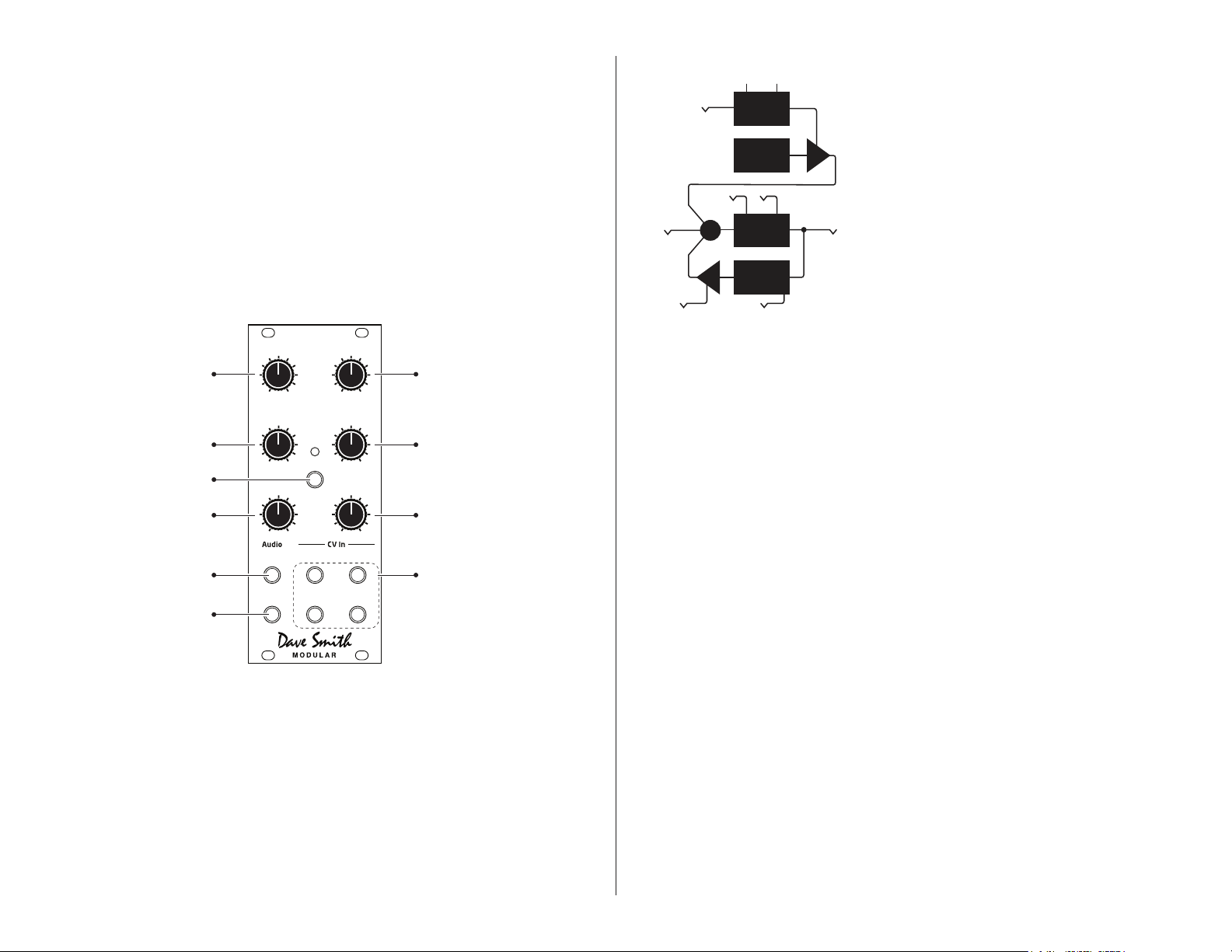
DECAYATTA CK
TRIGGER
ENVELOPE
NOISE
FREQ RES
+
IN OUT
LPF
FB
DELAY
FEEDBACK AMOUNT
Sets the amount of audio signal
to pass to the tuned feedback path
LOW-PASS FILTER FREQ
Sets the low-pass cutoff frequency
Triggers noise output when
input voltage exceeds 1.5v
Sets the attack time for the output level
of noise when using Trigger In
DSM03 Front Panel
-5v to +5v
-10v to +10v
TRIGGER IN
0 to +10v
ATTACK
AUDIO INPUT
-2.5v to +2.5v
AUDIO OUTPUT
-2.5v to +2.5v
FEEDBACK
DSM03
Amount
LPF Freq Resonance
Attack Decay
Input
Output
Trigger In
Fbk Amt
LPF Freq
Tuning
Tuning
Resonance
FEEDBACK TUNING
-5v to +5v
Sets the delay time for the
tuned feedback from 8Hz to 64kHz
RESONANCE
-5v to +5v
Sets the amount of resonance applied
to the low-pass filter cutoff
DECAY
Sets the decay time for the output level
of noise when using Trigger In
VOLTAGE CONTROL INPUTS
8mm input jacks for voltage control of
Feedback Amount, Tuning
LPF Frequency, and Resonance
FB AMOUNT
DSM03 Circuit Diagram
TUNING
About Tuned Feedback
The DSM03 Feedback Module’s tuned feedback delay has a 9-octave range, which is
most noticeable when it oscillates. The tuned feedback loop will track reasonably well
at 1V/octave over a 3-4 octave range via control voltage (CV). Because the low-pass
lter is in the feedback path, it is important to adjust the lter settings for best results.
In other words, the lter settings will affect tracking accuracy. Setting the lpf freq knob
to 12 o’clock is a good starting point. When an audio signal is passed through the input,
the feedback tends to lock to frequencies of the input signal. So, a pitched audio input
will result in closer feedback tracking, while non-pitched audio will give less predictable
results.
Using the DSM03
The DSM03 has many uses, including as a signal processor and as a tone generator.
Signal Processing
You can create a broad variety of effects with the DSM03 by processing an audio signal
though the tuned feedback path (and ltering it if desired). Experiment with the Tuning
parameter to vary the effect in subtle and not-so-subtle ways.
21
Page 2

To use the DSM03 as a signal processor:
1. Connect an audio signal to the DSM03’s audio input jack.
2. Connect the DSM03’s audio output to a mixer or other module that provides audio output.
3. Adjust the tuning parameter manually or connect a control voltage to its voltage control input
to modulate it.
4. Adjust the lpf freq and resonance parameters manually or connect a control voltage to their
voltage control inputs to apply additional processing to the sound.
DSM03 Specications
IN/OUT
• Feedback Amount CV: -5V to +5V
• Tuning CV: -5V to +5V
• LPF Freq CV: -10V to +10V
• Resonance CV: -5V to +5V
Tone Generation
You can also use the DSM03 as a tone generator through its Karplus-Strong plucked
string synthesis capabilities. In classic Karplus-Strong synthesis, a short excitation
waveform (white noise) is generated. This excitation is output and fed back into a
delay line. The output of the delay line is fed through a lter (the low-pass lter).
The lter characteristics determine the harmonic structure of the decaying tone. The
ltered output is mixed back into the output and fed back into the delay line.
To use the DSM03 as a tone generator:
1. Connect a control voltage signal of 1.6V or greater to the DSM03’s trigger in jack.
2. Connect the DSM03’s audio output to a mixer or other module that provides audio output.
3. Adjust the attack and decay parameters to shape the envelope of the generated sound.
4. Adjust the tuning parameter manually or connect a control voltage to its voltage control input
to modulate it.
5. Adjust the lpf freq and resonance parameters manually or connect a control voltage to their
voltage control inputs to shape the harmonic content of the generated sound.
• Audio In: -2.5V to +2.5V
• Audio Out: -2.5V to +2.5V
• Audio Trigger In: 0 to +10V
POWER
• Internal power connector (ribbon cable included)
CURRENT DRAW (5V or 12V operation set by jumper)
Using 5V power supply:
• +5V = 200 mA
• +12V = 10mA
• -12V = 20mA
Using 12V supply only:
• +12V = 210mA
• -12V = 20mA
PHYSICAL SPECS
• 1.99″ W x 5.06″ H (50.5 mm x 128.5 mm)
• Width: 10 HP
• Depth (measured from back of panel with power cable installed): 1.54″ (39 mm)
INCLUDED
• Mounting screws
• Ribbon cable for power connection
3 4
Page 3

Product Support and Warranty
Contacting Technical Support
If you are having a problem with the DSM03, contact Technical Support at support@
davesmithinstruments.com. Please include the purchase date.
Warranty Repair
Dave Smith Instruments warrants that the DSM03 will be free from defects in materials
and/or workmanship for 1 year from the date of purchase. Please register your product
online at www.davesmithinstruments.com to establish the date of purchase. (This is not
a requirement for warranty service, but it will help expedite the process.)
Please contact support@davesmithinstruments.com to determine the best course of
action for getting your DSM03 repaired. For your own protection, as well as ours,
please do not return any product to Dave Smith Instruments without a return authorization (RA) number. To issue an RA number, Technical Support needs:
• Your name
• Your return address
• Your email address
• A phone number where you can be reached
• The date of purchase and where purchased
If you need to return your DSM03 for repair, you are responsible for getting it to DSI.
We highly recommend insuring it and packing in the original packaging. Damage resulting from shipping a product with insufcient packaging is not covered by warranty.
 Loading...