

Page 1
MENU
UP MUTE
ENTER
ASPECT
-
VOL
ZOOM
HEADPHONE
POWER
+
HDMI-1 HDMI-2 BLUE PATTERN
SDI
CV1
YUV
DOWN
PIPFUNCTIONCV2
17.3” HD/SD TFT
LCD MONITOR
TLM-170P/TLM-170PM
/TLM-170PR
Instruction manual
17.3” 3G-SDI FULL HD TF T LCD MONITORTLM-170P
Page 2

Table of Contents
FCC COMPLIANCE STATEMENT .................................................................................................................................... 3
WARNINGS AND PRECAUTIONS .................................................................................................................................. 3
WARRANTY ................................................................................................................................................................. 4
STANDARD WARRANTY ......................................................................................................................................................... 4
THREE YEAR WARRANTY ....................................................................................................................................................... 4
DISPOSAL .................................................................................................................................................................... 4
1. INTRODUCTION ................................................................................................................................................... 5
1.1 FEATURES ............................................................................................................................................................... 5
1.2 TLM-170P MODEL TYPES ........................................................................................................................................ 6
1.3 COM PATIBL E RESOLUTIONS AND FORM ATS .................................................................................................................... 6
2. CONNECTIONS AND CONTROLS........................................................................................................................... 7
2.1 FRONT PANEL .......................................................................................................................................................... 7
2.2 REAR PANEL ............................................................................................................................................................ 8
3 FUNCTION BUTTON - PIXEL ZOOM FEATURE ......................................................................................................10
4. OSD MENUS .......................................................................................................................................................10
4.1 MAIN MENU ...................................................................................................................................................... 10
4.2 MAIN ADJUST .................................................................................................................................................... 10
4.3 COLOR ADJUST .................................................................................................................................................. 11
4.4 SCAN SETTING ................................................................................................................................................... 11
4.5 INFORMATION ................................................................................................................................................... 11
4.6 PIP SETTING ....................................................................................................................................................... 11
4.7 LANGUAGE ........................................................................................................................................................ 12
4.8 SETUP MENU ..................................................................................................................................................... 12
4.9 SPECIAL FUNCTION I .......................................................................................................................................... 12
4.10 SPECIAL FUNCTION II ......................................................................................................................................... 12
4.11 SETUP NETWORK .............................................................................................................................................. 12
4.12 UPDAT E F.W. ...................................................................................................................................................... 13
4.13 FAC TORY RESET ................................................................................................................................................. 13
4.14 AUDIO CONTROL ............................................................................................................................................... 13
5. REMOTE SET UP USING AN EXISTING DHCP NETWORK ......................................................................................14
6. REMOTE SET UP USING A DIRECT COMPUTER CONNECTION ..............................................................................15
7. FIRMWARE UPDATE PROCEDURE .......................................................................................................................16
8. TLM-170PR: FITTING THE 19” RACK EARS TO THE TLM-170P ..............................................................................17
9. TLM-170PM: FITTING THE MONITOR TO A 19” RACK .........................................................................................18
10. SPECIFICATIONS ..............................................................................................................................................19
SERVICE AND SUPPORT..............................................................................................................................................20
Disclaimer of Product and Services
The information offered in this instruction manual is intended as a guide only. At all times, Datavideo Technologies will try to give
correct, complete and suitable information. However, Datavideo Technologies cannot exclude that some information in this manual,
from time to time, may not be correct or may be incomplete. This manual may contain typing errors, omissions or incorrect
information. Datavideo Technologies always recommend that you double check the information in this document for accuracy
before making any purchase decision or using the product. Datavideo Technologies is not responsible for any omissions or errors, or
for any subsequent loss or damage caused by using the information contained within this manual. Further advice on the content of
this manual or on the product can be obtained by contacting your local Datavideo Office or dealer.
2
Page 3

FCC Compliance Statement
This device complies with part 15 of the FCC rules. Operation is subject to the following two
conditions:
(1).This device may not cause harmful interference, and
(2).This device must accept any interference received, including interference that may cause
undesired operation.
Warnings and Precautions
1. Read all of these warnings and save them for later reference.
2. Follow all warnings and instructions marked on this unit.
3. Unplug this unit from the wall outlet before cleaning. Do not use liquid or aerosol cleaners. Use
a damp cloth for cleaning.
4. Do not use this unit in or near water.
5. Do not place this unit on an unstable cart, stand, or table. The unit may fall, causing serious
damage.
6. Slots and openings on the cabinet top, back, and bottom are provided for ventilation. To ensure
safe and reliable operation of this unit, and to protect it from overheating, do not block or
cover these openings. Do not place this unit on a bed, sofa, rug, or similar surface, as the
ventilation openings on the bottom of the cabinet will be blocked. This unit should never be
placed near or over a heat register or radiator. This unit should not be placed in a built-in
installation unless proper ventilation is provided.
7. This product should only be operated from the type of power source indicated on the marking
label of the AC adapter. If you are not sure of the type of power available, consult your
Datavideo dealer or your local power company.
8. Do not allow anything to rest on the power cord. Do not locate this unit where the power cord
will be walked on, rolled over, or otherwise stressed.
9. If an extension cord must be used with this unit, make sure that the total of the ampere ratings
on the products plugged into the extension cord do not exceed the extension cord rating.
10. Make sure that the total amperes of all the units that are plugged into a single wall outlet do
not exceed 15 amperes.
11. Never push objects of any kind into this unit through the cabinet ventilation slots, as they may
touch dangerous voltage points or short out parts that could result in risk of fire or electric
shock. Never spill liquid of any kind onto or into this unit.
12. Except as specifically explained elsewhere in this manual, do not attempt to service this
product yourself. Opening or removing covers that are marked “Do Not Remove” may expose
you to dangerous voltage points or other risks, and will void your warranty. Refer all service
issues to qualified service personnel.
13. Unplug this product from the wall outlet and refer to qualified service personnel under the
following conditions:
a. When the power cord is damaged or frayed;
b. When liquid has spilled into the unit;
c. When the product has been exposed to rain or water;
d. When the product does not operate normally under normal operating conditions.
Adjust only those controls that are covered by the operating instructions in this manual;
improper adjustment of other controls may result in damage to the unit and may often
require extensive work by a qualified technician to restore the unit to normal operation;
e. When the product has been dropped or the cabinet has been damaged;
f. When the product exhibits a distinct change in performance, indicating a need for
service.
3
Page 4

Warranty
Standard Warranty
• Datavideo equipment are guaranteed against any manufacturing defects for one year from
the date of purchase.
• The original purchase invoice or other documentary evidence should be supplied at the
time of any request for repair under warranty.
• The product warranty period begins on the purchase date. If the purchase date is unknown,
the product warranty period begins on the thirtieth day after shipment from a Datavideo
office.
• All non-Datavideo manufactured products (product without Datavideo logo) have only one
year warranty from the date of purchase.
• Damage caused by accident, misuse, unauthorized repairs, sand, grit or water is not
covered under warranty.
• Viruses and malware infections on the computer systems are not covered under warranty.
• Any errors that are caused by unauthorized third-party software installations, which are not
required by our computer systems, are not covered under warranty.
• All mail or transportation costs including insurance are at the expense of the owner.
• All other claims of any nature are not covered.
• All accessories including headphones, cables, and batteries are not covered under warranty.
• Warranty only valid in the country or region of purchase.
• Your statutory rights are not affected.
Three Year Warranty
• All Datavideo products purchased after July 1st, 2017 are qualified for a
free two years extension to the standard warranty, providing the
product is registered with Datavideo within 30 days of purchase.
• Certain parts with limited lifetime expectancy such as LCD panels, DVD
drives, Hard Drive, Solid State Drive, SD Card, USB Thumb Drive, Lighting, Camera module,
PCIe Card are covered for 1 year.
• The three-year warranty must be registered on Datavideo's official website or with your
local Datavideo office or one of its authorized distributors within 30 days of purchase.
Disposal
For EU Customers only - WEEE Marking.
This symbol on the product indicates that it should not be treated as
household waste. It must be handed over to an applicable take-back scheme
for the recycling of Waste Electrical and Electronic Equipment. For more
detailed information about the recycling of this product, please contact your
local Datavideo office or your local recycling centre.
CE Marking is the symbol as sho wn on the left of this page. The lett ers "CE" are
the abbreviation of French phrase "Conformité Européene" which literally means
"European Conformity". The term initially used was "EC Mark" and it was officially
replaced by "CE Marking" in the Direc tive 93/68/EEC in 1993. "CE Marking" is no w
used in all EU official documents.
4
Page 5

1. Introduction
The Datavideo TLM-170P is a 17.3” TFT LCD monitor that delivers superb FULL HD 1080P image
quality from various inputs including 3G-SDI. The monitor is a professional grade panel designed to
give excellent colour and video performance across a range of formats and standards as well as
24/7 operation.
The TLM-170P front panel buttons allow quick and easy selection of source input as well as PIP,
Aspect ratio, Blue only, Pattern (Colour Bars), Menu and audio controls. Input HD/SD sources via
the rear panel SDI, HDMI, Component (Y, Pb, Pr) and Composite connections as well as monitoring
RCA phono or embedded SDI / HDMI audio.
The Datavideo TLM-170P monitor has an on-screen display (OSD) menu which allows control and
set up of brightness, contrast, saturation, hue, sharpness, colour temperature and picture in
picture. It also has RJ-45 TCP/IP connector to allow remote set up of the monitor using a PC / Mac
based web browser. The menus can also be used to display onscreen overlays for frame marker, 4:3
marker, 16:9 Marker, Cinema Zone Marker, Center Point, embedded SDI Timecode and Monitor
Title.
The Datavideo TLM-170P monitor can be operated from AC or 12V DC power making it flexible for
use in a Studio, Gallery, Post Production Edit Suite or even in an OB Van.
That’s Datavideo; sharing the value!
To get more value out of this equipment please take a few minutes to read this manual thoroughly
as this will help you familiarise yourself with all aspects of the TLM-170P monitor.
1.1 Features
• 17.3” FULL HD 1080p LCD Panel with Underscan and Overscan menu options.
• Digital Video Inputs: Single BNC HD-SDI or SDI and HDMI x2 [ HDMI1, HDMI 2 ].
• Analogue Video Inputs: Component [ Y,Pb,Pr ], Composite x2 [ CV1, CV2 ].
• Single BNC SDI /HD-SDI loop through / bypass.
• Composite loop through of CV2 input.
• Mono Audio Inputs: Single RCA phono socket for analogue inputs.
• Digital Audio Inputs: via SDI or HDMI inputs.
• Head phone 3.5mm stereo jack socket for discrete audio monitoring.
• Front Panel Buttons allow quick and easy selection of source input as well as PIP, Aspect Ratio,
Blue only, Pattern (Colour Bars), Menu and audio controls.
• Colour temperature menu option has 3 modes (6500K, 9300K and user defined)
• OSD audio level peak meter for SDI and HDMI based digital audio inputs.
• On screen overlays for frame marker 80%, 90%, 4:3 marker, 16:9 Marker, Cinema Zone
Marker, Center Point, embedded SDI Timecode and Monitor Title.
• Bi-colour Tally light and 3.5mm Jack Tally input socket.
• Analogue Audio external speaker outputs L-, L+ and R-, R+ [Max 5v p - p (2w)].
• RJ-45 TCP/IP connection allows remote set up of the monitor using a PC / Mac based browser.
• USB 2.0 port for easy update of firmware with a USB 2.0 pen drive.
5
Page 6
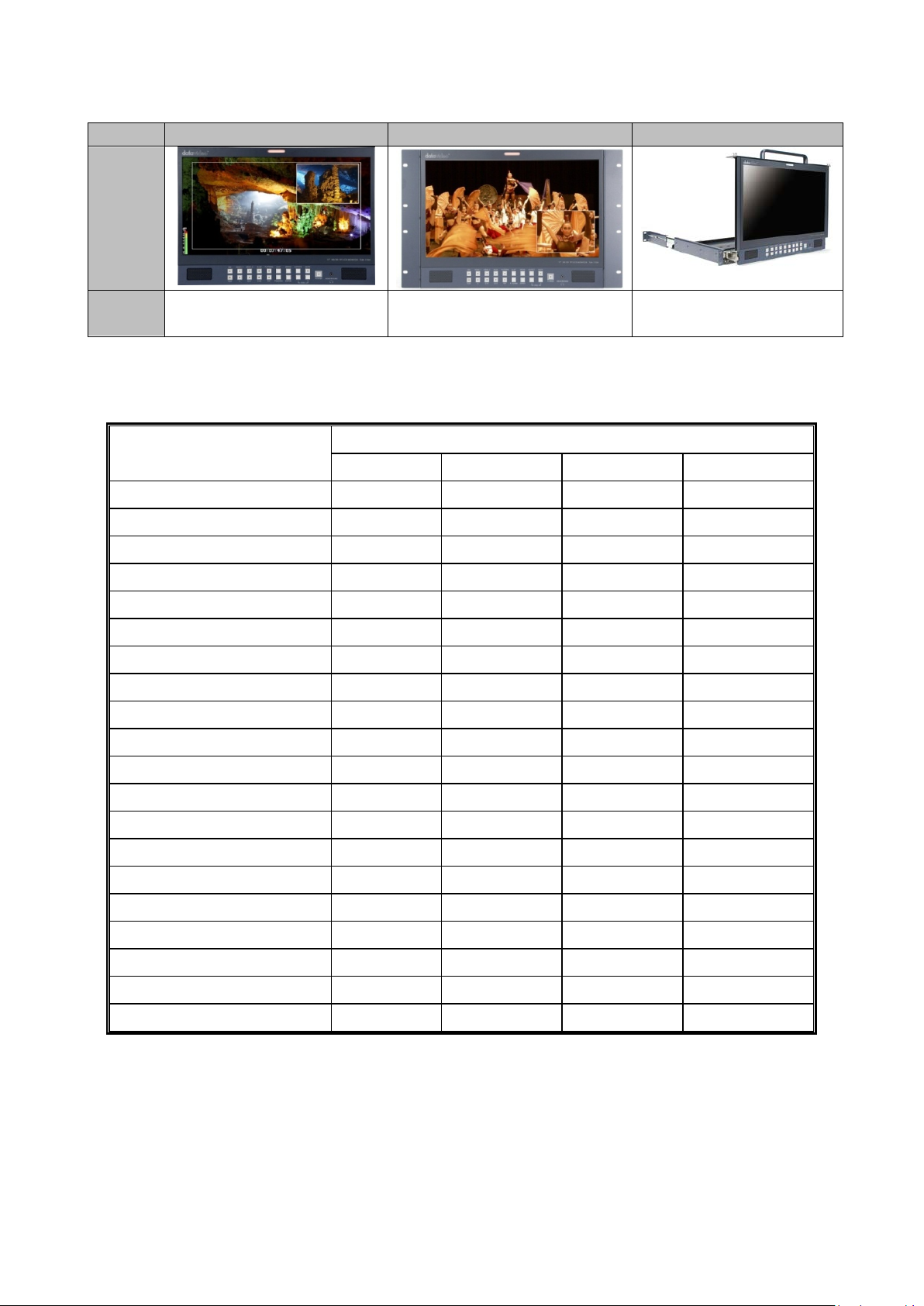
1.2 TLM-170P Model Types
Model
TLM-170P
TLM-170PR
TLM-170PM
Image
System
Desktop
7U Rack Mount
1U Mobile Tray Rack
Mount
TLM-170P Interface
HDMI
SDI
YPbPr
Composite
1920x1080P @ 59.94
Support
Support
x
x
1920x1080P @ 60
Support
Support
x
x
1920x1080P @ 50
Support
Support
x
x
1920x1080P @ 29.97
Support
Support
Support
x
1920x1080P @ 25
Support
Support
Support
x
1920x1080P @ 30
Support
Support
Support
x
1920x1080P @ 23.98
Support
Support
Support
x
1920x1080P @ 23.98SF
x x x
x
1920x1080P @ 24SF
Support
x x x
1920x1080i @ 59.94
Support
Support
Support
x
1920x1080i @ 60
Support
Support
Support
x
1920x1080i @ 50
Support
Support
Support
x
1280x720P @ 59.94
Support
Support
Support
x
1280x720P @ 60
Support
Support
Support
x
1280x720P @ 50
Support
Support
Support
x
1280x720P @ 23.98
x x x
x
1280x720P @ 24
x x x
x
720 x 480i (NTSC)
Support
Support
Support
Support
720 x 576i (PAL)
Support
Support
Support
Support
1.3 Compatible Resolutions and Formats
Format
1920x1080P @ 24 Support Support Support x
The TLM-170P panel will support/display the following 60Hz computer resolutions when supplied
via a standard DVI to HDMI cable.
Please note the TLM-170P panel is natively 1920 x 1080 pixels so certain resolutions may be slightly
edge cropped and bars/columns may be shown with other resolutions when the panel is switched
between 16:9 and 4:3 using the aspect button.
6
Page 7

SVGA 800 x 600 4:3
XGA 1024 x 768 4:3
WXGA 1280 x 768 16:9
WXGA 1280 x 800 16:10
2. Connections and Controls
2.1 Front Panel
Resolution Aspect
1152 x 864 4:3
Bi-Colour Tally Light: Can be used to indicate Live (Red).
Source Select Buttons: Select the type of input you are using SDI, HDMI, YUV, CV; The active input
will be indicated by a red LED on the Source Button.
BLUE: Press this button to eliminate the red and green component of input signals. Only the blue
component of an input is displayed on the screen. This allows adjustments of chroma and phase.
(Phase adjustment is effective with NTSC signals).
Function: Press this button to zoom in your HD-SDI video source on the screen.
7
Page 8

* See Function Button – Pixel zoom feature for more details.
Pattern Button: When pressed displays internally generated SMPTE 75% Colour Bars. Press again
to return to the previously selected video input.
PIP Button: Activates Picture in Picture Mode.
Menu Navigation Buttons: Display and navigate the set up menus - See Menu Options for more
details.
Aspect Ratio Button: Sets the Aspect Ratio to 16:9 / 4:3
Mute Button: Mutes the audio from the internal speakers or headphone socket.
Volume Control: Adjusts the speaker / headphone volume up / down.
Headphone Socket: 3.5mm headphone socket; internal speaker circuit will automatically mute
when headphones are connected.
N.B. Main Power On/Off switch is located on the rear of the TLM-170P.
2.2 Rear Panel
8
Page 9

LAN Remote Control: Use a crossover Ethernet cable for direct connection between TLM-170P
and the PC RJ-45 port. See Remote Control Setup section for more details.
USB 2.0 Port - For firmware updates only. See Firmware Update section for more details.
SDI Input & Loop Through: BNC Input for HD / SD SDI with a loop through output.
HDMI Input - Video and Audio input from HDMI.
3.5mm Tally Light Input: Tally light information can be supplied to the TLM-170P from the
Datavideo RMC-140, TB-5 or TB-10 or the ITC-100SL / ITC-200B/E via this socket.
Analog Audio Inputs: Mono audio inputs to correspond to the analogue video inputs (CV 1 & CV 2).
Composite Video Inputs 1 & 2: BNC connectors for composite video with one loop through output.
Component Video Input: BNC connectors for Component (YUV (Y/R-Y/B-Y)) Video.
External Speaker Output Connections: Speaker Output connections Max 5v p - p (2w)
DC In Socket: 2.1mm, In Line Power Socket with screw lock, for connecting the suitable 12v 30W
feed.
On / Off Switch: Main on / off switch, switches the TLM-170P on and off.
9
Page 10

3 Function Button - pixel zoom feature
You can choose:
MAIN ADJUST
COLOR ADJUST
SCAN SETTING
INFORMATION
PIP SETTING
LANGUAGE
SETUP MENU
SPECIAL FUNCTION I
SPECIAL FUNCTION II
SETUP NETWORK
SETUP F. W.
FACTORY RESET
AUDIO CONTROL
EXIT
You can choose:
BRIGHTNESS
0~100
CONTRAST
0~100
SHARPNESS
0~100
SATURAT ION
0~100
TINT
0~100
BACK LIGHT
0~100
3D COMB
DISABLE / ENABLE
NR
HIGHD / MID / LOW / OFF
MPEG NR
HIGHD / LOW / OFF
This feature is designed for use with HD-SDI and HDMI sources above 720p resolution. Press this
button to zoom in to the video on the display. This is strictly a zooming function and does not alter
the native aspect ratio of the source pixels to fill the screen.
The FUNCTION button allows you to toggle the Pixel Zoom feature between zoom x1, x2, x4 and
x8.
When turned ON the zoomed display may be moved left or right using the VOL + /- ZOOM keys
and up or down using the up/down keys.
A Flashing FUNCTION button light will be activated whenever you are in a zoomed mode as a
reminder/warning that the entire incoming signal is not being shown on the monitor.
To exit zoomed mode, simply press down on the MENU key. To exit the Pixel Zoom feature entirely
simply press the MENU button once more.
4. OSD Menus
The TLM-170P is set up using an OSD menu system. To display the OSD menu press the MENU
button. This menu system is navigated using the Up / Down buttons to change a value or to
highlight a menu option. Press the Enter button to select an option or confirm a value.
4.1 MAIN MENU
4.2 MAIN ADJUST
10
Page 11

DLC
DISABLE / ENABLE
VOLUME
0~100
EXIT
You can choose:
6500
9300
USER COLOR
RED
0~100
GREEN
0~100
BLUE
0~100
EXIT
You can choose:
UNDER SCAN
full image
OVER SCAN
cropped image
Display:
H. FREQUENCY
V. FREQUENCY
RESOLUTION
NTSC / PAL / SECAM
You can choose:
PIP
ON / OFF
SOURCE
*see below
POSITION
LF-TOP / RT-TOP / RT-BOT / LF-BOT
SIZE
LARGE / SMALL / MID
SWAP
swap PIP source and Main source
EXIT
4.3 COLOR ADJUST
4.4 SCAN SETTING
3D COMB is for video noise suppression.
NR is for video Noise Reduction.
MPEG NR is for MPEG format Noise Reduction.
DLC is for Dynamic Luminance Control.
4.5 INFORMATION
This mode will display the video resolution.
4.6 PIP SETTING
Main/Background source is chosen on the front panel first before entering the PIP
menu.
PIP window must be an analogue source if Main source is a digital source, or vice
versa.
It is not possible to use analogue inputs for both PIP window and Main source.
It is not possible to use digital inputs for both PIP window and Main source.
Examples
If main source = HD-SDI [digital] then PIP window choice = YUV or Composite
[analogue]
If main source = HDMI [digital] then PIP window choice = YUV or Composite
[analogue]
11
Page 12

If main source = YUV [analogue] then PIP window choice = SDI or HDMI [digital]
You can choose:
English
[default]
Español
Deutsch
Español
Italiano
Dutch
Português
EXIT
You can choose:
OSD TIMEOUT
5~120 sec
EXIT
You can choose:
FRAME RATIO
80 / 90 / 0FF
4:3 MARK LINE
ON / OFF
CENTRAL MARK
ON / OFF
CINEMA ZONE
MARK
ON / OFF
MARK TYPE
OVERLAY / TRANSPARENT
EXIT
You can choose:
TIMECODE SETUP (VALID FOR SDI ONLY)
TITLE EDIT
TITLE DISPLAY
ON / OFF
TITLE POSITION
MID-TOP / MID-BOT
FONT SIZE
SMALL / LARGE
FONT COLOR
RED / GREEN / ORANGE / WHITE
EDIT TITLE
A~Z
EXIT
You can choose:
DHCP
ON / OFF
User choice
IP
127.127.127.127.
User defined
Or set by DHCP if DHCP=ON
MASK
255.255.255.255.
User defined
Or set by DHCP if DHCP=ON
GATEWAY
127.127.127.127
User defined
Or set by DHCP if DHCP=ON
If main source = CV1 [analogue] then PIP window choice = SDI or HDMI [digital]
4.7 LANGUAGE
4.8 SETUP MENU
4.9 SPECIAL FUNCTION I
4.10 SPECIAL FUNCTION II
4.11 SETUP NETWORK
12
Page 13

MAC
xx.xx.xx.xx.xx.xx
unique to monitor
cannot be changed
EXIT
You can choose:
UPDATE SCALER F.W.
SCALER VER:
UPDATE FPGA F.W.
FPGA VER:
EXIT
Push ENTER button to reset the TLM-170P to restore the factory settings or default settings.
You can choose:
INTERNAL AUDIO
ON / MUTE / MUTE CTROL
EXTERNAL AUDIO
ON / MUTE / MUTE CTROL
AUDIO INDICATOR*
ON / OFF
AUDIO CHANNEL L
1 AUDIO CHANNEL R
2 EXIT
See Remote Setup sections for more details.
4.12 UP DATE F.W.
See Firmware Update Procedure section for more details.
4.13 FACTORY RESET
4.14 AUDIO CONTROL
*dBFS audio peak meter shown as overlay in bottom left hand corner of display when this option is
ON. This display shows 8 channels of audio with SDI sources and 2 channels with other sources.
13
Page 14

5. Remote Set Up using an existing DHCP Network
The TLM-170P can be remotely set up using a computer web browser and the existing DHCP LAN.
In this way a gallery of TLM-170P monitors can be set up from one computer if enough network
connections exist.
1. Use a normal Ethernet RJ-45 patch cable, straight through, to connect TLM-170P to an
existing LAN wall socket/switch.
2. Power on the TLM-170P monitor and press the MENU button to display the OSD menu.
3. Using the Up / Down buttons highlight SETUP NETWORK and press ENTER.
4. Set the menu option DHCP to ‘’ON’’ and press ENTER.
The same OSD menu screen will now show the IP address given by the network to the TLM170P monitor. Make a note of this displayed IP address.
5. From a computer on the same DHCP LAN network open a web browser such as Internet
Explorer or Google Chrome. Delete the contents of the address bar at the top of the
browser window and enter the IP address of the TLM-170P that you just made a note of
earlier and press ENTER.
6. The TLM-170P REMOTE SET UP interface should now be displayed in the web browser.
7. You can now use the computer’s mouse and keyboard to change the monitor’s settings.
Once the above steps have been completed the next time you want to change settings remotely
you can re-start from step 5.
14
Page 15

6. Remote Set Up using a direct computer connection
The TLM-170P can be remotely set up using a computer web browser and an Ethernet crossover
cable. No existing computer network is used. The Ethernet crossover cable is connected to the
TLM-170P monitor and the computer/laptop being used.
1. Use an Ethernet RJ-45 crossover cable to connect the TLM-170P directly to the computer being
used.
2. Power on the TLM-170P monitor and press the MENU button to display the OSD menu.
3. Using the Up / Down buttons highlight SETUP NETWORK and press ENTER.
4. Set the menu option DHCP to ‘’OFF’’ and press ENTER.
5. Then enter into the TLM-170P …
IP Address: 192.168.0.210
Subnet Mask: 255.255.255.0
Gateway: 192.168.0.1
6. Now open the Network and Sharing Center window on the Windows computer. Open the Local
Area Network Properties window and make a note of any displayed IP address or settings so
you can return the computer back to its original settings later if necessary.
7. Now change the Computer’s TCP/IP property settings as shown below.
Select ‘Use the following IP Address’ radio button.
Then enter into the computer …
IP Address: 192.168.0.205
Subnet Mask: 255.255.255.0
Gateway: 192.168.0.1
8. Now save and close any open network related windows on the computer.
9. From the computer desktop open a web browser such as Internet Explorer or Google Chrome.
10. Delete the contents of the address bar at the top of the browser window and enter the IP
address of the TLM-170P which should be 192.168.0.210 if you are following the example here.
11. When you enter the IP address in the web browser the TLM-170P’s remote settings interface
should be displayed in the browser window.
15
Page 16

7. Firmware update procedure
From time to time Datavideo may release new firmware to either add new features or to fix
reported bugs in the current TLM-170P firmware. Customers can update the firmware themselves
if they wish or they can contact their local dealer or reseller for assistance should they prefer this
method.
This page describes the firmware update process and it should take approximately 15 minutes
total time to complete.
As well as a working TLM-170P you will need:
The latest firmware update for the TLM-170P monitor.
This firmware file can be obtained from your local Datavideo office or dealer.
USB 2.0 pen drive 128MB or larger with a USB A connector.
Once started the update process should not be interrupted in any way as this could result in a
non-responsive unit.
How to update the Scaler firmware
1. Unzip / extract the supplied zipped archive or rar folder.
2. Wipe the contents of the USB 2.0 pen drive so it is empty.
3. Transfer / copy the unzipped / extracted file to the USB 2.0 pen drive.
4. Plug the USB 2.0 pen drive into the USB 2.0 port labelled MAINTENANCE on the rear of the
TLM-170P monitor.
5. Power the monitor on and press the MENU button to display the OSD Main Menu.
6. Using the OSD Menu buttons [UP, DOWN & ENTER] highlight and select the SETUP F.W.
option.
7. Using the OSD Menu buttons [UP, DOWN & ENTER] highlight and select UPDATE SCALER F.W.
8. The TLM-170P tally light will flash different colours whilst the update is in progress.
9. The TLM-170P monitor will reboot itself at the end of the process.
How to update the FPGA firmware
1. Unzip / extract the supplied zipped archive or rar folder.
2. Wipe the contents of the USB 2.0 pen drive so it is empty.
3. Transfer / copy the unzipped / extracted file to the USB 2.0 pen drive.
4. Plug the USB 2.0 pen drive into the USB 2.0 port labelled MAINTENANCE on the rear of the
TLM-170P monitor.
5. Power the monitor on and press the MENU button to display the OSD Main Menu.
6. Using the OSD Menu buttons [UP, DOWN & ENTER] highlight and select the SETUP F.W.
option.
7. Using the OSD Menu buttons [UP, DOWN & ENTER] highlight and select UPDATE FPGA F.W.
8. The TLM-170P tally light will flash different colours whilst the update is in progress.
9. The TLM-170P monitor will reboot itself at the end of the process.
Once started the update process should not be interrupted in any way as this could result in a
non-responsive unit.
16
Page 17

8. TLM-170PR: Fitting the 19” Rack Ears to the TLM-170P
The TLM-170PR is supplied with 19” Rack Ears which allow the monitor to be rack mounted (19”
7U).
Use the supplied screws to attach the left and right rack ears. You will see there are four screws on
either side, as illustrated above, plus additional screws at the base of each rack ear, as illustrated
below.
17
Page 18

9. TLM-170PM: Fitting the monitor to a 19” Rack
The TLM-170PM is designed to rack mount. When folded away it is 1U high, please bear in mind
that when opened for operation the monitor is 7U high, so leave adequate room above for this.
The monitor arrives already fitted with sliding rack rails, these have a length adjustment at the
rear to suit the distance between the front and rear rack rails of your cabinet.
To adjust the length loosen the four adjustment nuts as illustrated below, and pull the side rails
back as far as is required. Then re-tighten the nuts.
Mount the monitor in your rack with the rear panel facing upwards. Ensure the rack mounting
screws are secured both front and rear.
Once mounted and secure to the rack, unscrew the two locking screws on either side of the front
panel, and pull the monitor forward using the handle. Once the monitor is fully forward simply
hinge it up into a vertical position.
To fold away, pull the top of the monitor forward, so that it hinges down to a horizontal position,
then push it back into the rack until you are able to screw in the locking screws.
N.B. When folding the monitor away be careful not to trap your fingers or scrape your hand on the
rack cabinet.
18
Page 19

10. Specifications
SMPTE-425M-A/B
SMPTE-274M
1080p (60/59.94/50/30/25/24)
1080p (30 / 29.97)
Speaker cable output
(L-, L+, R-, R+) Max 5v p - p (2w)
Size 17.3''
Resolution 1920 x 1080
LCD
Video INPUT
Video OUTPUT
SDI Signal Format
View Angle
White Luminance 400cd
Contrast 600
HDMI x 2 HDMI Ver. 1.3
BNC x 1 3Gbps/ HD/SD-SDI
BNC x3 Component
BNC x 2 Composite
BNC x 1 HD-SDI Loop Through Output
BNC x 1 CV2 Loop Thru Output
SMPTE-292M
SMPTE-296M 720p (60 / 59.94 / 50)
Top: 60 deg Bottom: 60 deg
Left: 80 deg Right: 80 deg
1080i (60/59.94/50)
SMPTE-259M 480i (59.94) 576i(50)
Supports SD/HD-SDI embedded audio
Supports HDMI embedded audio (Ver.1.3)
Audio Input
connections
Audio Output Internal Speaker
Maintenance USB x 1 USB 2.0 FW Auto Upgrade
Power DC 12V
Operating Temperature 0 °C to 50 °C
Storage Temperature -10 °C to 60 °C
Accessory New professional Stand
Weight 6 Kg
Speaker Output connections
Max 5v p - p (2w)
19
Page 20

DATAVIDEO WORLDWIDE OFFICES
Service & Support
It is our goal to make owning and using Datavideo products a satisfying experience. Our support sta is available
to assist you to set up and operate your system. Contact your local office for specific support requests. Plus,
please visit www.datavideo.com to access our FAQ section.
China Shanghai
Datavideo Technologies China Co
601,Building 10,No.1228,
Rd.Jiangchang,
Jingan District,Shanghai
Tel: +86 21-5603 6599
Fax:+ 86 21-5603 6770
E-mail: service@datavideo.cn
China Beijing
Datavideo Technologies China Co
No. 812, Building B, Wankai Center,
No.316, Wan Feng Road, Fengtai District,
Beijing, China
Tel: +86 10-8586 9034
Fax:+86 10-8586 9074
E-mail: service@datavideo.cn
China Chengdu
Datavideo Technologies China Co
B-823,Meinian square,No.1388,
Middle of Tianfu Avenue,Gaoxin District,
Chengdu,Sichuan
Tel: +86 28-8613 7786
Fax:+86 28-8513 6486
E-mail: service@datavideo.cn
China Fuzhou
Datavideo Technologies China Co
A1-2318-19 Room,No.8, Aojiang Road,
Taijiang District,Fuzhou,Fujian,China
Tel: 0591-83211756,0591-83210187
Fax:0591-83211262
E-mail: service@datavideo.cn
China Jinan
Datavideo Technologies China Co
902, No. 1 business building,
Xiangtai Square, No. 129,
Yingxiongshan Road, Shizhong District,
Jinan City, Shandong Province, China
Tel: +86 531-8607 8813
E-mail: service@datavideo.cn
Hong Kong
Datavideo Hong K ong Ltd
G/ F.,26 Cross Lane
Wanchai, Hong Kong
Tel: +852-2833-1981
Fax:+ 852-2833-9916
E-mail: info@dat avideo.com.hk
India Noida
Datavideo India Noida
A-132, Sec-63,Noida-201307,
India
Tel: +91-0120-2427337
Fax:+91-0120-2427338
E-mail: sales@datavideo.in
India Kochi
Datavideo India Kochi
2nd Floor- North Wing, Govardhan Building,
Opp. NCC Group Headquaters, Chittoor Road,
Cochin- 682035
Tel: +91 4844-025336
Fax:+91 4844-047696
Netherlands
Data video Technologies Europe B V
Floridadreef 106
3565 AM Ut rech t,
Th e Netherlands
Tel: +31-30-261-9 6-56
Fa x: +31-30-261-9 6-57
E-mail: info@dat av ideo.n l
Singapore
Datavideo Visual Technology(S) Pte Ltd
No. 178 Paya Lebar Road #06-07
Singapore 409030
Tel: +65-6749 6866
Fa x:+65-6749 3266
E-mail:info@datavideovirtualset.com
Singapore
Data video Technologies (S ) PTE Lt d
No. 178 Paya Lebar Road #06-03
Singapore 409030
Tel: +65-6749 6866
Fa x:+65-6749 3266
E-mail:s ales@dat av ideo.sg
Taiwan
Datavideo Technologies Co. Lt d
10F. No. 176, Jian 1st Rd.,Chung Ho
District, New Taipei City 235, Taiwan
Tel: +886-2-8227-2888
Fax:+886-2-8227-2777
E-mail:service@dat avideo.com.tw
United States
Datavideo Corporat ion
7048 Elmer Avenue.
Whittier, C A 90602,
U.S.A.
Tel: +1-562-696 2324
Fax:+1-562-698 6930
E-mail:sales@datavideo.comE-mail: sales@datavideo.in
United Kingdom
Data video U K Limi te d
Brookfield House, Brookfield Industrial
Estate, Peakdale Road, Glossop,
Derbyshire, SK13 6LQ
Tel: +44-1457 851 000
Fa x: +44-1457 850 964
E-mail: sales@dat avideo.co. uk
France
Datavideo France s.a.r.l.
Cité Descartes 1, rue Albert Einstein
Champs sur Marne 774477 –
Marne la Vallée cedex 2
Tel: +33-1-60370246
Fa x: +33-1-60376732
E-mail: info@datavideo.fr
Please visit our website for latest manual update.
www.datavideo.com/product/TLM-170P
www.datavideo.com/product/TLM-170PM
www.datavideo.com/product/TLM-170PR
All the trademarks are the properties of their respective owners. Datavideo Technologies Co., Ltd. All rights reserved 2018
Jan-18.2018
Version : E7
 Loading...