

Page 1
Page 2
RR
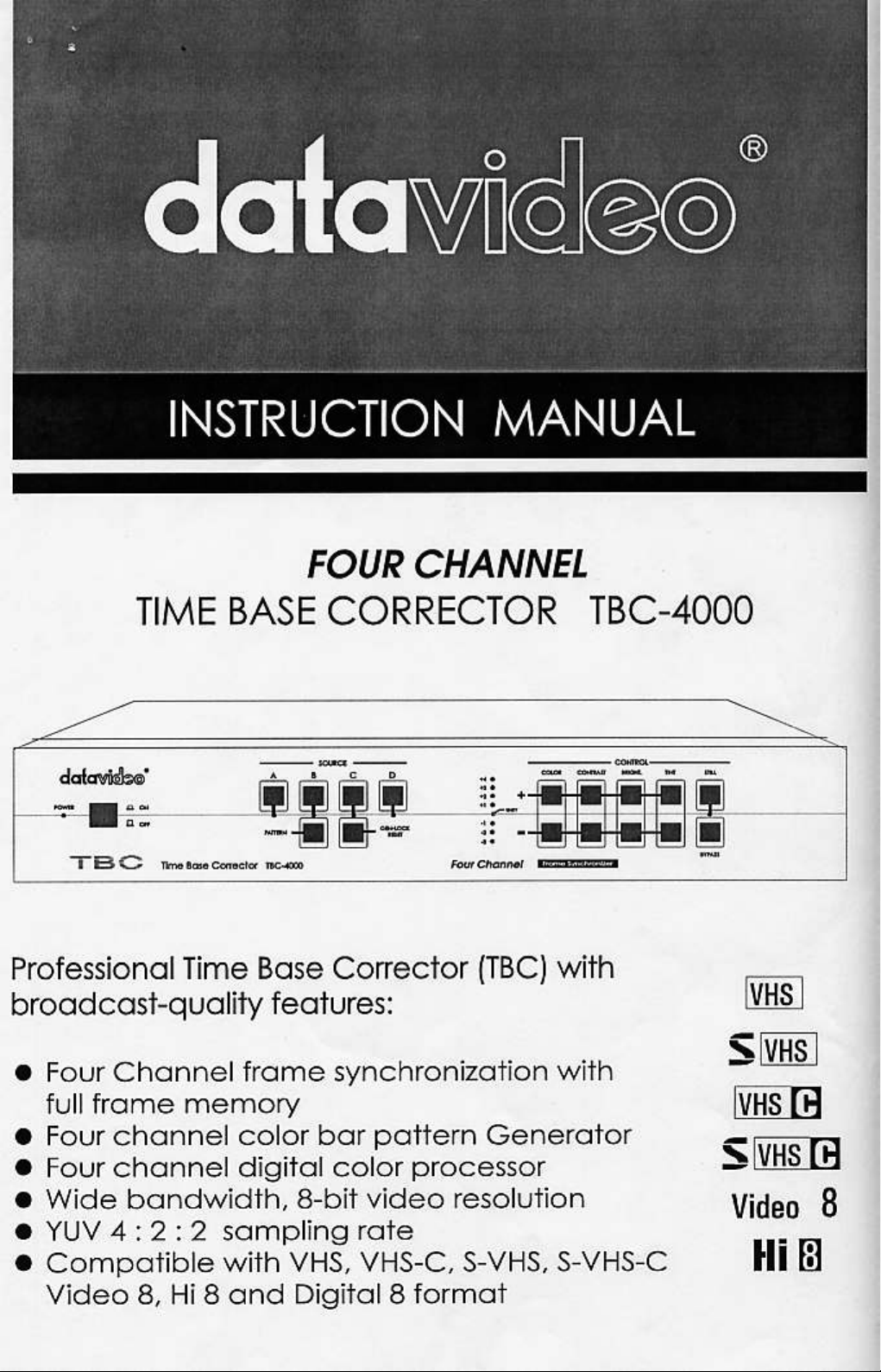
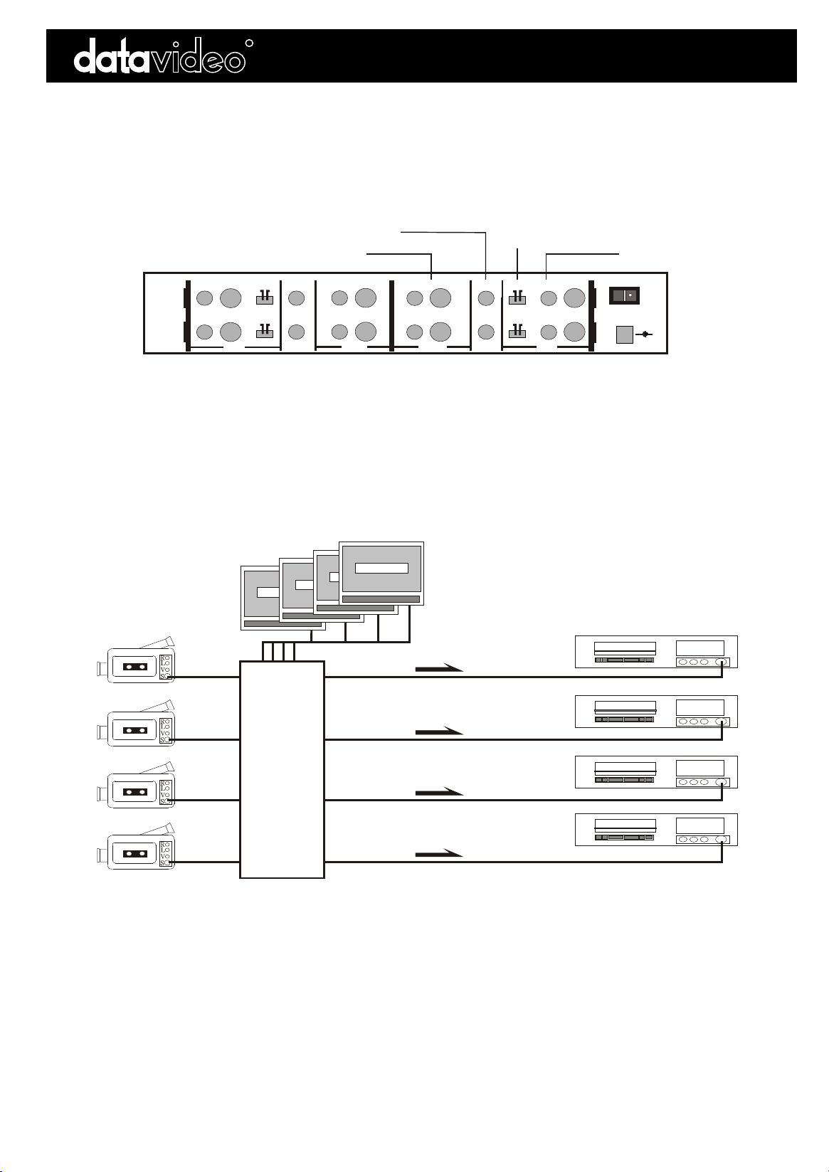
Installation DiagramInstallation Diagram
TBC-4000TBC-4000
Rear Panel of TBC-4000
SOURCES
REMOTE
CAMCORDER
MONITOR OUTPUT
VIDEO OUTPUT
MONITOR
MONITOR
VV
SS
BB
S
SOURCE S V SOURCE V
SOURCE S V SOURCE V
S
V
V
DD
S
S
V
VV
VV
VV
SS
V
OUTPUTOUTPUT
OUTPUTOUTPUT
V/S(Y/C)
INPUT SELECT
MONITOR MONITOR
OUTPUT OUTPUT OUTPUT OUTPUT
VIDEO INPUT
SSVV
SSVV
INPUT INPUT INPUT INPUT
SOURCE MONITORING
TV/Monitor
TV/Monitor
TV/Monitor
TV/Monitor
BCC
A
A
D
A
POWERPOWER
AA
DC IN
DC IN
S
S
9V 18W
9V 18W
CC
MADE IN TAIWANMADE IN TAIWAN
RECORDING VCRRECORDING VCR
RECORDING VCRRECORDING VCR
++
R
R
L
L
S
S
V
V
REMOTE
CAMCORDER
REMOTE
CAMCORDER
REMOTE
CAMCORDER
R
R
S
S
L
L
V
R
R
R
R
V
S
S
L
L
V
V
S
S
L
L
V
V
B
TBC-4000TBC-4000
D
B
RECORDING VCRRECORDING VCR
C
RECORDING VCRRECORDING VCR
D
Page 3

RR
Front Panel Controls:Front Panel Controls:
TBC-4000TBC-4000
RR
POWERPOWER
1. POWER ON/OFF SWITCH
1. POWER ON/OFF SWITCH
ONON
OFFOFF
Time Base Corrector TBC-4000Time Base Corrector TBC-4000
SOURCE SOURCE
A B C DA B C D
PATTERNPATTERN
GEN-LOCK
GEN-LOCK
RESET
RESET
Turns main power to TBC-4000 on and off.
2. SOURCE SWITCHES
2. SOURCE SWITCHES
Selects one of four source channels A to D to
adjust the level of color, contrast,brightness,etc.
The source LED will light up when source is
selected.
3. PATTERN SWITCH
3. PATTERN SWITCH
The TBC-4000 can generate color bar test pattern
on four source channels A to D. To generate a
test pattern, press the Pattern key and hold it for
2 seconds. To remove test pattern, press the
PATTERN switch again.
4. GEN-LOCK RESET SWITCH.
4. GEN-LOCK RESET SWITCH. If color in the
video image appears to be incorrect when you
first turn on the TBC-4000's power, press this
switch
and hold it for 2 seconds to reset Gen-Lock and
correct the color.
5. STILL SWITCH
5. STILL SWITCH. Pressing this switch "freezes" the
+4
+4
+3
+3
+2
+2
+1
+1
-1
-1
-2
-2
-3
-3
Four Channel
6. BYPASS SWITCH
6. BYPASS SWITCH . Pressing this switch bypasses
COLOR CONTRAST BRIGHT. TINTCOLOR CONTRAST BRIGHT. TINT
++
UNITYUNITY
Frame SynchronizerFrame Synchronizer
CONTROL CONTROL
STILLSTILL
BYPASSBYPASS
all color processing adjustments made to the
source video image.
7. COLOR SWITCHES
7. COLOR SWITCHES (+ and -) adjust the Chroma
level of the source video.
8. CONTRAST SWITCHES
8. CONTRAST SWITCHES (+ and -) adjust the
Luminance level of the source video.
9. BRIGHTNESS SWITCHES
9. BRIGHTNESS SWITCHES (+ and -) adjust the
Black level of the source video.
10. TINT SWITCHES (
10. TINT SWITCHES (+ and -) adjust the Chroma Tint
of the source video. (active only with the NTSC
video system).
Back Panel Controls:Back Panel Controls:
MONITORMONITOR
VV
BB
S
SOURCE S V SOURCE V
SOURCE S V SOURCE V
S
V
V
DD
1. Composite video input jacks for Source A to D.
1. Composite video input jacks for Source A to D.
2. S-VHS video input jacks for Source A to D.
2. S-VHS video input jacks for Source A to D.
3. S-VHS/Composite video input select switches for
3. S-VHS/Composite video input select switches for
Source A to D.
Source A to D.
4. Source A to D monitor output jacks (for
4. Source A to D monitor output jacks (for
previewing
previewing
Source A to D).
Source A to D).
SS
S
S
V
VV
VV
VV
SS
OUTPUT OUTPUT OUTPUT OUTPUT
V
OUTPUTOUTPUT
Rear Panel of TBC-4000Rear Panel of TBC-4000
AA
CC
MADE IN TAIWANMADE IN TAIWAN
POWERPOWER
DC IN
DC IN
9V 18W
9V 18W
++
MONITORMONITOR
OUTPUTOUTPUT
5. Composite video output jacks for Source A to D.
5. Composite video output jacks for Source A to D.
6. S-VHS video output jacks for Source A to D.
6. S-VHS video output jacks for Source A to D.
7. DC 9V power input jack.
7. DC 9V power input jack.
SSVV
S
SSVV
INPUT INPUT INPUT INPUT
S
Page 4

RR
Specifications:Specifications:
INPUTSINPUTS
4 S-VHS Sources A to D
4 Composite Sources A to D
OUTPUTSOUTPUTS
TBC-4000TBC-4000
Y/C in: 4--pin 75 ohm DIN connector
1.0 Vp-p 75 ohm RCA connector
4 S-VHS Sources A to D
4 Composite Video Sources A to D
4 Sources A to D Monitor Out
CONTROLSCONTROLS
Brightness
Contrast
Color
Tint (only available with NTSC system)
Frequency Response (S input)
DG, DP
S/N Ratio
PROCESSINGPROCESSING
Still
Component
Correction Range
Pattern Generator
Y/C out 4-pin 75 ohm DIN connector
1.0 Vp-p 75 ohm RCA connector
1.0 Vp-p 75 ohm RCA connector
+/- 10%
+/- 3dB
+/- 3dB
+/- 5
4.5 MHz +/- 3 dB
+/- 2 %, 1
> 50 dB
Field
8-bit, 4:2:2; Y: 13.5 MHz
Four channel full frame TBC
color bar pattern
GENERALGENERAL
Power
Ambient Temperature
Ambient Humidity
Dimensions
Weight
Accessories
DC 9V 18W AC Adaptor (included)
32 - 131 F (0 -55 C)
Less than 90 %
420 (W) x 240 (D) x 60(H) mm
3.7 Kg
RCA/RCA and S-Video/S-Video cables
(included)
http://www.datavideo-tek.comhttp://www.datavideo-tek.com
 Loading...