

Page 1

HD 4-CHANNEL DIGITAL
VIDEO SWITCHER
SE-650
Instruction Manual
Page 2

Table of Contents
FCC COMPLIANCE STATEMENT ........................................................................................................... 5
WARNINGS AND PRECAUTIONS ......................................................................................................... 5
WARRANTY ........................................................................................................................................ 6
STANDARD WARRANTY ................................................................................................................................. 6
THREE YEAR WARRANTY ............................................................................................................................... 6
DISPOSAL ........................................................................................................................................... 7
CHAPTER 1 INTRODUCTION ............................................................................................................. 8
1.1 FEATURES ....................................................................................................................................... 8
1.2 SYSTEM DIAGRAM ............................................................................................................................ 9
CHAPTER 2 CONNECTIONS AND CONTROLS ................................................................................... 10
2.1 REAR PANEL .................................................................................................................................. 10
2.2 FRONT PANEL ................................................................................................................................ 12
CHAPTER 3 NETWORK SETUP ........................................................................................................ 18
3.1 SWITCHER SETUP WITH A WINDOWS COMPUTER .................................................................................. 18
3.2 INSTALLING THE SWITCHER IMAGE IMPORT/EXPORT SOFTWARE TO A WINDOWS COMPUTER ........................ 19
3.2.1 Router Based DHCP Setup ...................................................................................................... 20
3.2.2 Setting the Target IP Address with the Switcher Image Import/Export Software ................. 21
CHAPTER 4 OSD MENU .................................................................................................................. 23
4.1 START .......................................................................................................................................... 23
4.1.1 Transition ............................................................................................................................... 23
4.1.2 Type ....................................................................................................................................... 23
4.1.3 Wipe Effects ........................................................................................................................... 23
4.1.4 Border .................................................................................................................................... 23
4.1.5 Position .................................................................................................................................. 24
4.1.6 Matte ..................................................................................................................................... 24
4.2 KEYER .......................................................................................................................................... 24
4.2.1 Keyer ...................................................................................................................................... 24
4.2.2 Keyer Control ......................................................................................................................... 24
4.2.3 Key Source .............................................................................................................................. 25
4.2.4 Fill Source ............................................................................................................................... 25
4.2.5 CK Setup ................................................................................................................................. 25
4.2.6 Mask ...................................................................................................................................... 26
4.3 P-IN-P ......................................................................................................................................... 26
4.3.1 P-In-P Source .......................................................................................................................... 26
4.3.1 Position .................................................................................................................................. 26
4.3.2 Border .................................................................................................................................... 27
4.3.3 Crop ........................................................................................................................................ 27
2
Page 3

4.4 P-IN-P KEYER ................................................................................................................................ 27
4.4.1 P-In-P Source .......................................................................................................................... 27
4.4.2 Keyer ...................................................................................................................................... 28
4.4.3 Keyer Control ......................................................................................................................... 28
4.4.4 CK Setup ................................................................................................................................. 28
4.4.5 Mask ...................................................................................................................................... 28
4.5 LOGO ........................................................................................................................................... 29
4.5.1 Logo Image ............................................................................................................................ 29
4.5.2 Logo Control ........................................................................................................................... 29
4.5.3 Logo Source (Logo Src) ........................................................................................................... 29
4.5.4 Fill Source ............................................................................................................................... 30
4.5.5 Mask ...................................................................................................................................... 30
4.5.6 Logo Insertion ........................................................................................................................ 30
4.6 STILLS ........................................................................................................................................... 31
4.6.1 Load Still................................................................................................................................. 31
4.6.2 Save Still ................................................................................................................................. 32
4.6.3 Grab Still ................................................................................................................................ 32
4.6.4 Freeze ..................................................................................................................................... 32
4.6.5 Export/Import Still Images to/from the PC ............................................................................ 32
4.6.6 Loading still images ............................................................................................................... 38
4.7 USER MEMS .................................................................................................................................. 39
4.7.1 Load Memory ......................................................................................................................... 39
4.7.2 Save Memory ......................................................................................................................... 39
4.7.3 Load Clip ................................................................................................................................ 39
4.7.4 Loading the existing Clip for Stinger Transition Effect .......................................................... 40
4.7.5 Importing the Clip for Stinger Transition Effect from the PC ................................................. 40
4.7.6 How to Create the PNG Sequence for Stinger Transition Effect ............................................ 42
4.7.7 Important things to note while creating Stinger Transition Effects ...................................... 48
4.8 INPUTS ......................................................................................................................................... 49
4.8.1 Input 1-4 ................................................................................................................................ 49
4.8.2 Freeze ..................................................................................................................................... 49
4.8.3 Crosspoint .............................................................................................................................. 49
4.9 OUTPUTS ...................................................................................................................................... 50
4.9.1 Outputs .................................................................................................................................. 50
4.9.2 Audio ...................................................................................................................................... 50
4.9.3 Tally Mode ............................................................................................................................. 51
4.9.4 Multiviewer ............................................................................................................................ 51
4.10 SETUP .......................................................................................................................................... 51
4.10.1 Standard ............................................................................................................................ 52
4.10.2 Menu Mode ....................................................................................................................... 52
4.10.3 Menu Preference ............................................................................................................... 52
4.10.4 Auto Save .......................................................................................................................... 52
4.10.5 Factory Default .................................................................................................................. 52
3
Page 4

4.10.6 Reset Names ...................................................................................................................... 52
4.10.7 Language ........................................................................................................................... 52
4.10.8 Software ............................................................................................................................ 52
CHAPTER 5 APPLICATIONS ............................................................................................................. 53
5.1 CHROMAKEYER .............................................................................................................................. 53
5.2 LOGO INSERTION ............................................................................................................................ 53
5.3 STILL IMAGES ................................................................................................................................. 54
5.3.1 Export/Import Still Images to/from the PC ............................................................................ 54
5.3.2 Loading still images ............................................................................................................... 60
5.4 STINGER TRANSITION EFFECT ............................................................................................................ 61
5.4.1 Loading the existing Clip for Stinger Transition Effect .......................................................... 61
5.4.2 Importing the Clip for Stinger Transition Effect from the PC ................................................. 62
5.4.3 How to Create the PNG Sequence for Stinger Transition Effect ............................................ 64
5.4.4 Important things to note while creating Stinger Transition Effects ...................................... 69
5.5 USER MEMORY .............................................................................................................................. 70
5.5.1 Export/Import User Memory Preset to/from the PC ............................................................. 70
5.5.2 Loading User Memory Preset ................................................................................................ 72
CHAPTER 6 APPENDICES ................................................................................................................ 73
APPENDIX 1 TALLY OUTPUTS ...................................................................................................................... 73
APPENDIX 2 FIRMWARE UPGRADE ............................................................................................................... 74
APPENDIX 3 FREQUENTLY-ASKED QUESTIONS ................................................................................................ 75
APPENDIX 4 DIMENSIONS .......................................................................................................................... 76
APPENDIX 5 SPECIFICATIONS ...................................................................................................................... 77
SERVICE AND SUPPORT .................................................................................................................... 80
Disclaimer of Product & Services
The information offered in this instruction manual is intended as a guide only. At all times, Datavideo
Technologies will try to give correct, complete and suitable information. However, Datavideo
Technologies cannot exclude that some information in this manual, from time to time, may not be
correct or may be incomplete. This manual may contain typing errors, omissions or incorrect
information. Datavideo Technologies always recommend that you double check the information in
this document for accuracy before making any purchase decision or using the product. Datavideo
Technologies is not responsible for any omissions or errors, or for any subsequent loss or damage
caused by using the information contained within this manual. Further advice on the content of this
manual or on the product can be obtained by contacting your local Datavideo Office or dealer.
4
Page 5

FCC Compliance Statement
This device complies with part 15 of the FCC rules. Operation is subject to the following two
conditions:
(1) This device may not cause harmful interference, and
(2) This device must accept any interference received, including interference that may cause
undesired operation.
Warnings and Precautions
1. Read all of these warnings and save them for later reference.
2. Follow all warnings and instructions marked on this unit.
3. Unplug this unit from the wall outlet before cleaning. Do not use liquid or aerosol
cleaners. Use a damp cloth for cleaning.
4. Do not use this unit in or near water.
5. Do not place this unit on an unstable cart, stand, or table. The unit may fall, causing serious
damage.
6. Slots and openings on the cabinet top, back, and bottom are provided for ventilation. To ensure
safe and reliable operation of this unit, and to protect it from overheating, do not block or cover
these openings. Do not place this unit on a bed, sofa, rug, or similar surface, as the ventilation
openings on the bottom of the cabinet will be blocked. This unit should never be placed near or
over a heat register or radiator. This unit should not be placed in a built-in installation unless
proper ventilation is provided.
7. This product should only be operated from the type of power source indicated on the marking
label of the AC adapter. If you are not sure of the type of power available, consult your Datavideo
dealer or your local power company.
8. Do not allow anything to rest on the power cord. Do not locate this unit where the power cord will
be walked on, rolled over, or otherwise stressed.
9. If an extension cord must be used with this unit, make sure that the total of the ampere ratings on
the products plugged into the extension cord do not exceed the extension cord rating.
10. Make sure that the total amperes of all the units that are plugged into a single wall outlet do not
exceed 15 amperes.
11. Never push objects of any kind into this unit through the cabinet ventilation slots, as they may
touch dangerous voltage points or short out parts that could result in risk of fire or electric shock.
Never spill liquid of any kind onto or into this unit.
12. Except as specifically explained elsewhere in this manual, do not attempt to service this product
yourself. Opening or removing covers that are marked “Do Not Remove” may expose you to
dangerous voltage points or other risks, and will void your warranty. Refer all service issues to
qualified service personnel.
13. Unplug this product from the wall outlet and refer to qualified service personnel under the
following conditions:
a. When the power cord is damaged or frayed;
b. When liquid has spilled into the unit;
c. When the product has been exposed to rain or water;
d. When the product does not operate normally under normal operating conditions. Adjust only
those controls that are covered by the operating instructions in this manual; improper
adjustment of other controls may result in damage to the unit and may often require extensive
work by a qualified technician to restore the unit to normal operation;
e. When the product has been dropped or the cabinet has been damaged;
f. When the product exhibits a distinct change in performance, indicating a need for service.
5
Page 6

Warranty
Standard Warranty
• Datavideo equipment are guaranteed against any manufacturing defects for one year from the
date of purchase.
• The original purchase invoice or other documentary evidence should be supplied at the time of
any request for repair under warranty.
• The product warranty period begins on the purchase date. If the purchase date is unknown,
the product warranty period begins on the thirtieth day after shipment from a Datavideo office.
• All non-Datavideo manufactured products (product without Datavideo logo) have only one
year warranty from the date of purchase.
• Damage caused by accident, misuse, unauthorized repairs, sand, grit or water is not covered
under warranty.
• Viruses and malware infections on the computer systems are not covered under warranty.
• Any errors that are caused by unauthorized third-party software installations, which are not
required by our computer systems, are not covered under warranty.
• All mail or transportation costs including insurance are at the expense of the owner.
• All other claims of any nature are not covered.
• All accessories including headphones, cables, and batteries are not covered under warranty.
• Warranty only valid in the country or region of purchase.
• Your statutory rights are not affected.
Three Year Warranty
• All Datavideo products purchased after July 1st, 2017 are qualified for a
free two years extension to the standard warranty, providing the product is
registered with Datavideo within 30 days of purchase.
• Certain parts with limited lifetime expectancy such as LCD panels, DVD
drives, Hard Drive, Solid State Drive, SD Card, USB Thumb Drive, Lighting, Camera module, PCIe
Card are covered for 1 year.
• The three-year warranty must be registered on Datavideo's official website or with your local
Datavideo office or one of its authorized distributors within 30 days of purchase.
6
Page 7

Disposal
For EU Customers only - WEEE Marking
This symbol on the product or on its packaging indicates that this product must
not be disposed of with your other household waste. Instead, it is your
responsibility to dispose of your waste equipment by handing it over to a
designated collection point for the recycling of waste electrical and electronic
equipment. The separate collection and recycling of your waste equipment at
the time of disposal will help to conserve natural resources and ensure that it is
recycled in a manner that protects human health and the environment. For
more information about where you can drop off your waste equipment for recycling, please contact
your local city office, your household waste disposal service or the shop where you purchased the
product.
CE Marking is the symbol as shown on the left of this page. The letters "CE" are
the abbreviation of French phrase "Conformité Européene" which literally
means "European Conformity". The term initially used was "EC Mark" and it was
officially replaced by "CE Marking" in the Directive 93/68/EEC in 1993. "CE
Marking" is now used in all EU official documents.
7
Page 8

Chapter 1 Introduction
The datavideo SE-650 is a small, cost-effective, HD digital video switcher with easy-to-use professional
features. It offers two HD SDI and two HDMI inputs. Output options include one user assignable HD
SDI, two HDMI outputs.
The SE-650 also features an audio mixer with microphone and unbalance RCA audio inputs; more
features include Chroma Keyer, Luma Keyer, PIP, Wipe Generator, Still stores and Tally.
1.1 Features
• 4 video Input : HD-SDI x 2 + HDMI x 2
- Frame Sync on each input
• 3 Video Outputs : HD-SDI x 1 + HDMI x 2
• Audio input : Stereo RCA (L/R) x 1 + Microphone x 2
• Audio Output : Stereo RCA (L/R) x 1 + Stereo headphone mini Jack x 1
• Audio Mixer : MIC x 2 + Stereo x 1 + internal Digital embedded x 1
• Flexible Mix/Effects Processor with
- 1 Upstream Keyer, supporting Chroma Key & Linear/Luma Key
- 1 Upstream PIP, supporting Chroma Key & Luma Key Modes as well as unkeyed mode
- Wipe Generator
32 Wipe Patterns, including Circle & Heart
Borders & Softness Control
- Wipe, Mix & Cut Transitions
- Full M/E Preview function
- Logo insertion
• Any Input (1-4) can be used as a Frame store (Stills Store)
• Assignable Outputs
- Program (w/ DSK)
- Clean Program (w/o DSK)
- Clean Preview (w/o DSK)
- Multiview
- One of the input signals
• XPT (Cross Point Assignment)
• Tally Output
8
Page 9
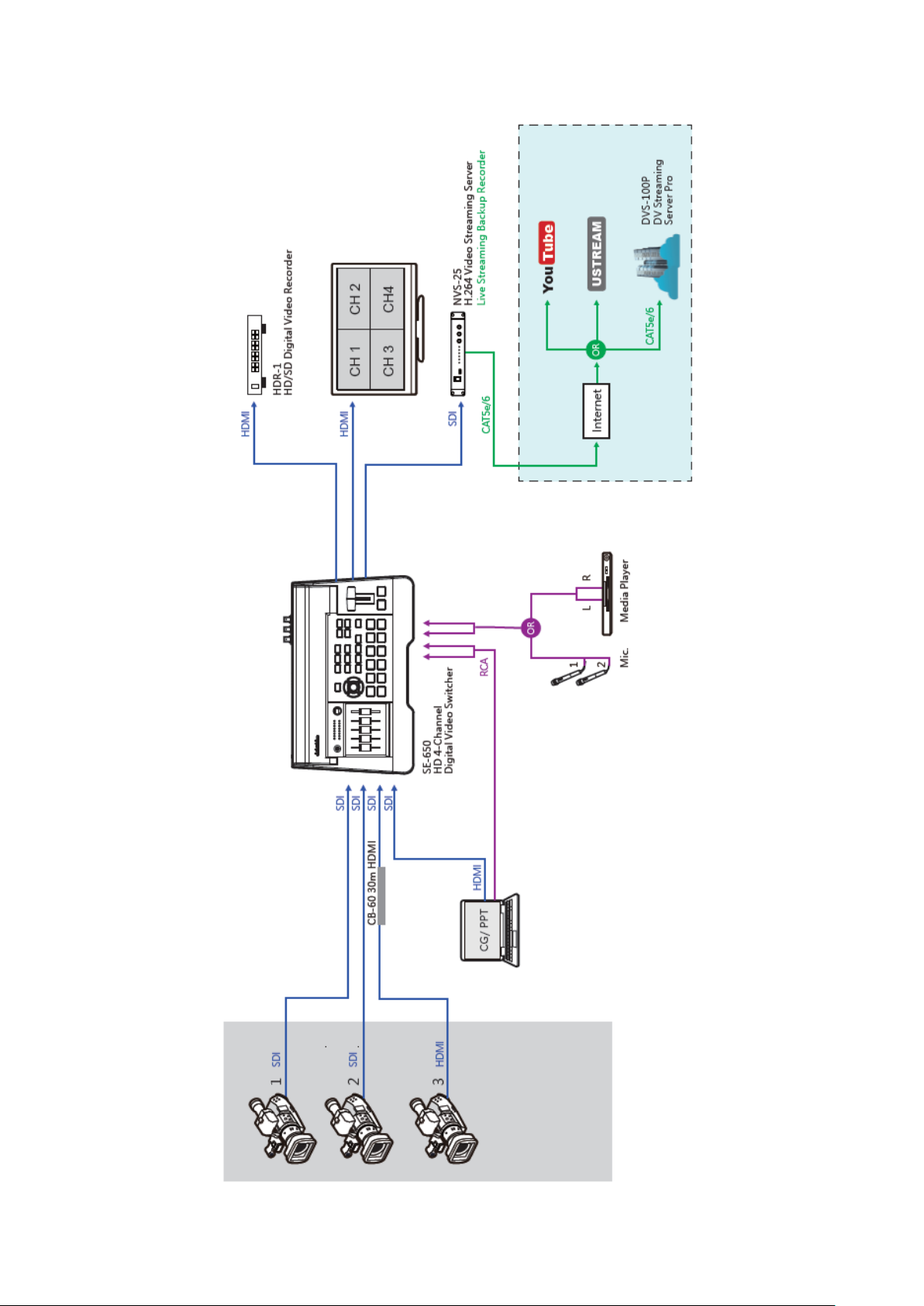
1.2 System Diagram
9
Page 10
Chapter 2 Connections and Controls
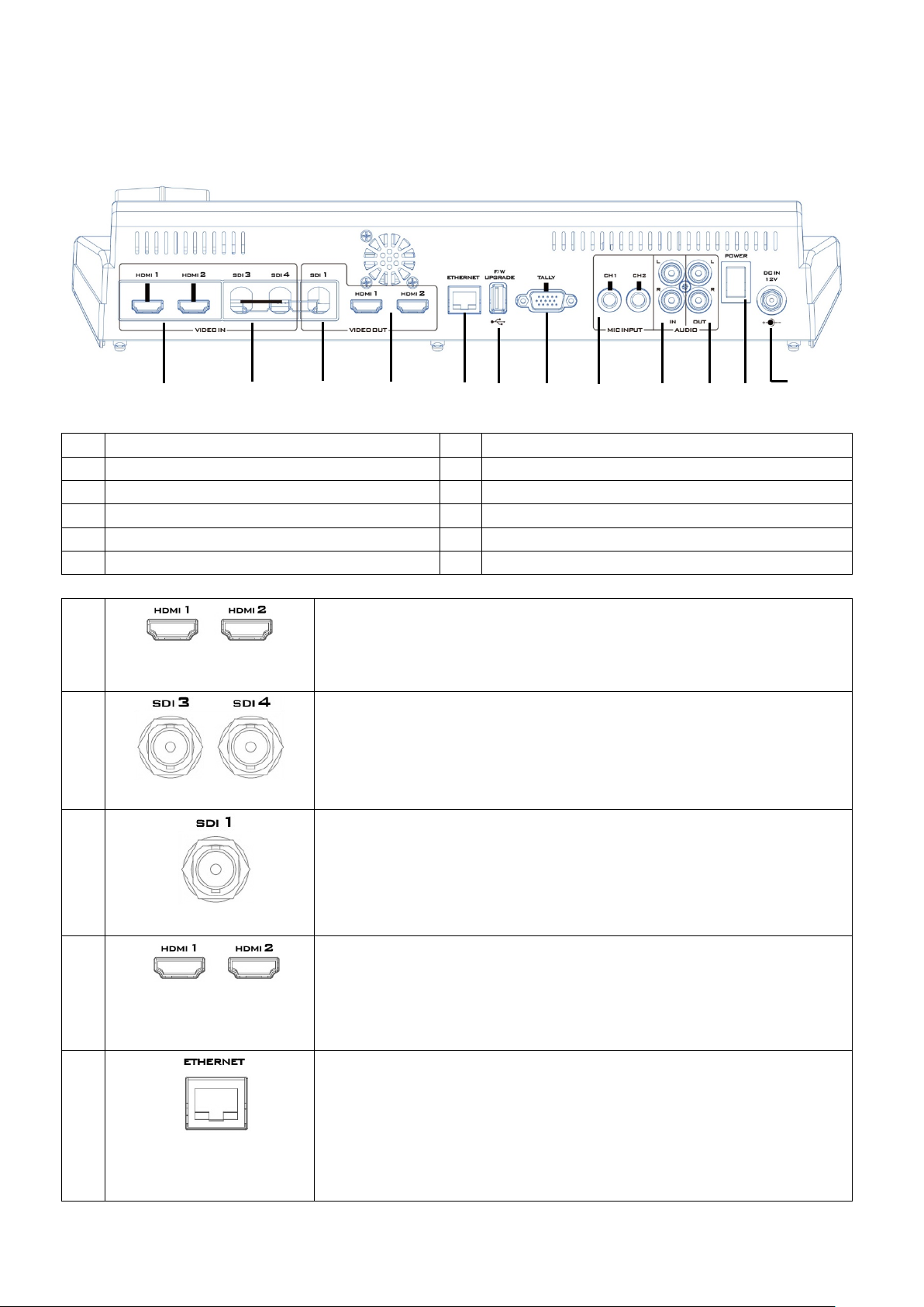
1
HDMI Video Input 1-2
7
TALLY Output Port
2
HD-SDI Video Input 3-4
8
MIC IN – CH1/CH2
3
HD-SDI Video Output 1
9
Audio Input – Stereo RCA (Left/Right)
4
HDMI Video Output 1-2
10
Audio Output – Stereo RCA (Left/Right)
5
Ethernet Port
11
Power Switch
6
USB F/W Upgrade Port
12
DC IN
1 HDMI Video Input 1-2
2 HD-SDI Video Input 3-4
3 HD-SDI Video Output 1
4 HDMI Video Output 1-2
5 Ethernet Port
1
4 5 6 7 8 9 10
12 2 3
11
2.1 Rear Panel
The SE-650 provides two HDMI video input channels for connecting
HDMI video sources.
The SE-650 provides two HD-SDI video input channels for connecting
HD-SDI video sources.
The SE-650 provides an HD-SDI video output channel which can be
connected to an HD-SDI video display.
The SE-650 provides two HDMI video output channels which can be
connected to any HDMI video monitors. HDMI 1 is user assignable
and HDMI 2 outputs Multiview display.
The Ethernet port allows the user to transfer files to and from the
switcher on the PC remotely. See Chapter 3 for details on how you
can utilize this port or perform system setup using this port.
Note: The SE-650 has a default IP address of 192.168.1.101.
10
Page 11
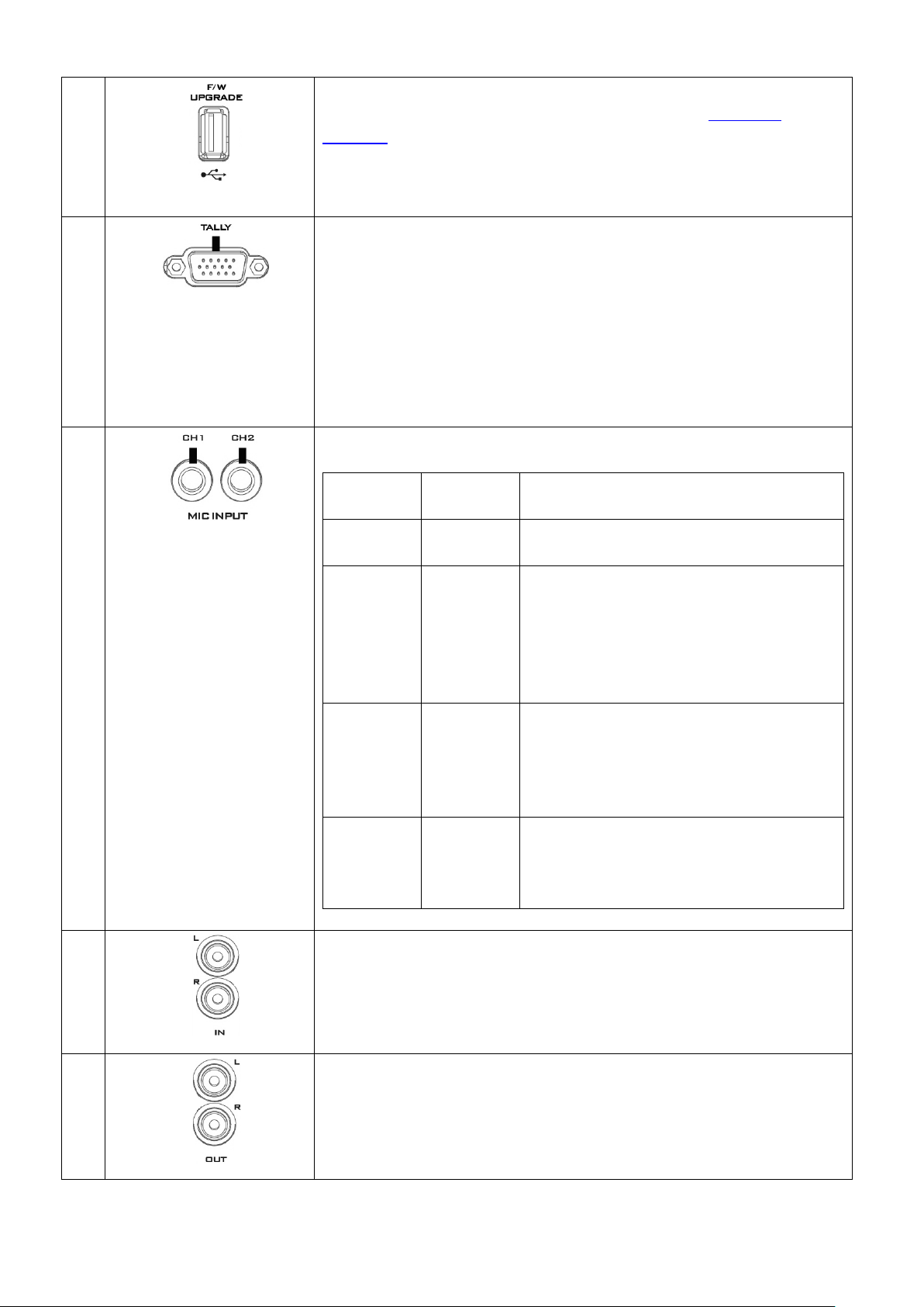
6 USB F/W Upgrade Port
USB port for firmware upgrade. Please refer to the Firmware
7 TALLY Output Port
8 MIC IN – CH1/CH2
Left
Channel
Right
Channel
States
MIC1
MIC2
MIC 1(L) and MIC 2(R) are respectively
connected to left and right channels.
MIC1
Not
When MIC 1 is connected to the left
MIC 1 input signals.
Not
MIC2
When no MIC signal is connected to the
which will thus be grounded.
Not
Not
When no MIC is connected to the two
from being generated.
9 Audio Input – Stereo RCA (Left/Right)
10 Audio Output – Stereo RCA (Left/Right)
Upgrade section for the procedure.
Sends Red, and Green tally signals to each channel.
Red indicates On-Air, and Green indicates next camera source. Tally
output port can connect other Datavideo peripheral devices such as
ITC-100, ITC-200, AM-100 or other monitor models, allowing the
peripheral device to communicate with the SE-650 or send tally
signal to be displayed on the monitor.
Two Channels of unbalanced MIC input.
Connected
channel and MIC 2 is not connected to
the right channel, the right channel
switch will replicate MIC 1 signal onto
the right channel thus both channels are
Connected
left channel and only MIC 2 is connected
to the right channel, MIC 2 signal will
not be replicated onto the left channel
Connected
Connected
channels, the left channel switch will
ground the left channel to prevent noise
Connects unbalanced analog audio source (stereo) for streaming and
recording.
Unbalanced analog audio output (stereo) for monitoring the
selected audio input source.
11
Page 12
11 Power Switch
12 DC IN
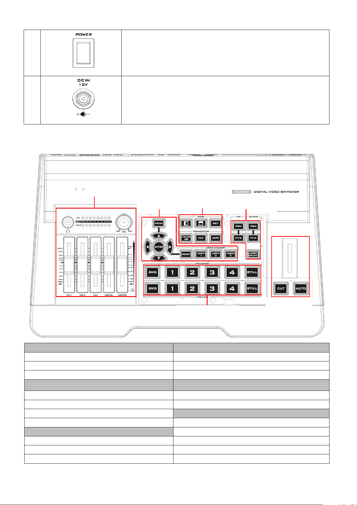
Switcher Settings
Transition Methods
Menu browsing buttons
T-Bar (manual transition)
RESET button
CUT button
User Memory
AUTO transition button
WIPE transition effect selection
Program row
TRANS BG – Background transition
Preview row
MIX Enable/Disable button
Volume Control
WIPE transition effect Enable/Disable
Volume adjustment sliders
PIP/Keyer
Headphone jack
PIP Enable/Disable buttons
Audio meter
Keyer Enable/Disable buttons
Headphone volume control knob
Logo Enable/Disable button
Switcher
Settings
Transition
Effects
PIP/Keyer
Transition
Program/Preview
Volume Control
2.2 Front Panel
Power switch ON/OFF
DC in socket connects the supplied 12V / 19W PSU. The connection
can be secured by screwing the outer fastening ring of the DC In plug
to the socket.
Transition Effects Program / Preview Outputs
12
Page 13
Switcher Keyboard Descriptions
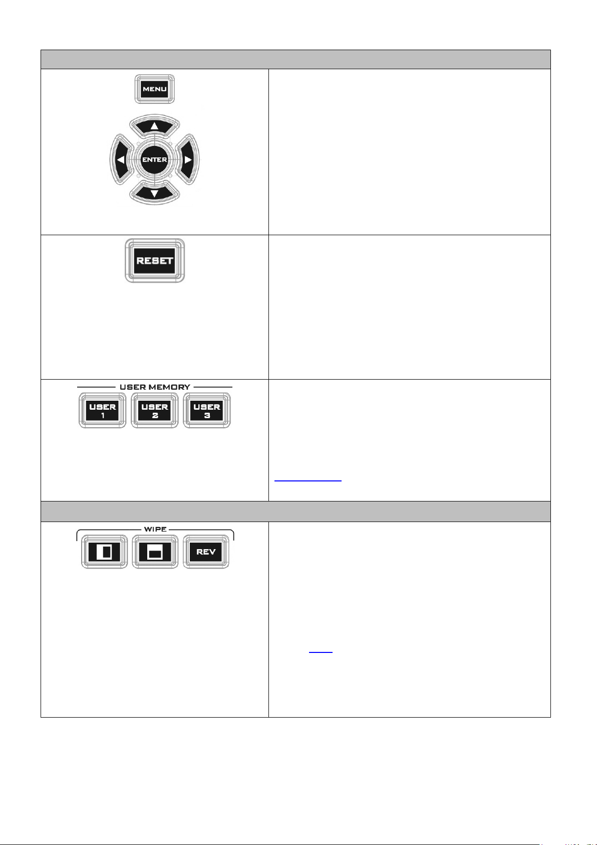
Menu browsing buttons
Press the MENU button to gain access to the menu;
Reset Button
When in Menu Select mode (left hand
will reset all current menu items to their factory
User Memory
Transition Effects
WIPE Transition Effect Selection
use the up/down/left/right arrow buttons to browse
through the menu and press ENTER button to select an
option or MENU button again to exit.
Mode 1 column of the OSD menu), pressing the 'Reset' button
defaults.
Mode 2 - When in a Sub-Menu, pressing the 'Reset'
button will reset the current menu line only.
User Memory buttons 1-3 allow the user to quickly
recall and load previously saved switcher settings with
a single button press. This includes PIP, Keyer and DSK
settings. The switcher loads settings saved to User
Memory 0 as default settings used at boot up. See the
User Memory section for more information.
Each Wipe button consists of black and white colors.
The white represents the current Program image and
the black represents the WIPE-IN image. There are a
total of 2 WIPE presets offered on the SE-650; the
WIPE buttons allow the user to make a selection
directly from the control panel for the first 2 and
remaining 30 WIPE effects are selectable from the
menu (Start).
Pressing the REV button reverses the direction of the
WIPE.
13
Page 14
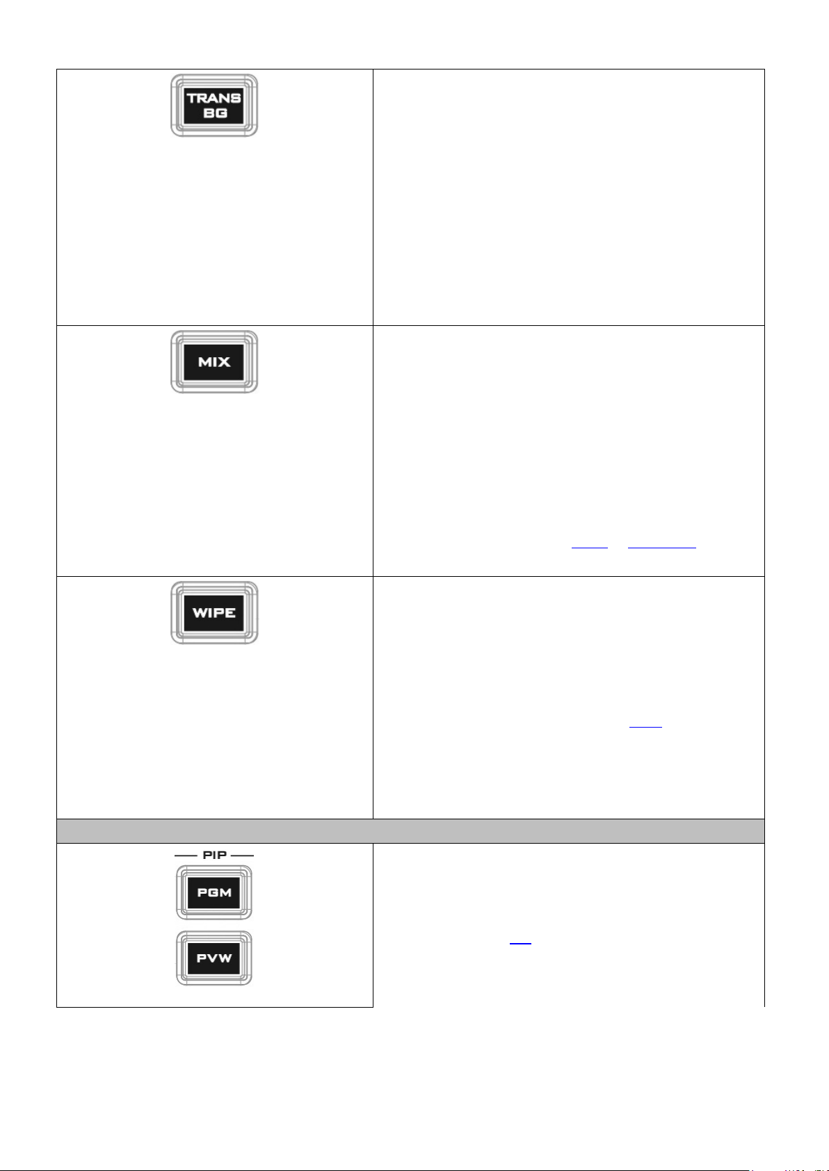
TRANS BG – Background Transition
The TRANS BG button enables Background Transition
MIX Enable/Disable button
WIPE Transition Effect Enable/Disable button
PIP/Keyer
PIP Enable/Disable buttons
PIP PGM: Shows the configured PIP on multiview and
between Program / Preview. This feature is primarily
used in Chromakeyer effect. When enabled,
foreground and background will be switched together
during transition. The background will be locked when
the TRANS BG is disabeld, thus only the foreground is
switched during the transition and the background will
remain unchanged. If you would like to use the
switcher function, please enable the “TRANS BG”
function.
A MIX, also known as a dissolve, is a transition wherein
the Program video is replaced by the Preview video at
a smooth rate, and at the same time. Pressing the MIX
button will enable the MIX transition effect and
automatically disable the WIPE button. To activate the
MIX effect, simply press the AUTO button or move the
T-Bar.
Transition time of the MIX Effect can be configured in
the OSD MENU by selecting Start Transition.
Pressing the WIPE button enables the WIPE transition
effect after which the WIPE transition effect can be
selected. To trigger the WIPE transition effect, simply
press the AUTO button or move the T-Bar.
Wipe transition effect selection, border and position
can be configured in the OSD menu (Start).
Note: When WIPE and MIX buttons are enabled at the
same time, the SE-650 enters the Clip Transition mode.
Picture in Picture puts the selected Sub Video Source in
a window on the Main Program view, with control over
window size and placement. For PIP configuration,
please refer to the PIP section.
PGM outputs.
14
Page 15
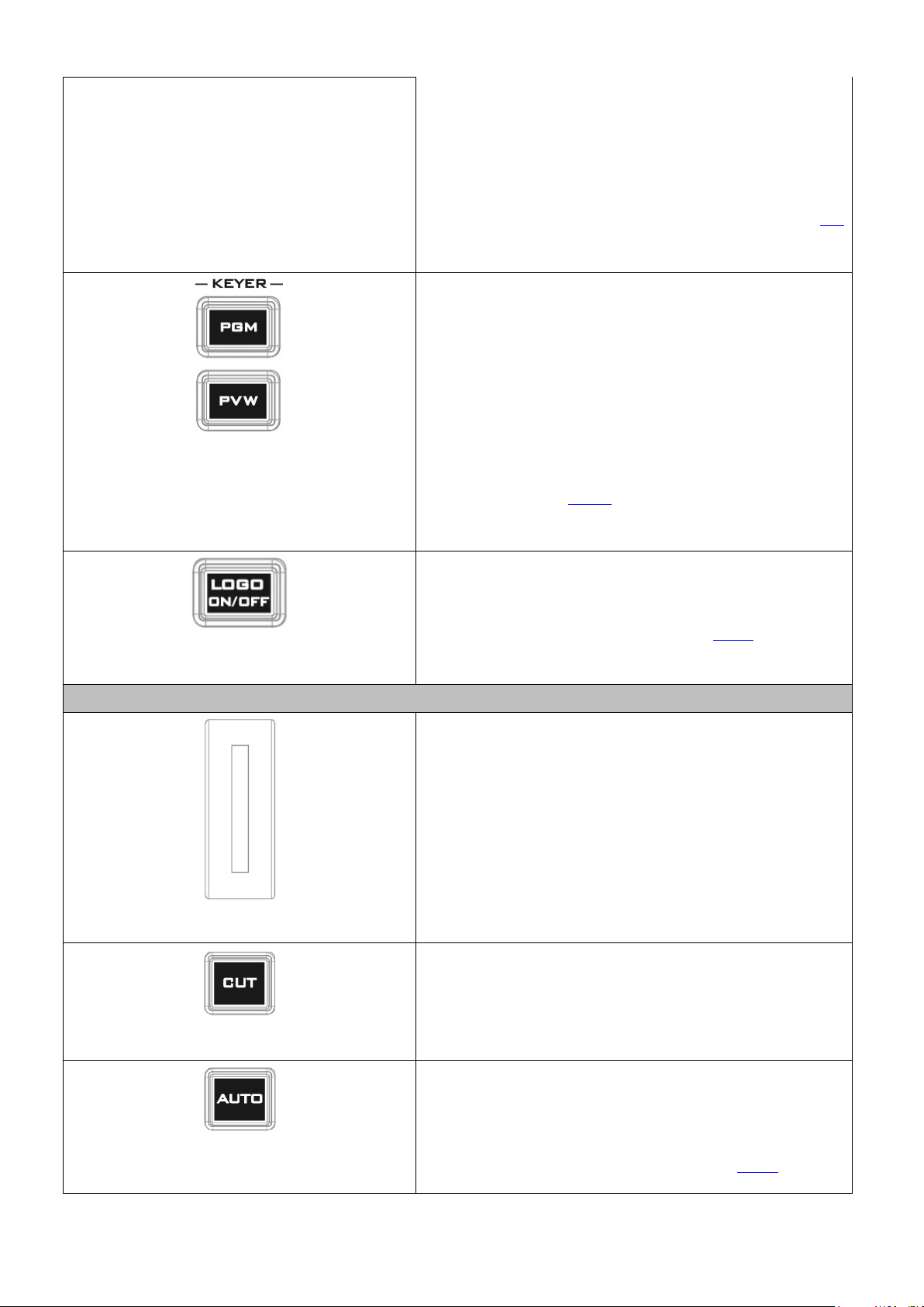
PIP PVW: Shows the configured PIP on PVW and
multiview outputs. Holding down this button also
from the Preview
Note: You are also allowed to apply the chromakey
Keyer Enable/Disable buttons
PVW and multiview
Logo Enable/Disable button
Transition Methods
T-Bar (Manual Transition)
CUT button
mmediate manual
without any
AUTO button
allows selection of the PIP source
Source row. The selected source button will flash.
effect to the PIP window. Please refer to the PIP
section for chromakey configurations.
KEYER PGM: Enables the key (Chroma / Luma / Linear)
on multiview and PGM output
KEYER PVW: Enables Keyer on
outputs. Press and hold this button until the Preview
Source row starts to flash and then select Keyer KEY or
FILL sources from the Preview Source row.
Please refer to the Keyer section for keyer
configurations.
The LOGO ON/OFF button enables the configured Logo
on PVW and PGM outputs. Please configure the logo
image source in the OSD. Refer to the Logo section for
configuration details.
T-Bar is used to manually perform a transition. PVW
and PGM views can be transitioned at your preferred
speed. To include the transition effect, simply press the
WIPE or MIX button, after which the Transition Effect
will be trigger as you move the T-Bar.
Pressing the Cut button performs i
switch between PVW and PGM views
transition effect.
Pressing the Auto button automatically transitions
PVW and PGM views according to the selected speed
and the configured transition effect. The AUTO
transition effect can be configured in the Start option.
15
Page 16
Program / Preview Outputs
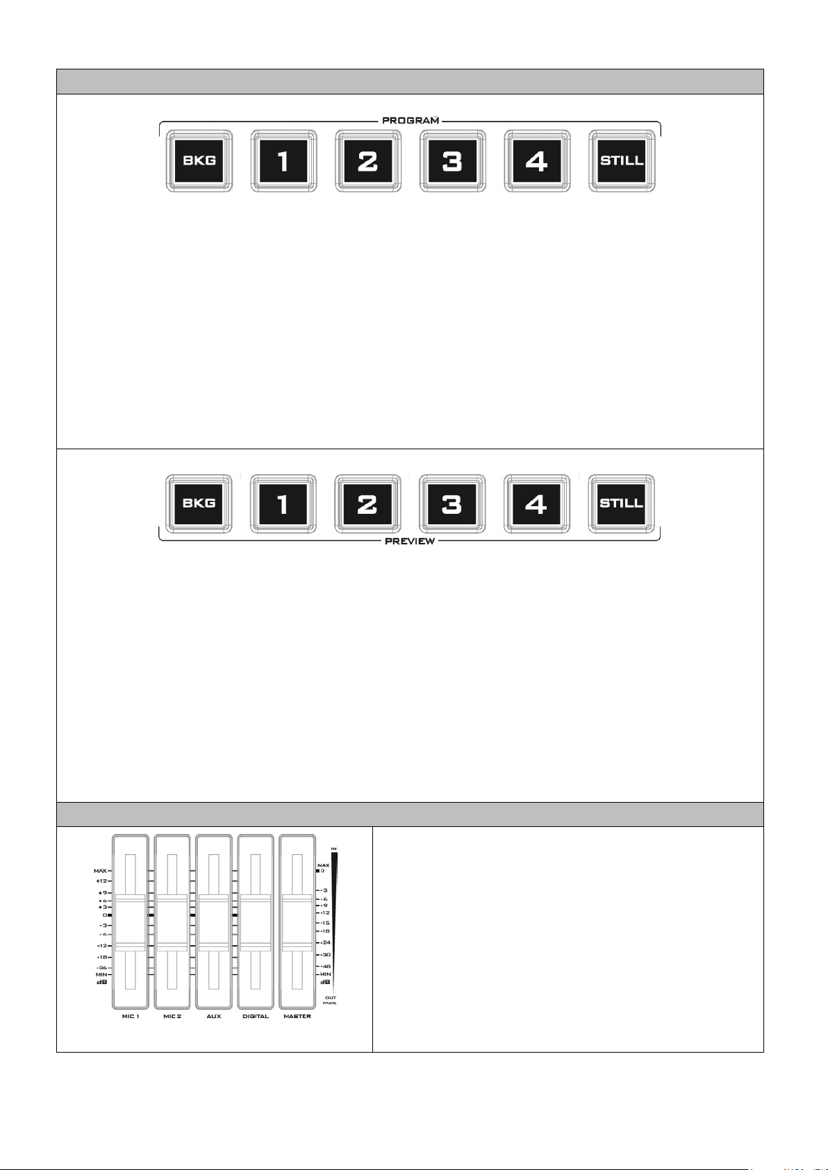
Program Source Row
Preview Source Row
Volume Control
Volume Adjustment Sliders
Pressing the number buttons along the PROGRAM row selects a video source for the PGM view.
BKG button: Pressing the BKG button will switch the background to the Matte background or color
bars.
Still button: Pressing the STILL button will switch the Main Program view to a still picture, which can
be selected in the OSD menu.
Note: Pressing the STILL button repeatedly alternates the Main Program view between Still 1 and Still
2 pictures.
Pressing the number buttons along the PROGRAM row selects a video source for the PGM view.
BKG button: Pressing the BKG button will switch the background to the Matte background or color
bars.
Still button: Pressing the STILL button will switch the Main Program view to a still picture, which can
be selected in the OSD menu.
Note: Pressing the STILL button repeatedly switches the Main Program view between Still 1 and Still 2
pictures.
Sliders to control audio levels for the Main audio mixer.
MIC 1: Unbalanced MIC IN
MIC 2: Unbalanced MIC IN
AUX: RCA audio input (analog)
Digital: HDMI or SDI audio input (digital)
Master: Main audio output
16
Page 17
Headphone Jack
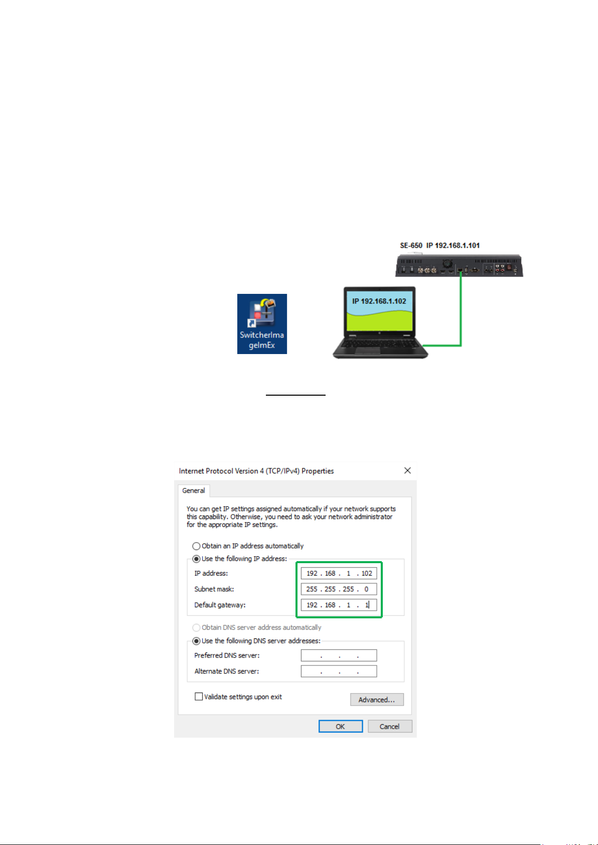
Audio Meters
Audio Volume
(dBV)
-20 -10 -8 -4 0 4 8 10
LED Color
G G G
G G Y Y R
Range (dBV)
-20
-12
-11
-9.5
-8.5
-6.5
-5.5
-3
-2 1 2
5.5
6.5 8 9+
Headphone Volume Control Knob
G: Green Y: Yellow R: Red
Headphones jack accepts a stereo mini jack plug for
stereo headphones. The headphone volume is
controlled by the Headphone volume control knob.
LED style meters, which show the signal strength at the
Main Program Audio Output. The signal measured is
determined by the level set with the Master slider. The
LEDs turn red at +10 dB to indicate clipping distortion.
Headphone volume control knob controls Headphone
level with the MIN representing the minimum volume
and MAX representing the maximum volume.
17
Page 18
Chapter 3 Network Setup
The Ethernet port on the back panel of the SE-650 allows the user to import Still/Clip image or User
memory using the Switcher Image Import/Export software discussed in Chapter 5. This chapter
discusses direct connection between the SE-650 and your Windows computer as well as the remote
setup in detail. Please note that the Switcher Image Import/Export software must be installed on
your Windows-based computer before using this feature.
3.1 Switcher Setup with a Windows Computer
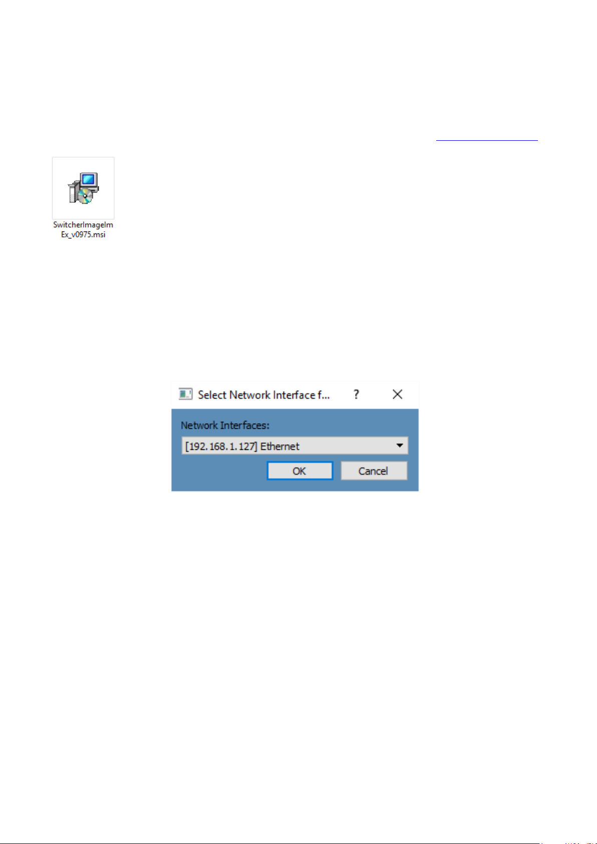
When new from the factory the SE-650 will initially have a static IP address of 192.168.1.101. The
unit can be directly connected to a Windows-based computer using an RJ-45 ethernet cable. The
following set up should allow you to initially configure the unit before moving it to an existing DHCP /
LAN network.
• An RJ-45 Ethernet cable.
• Windows 7/8/10 laptop or PC.
• The Datavideo Switcher Image
Import/Export software.
Instructions
1. First connect the SE-650 and the Windows computer together using an RJ-45 ethernet cable.
2. Turn on the Windows computer and set it to static IP setup within the Windows Network and
Sharing Centre. In our example below the computer is given the following IP settings so that the
computer matches the same IP range as the switcher.
3. Now install the Switcher Image Import/Export software to the computer.
18
Page 19
3.2 Installing the Switcher Image Import/Export software to a Windows Computer
The SE-650 can be connected to a simple IP network and accessed using Windows-based software. If
you have not already set up the SE-650 with a computer then please follow the instructions in the
previous section.
Please download the latest software from the Datavideo SE-650 web page. See: www.datavideo.com
The install executable file [.msi] will be called SwitcherImageImEx_vXXXX.msi
The vXXXX represents the latest version number.
Double click this .msi file then follow the on screen install wizard prompts.
Once installed launch the Switcher Image Import/Export software.
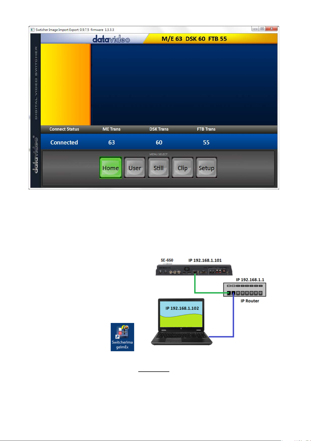
The Switcher Image Import/Export software has a built-in IP finder, which is designed for PC with
multiple Ethernet cards or DHCP network environment. Please note IP finder can only find devices
that are on the same network domain as the PC. If you cannot remember your device IP, please press
the RESET button to restore the default network settings. Upon launch of the Switcher Image
Import/Export software, you will be prompted to select one Ethernet Interface Card.
Once selected, click OK to start the scanning process.
Note: Please make sure the selected interface card is on the same network domain as the SE-650
device.
Once the SE-650 device is found, the software will connect with the switcher hardware over the IP set
up described in the previous section. If the connection is successfully established, on the software
user interface as shown in the diagram below, the Connect Status will show “Connected” (will display
Not Connected if disconnected).
19
Page 20
3.2.1 Router Based DHCP Setup
The computer software can also access the SE-650 over an existing TCP/IP LAN type network. In order
to initially set up the SE-650, you may need the assistance of your local I.T. specialist to help with the
network settings. To help guide you, we have included a simplified network setup example below,
further advice may be available through your dealer locally or your Datavideo regional office.
To create this simple dedicated SE-650 IP network you will need:
• An IP router which can assign/give IP
addresses.
• Two RJ-45 patch leads.
• Windows 7/8/10 laptop or PC.
• The IP router Administrator login and
password.
• The Datavideo Switcher
Image Import/Export
software.
Instructions
1. First connect the router to the SE-650 and the Windows computer using two RJ-45 patch leads.
2. Turn on the Windows computer and set it to DHCP setup within the Windows Network and
Sharing Centre.
3. Now click the Windows start button and run the CMD prompt window.
20
Page 21
4. At the command line > : _ type IPCONFIG and press enter.
5. The DEFAULT GATEWAY number displayed should be the router’s current IP address.
6. Enter the DEFAULT GATEWAY IP address into the address bar of the computer’s web browser.
7. The web browser should display the login window for the router. Enter the router’s login and/or
password.
The login details may be written on a sticker on the router itself or noted in the manual for the
router.
8. Once logged into the router we need to change the router to supply IP addresses in the
192.168.1.xxx range. Use the router’s LAN Setup or Configure LAN option to set the router’s IP
address as 192.168.1.1 and click save / apply.
9. Now reboot the router and power ON the SE-650.
10. Log into the router again using the web browser and the router’s new IP address 192.168.1.1
11. Use the router’s LAN Setup or Configure LAN option again, within this option there should be
another option called Address Reservation or Client List.
12. The two devices connected to the router should be listed here, the computer and the SE-650.
13. The computer, because it is set for DHCP, will already have an IP address automatically assigned to
it in this list.
14. The SE-650 will also be listed with its default IP address of 192.168.1.101 if it is not changed.
15. Click save / apply then reboot the router again.
16. Close the web browser and CMD windows.
17. Now install the Switcher Image Import/Export software to the computer.
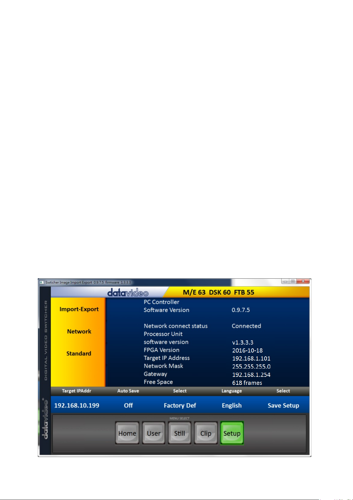
3.2.2 Setting the Target IP Address with the Switcher Image Import/Export Software
Click Setup button in the MENU SELECT pane and the current IP Network settings are shown alongside
the software version.
21
Page 22

If the network settings are wrong then you may not be able to access the SE-650. Always keep a note
of the last IP settings used and change these settings carefully to avoid problems.
Target IP address – This IP address is the location on the local network, or the internet, where the
software can talk to the SE-650. By clicking the Target IP address you can enter a new address, once
entered click Save Setup. The next time the Image Import/Export Software is opened, it will try to
contact the switcher on this new Target IP address.
Network – This option in the yellow menu column allows you to change the network options on the
SE-650. When delivered from the factory the default static IP settings should be:
Addr Mode: Static (a manually set IP address that does not change even after power cycling
the SE-650 unit)
Target IP address: 192.168.1.101
Network Mask: 255.255.255.0
Gateway: 192.168.1.1
DHCP Setup - If the IP set up method is changed to DHCP then each time the SE-650 is started, it may
be given a different IP address by the network. Only use this method if you know how to find the SE650 on the internal IP network. A device on the network (usually a router or server) will automatically
assign an IP address to the SE-650. The other settings such as IP address, Subnet Mask and Gateway
may appear blank within the Switcher Image Import/Export software as these would be
automatically set by network router/DHCP server.
22
Page 23
Chapter 4 OSD Menu
Start
Transition
M/E
60
Type
MIX
Wipe Effects
Wipe
1
Soft
0%
Width
1%
Border
Luma
100%
Sat
80%
Hue
0
Position
X
0% Y 0%
Matte
Luma
100%
Sat
80%
Hue
0
The switcher’s OSD menu allows the user to perform several configurations of image effects, such as
Picture-in-Picture, keyers, downstream keys, still pictures and etc. The user can also configure the I/O
by selecting the Inputs and Outputs options. In addition, in the setup option, the user is allowed to set
the menu color, size, position and language.
The OSD Menu offers the user basic and advanced modes. The basic mode is generally a condensed
version of the advanced menu mode. The following sub-sections will show you the various options
available in these two modes.
4.1 Start
4.1.1 Transition
The Transition sub-option allows the user to set the MIX effect duration, in frames. If the M/E is set to
a value of 50 then the transition will take effect over a period of 50 frames or roughly 2 seconds.
When the AUTO button is pressed, the transition will take the current M/E value defined by the user
setting.
4.1.2 Type
The SE-650 provides three major types of transition effect, which are MIX, WIPE and Clip. Please note
in addition to selecting the transition effect on the OSD menu, you are also allowed to press the MIX
button, WIPE button or press MIX and WIPE buttons at the same time to enable the respective
transition effects.
• If MIX is selected, set the transition duration in the “Transition” sub-option.
• If WIPE is selected, set the relevant WIPE settings in the “WIPE Effects” sub-option.
• If Clip, also known as the Stinger Effect, is selected, please load the clip in the “User Mems”
sub-option.
4.1.3 Wipe Effects
This sub-option allows the user to select the Wipe Effect and configure the wipe’s border softness and
width.
• Wipe – Selection of a WIPE effect from a set of 32 WIPE transition effects.
• Soft – A low value results in a solid edge border and a high value gives a soft diffused border.
• Width – A low value results in a thin border and a high value gives a wide border.
4.1.4 WIPE Border
In this sub-option, the user will be allowed to fine-tune the border color by adjusting the Luma,
Saturation and Hue values.
23
Page 24
Note: Enable the WIPE border by setting the border width (Width) to a value greater than 0. The WIPE
Keyer
Keyer
Chroma
Self
Priority
Top
Keyer Ctrl
Lift
0%
Gain
1.0
Opac
100%
Key Source
Input 1
Fill
Black
CK Setup
CK Auto
Hue
140
Luma
101%
K Range
160
K Fgnd
10%
K Bgnd
90%
Hi-Light
0%
Lo-Light
0%
Bg-Supp
OFF
Mask
Left
0%
Right
0%
Top
0%
Bot
0%
border is disabled when the border width is set to 0.
4.1.5 Position
Position allows the user to adjust the center position of some wipes (e.g Circle & Elipse). X represents
the horizontal position and Y is the vertical position.
Horizontal Position (X)
Positive value moves the wipe center to the right.
Negative value moves the wipe center to the left.
Zero value positions the wipe center at the screen center
Vertical Position (Y)
Positive value moves the wipe center up.
Negative value moves the wipe center down.
Zero value positions the wipe center at the screen center.
4.1.6 Matte
The user can configure the Matte by adjusting Luma, Saturation and Hue in this sub-option.
4.2 Keyer
Keyer of the SE-650 provides the user with the capability of image keying.
Advanced mode options
4.2.1 Keyer
There are three keying modes available: Linear, Luma, and Chroma.
Linear keying mode is usually chosen for sharp images. For non-sharp images, please select Luma
keying. Chroma keying mode allows you to remove the green or blue backdrop from the image.
After the keying mode is chosen, select Self if only one source is enabled for the keyer, which is Key
source. Select Split if two sources are enabled for the keyer, which are Key and Fill sources.
Priority sets the key image to either the top layer or bottom layer.
4.2.2 Keyer Control
“Keyer Control” adjusts lift, gain and opacity of the key image.
Lift adjusts the dark/black areas of the key image.
24
Page 25

Gain adjusts the light/white areas of the key image.
Opac adjusts the transparency of the overall foreground key image.
4.2.3 Key Source
This sub-option allows the user to assign the key source; various options are listed below:
• Bars
• Matte – Set in Start/Matte
• Freeze
• Still 1
• Still 2
• Input 4
• Input 3
• Input 2
• Input 1
• Black
4.2.4 Fill Source
This sub-option allows the user to assign the fill source; various options are listed below:
• Bars
• Matte – Set in Start/Matte
• Freeze
• Still 1
• Still 2
• Input 4
• Input 3
• Input 2
• Input 1
• Black
4.2.5 CK Setup
In this sub-option, the user will be able to find all the parameters needed to perform chromakeying of
the green or blue backdrop.
CK Auto: This function automatically calculates the best Hue & Luma values for the current Keyer
source.
Hue: This parameter adjusts the color of the chroma key. A typical green screen value will be around
120. Blue screen value will be around 240.
Luma: This parameter adjusts the luma value of the chroma key
K Range (Key Range): Key Acceptance sets the range of hues or colors (0 – 360 degrees) that closely
match the background color to be keyed. The user can start with a value of 120 degrees and this value
can be fine-tuned up or down depending on the setup of the green or blue screen studio.
K Fgnd (Key Foreground): Key Foreground adjusts the performance of the chroma key in light or white
areas. Apply more Key Foreground if the light areas are becoming too transparent.
25
Page 26

K Bgnd (Key Background): Key Background adjusts the performance of the chroma key in dark or
P-in-P
P-in-P Src
Input 2
Position
X
-31%
Y
-14%
Size
32%
Border
Luma
100%
Sat
80%
Hue
0
Border
Width
2%
Crop
Left
0%
Right
0%
Size
0%
Top
0%
Bot
0%
black areas. Apply more Key Background if the dark areas are becoming too transparent.
Hi-Light: Hi-light boosts the foreground key in high luminance area.
Lo-Light: Lo-light boosts the foreground key in low luminance area.
Bg-Supp: Background Suppress removes the Luma (Brightness) of the background from the final
image. Bg-Supp turns ON/OFF background suppression.
4.2.6 Mask
The Mask feature basically shrinks the camera image by removing the borders from the final image.
This feature allows the user to configure the Mask in chroma, luma or linear mode.
• Left – Left sets the left edge of the keyer mask.
• Right – Right sets the right edge of the keyer mask.
• Top – Top sets the top edge of the keyer mask.
• Bottom – Bottom sets the bottom edge of the keyer mask.
4.3 P-In-P
Picture-In-Picture (P-In-P) places a sub window on the PGM or PVW screens and allows you to
configure various parameters of the PIP window.
Advanced mode options
4.3.1 P-In-P Source
This sub-option allows the user to assign the P-In-P source; various options are listed below:
• Bars
• Matte – Set in Start/Matte
• Freeze
• Still 1
• Still 2
• Input 4
• Input 3
• Input 2
• Input 1
• Black
4.3.1 Position
The user can adjust the position of the PIP screen by adjusting values of X, Y and SIZE, where X is the
horizontal position, Y is the vertical position and Size is the PIP screen size.
26
Page 27

Horizontal Position (X)
P-in-P Keyer
P-in-P Src
Input 2
Priority
Bot Keyer
Full
Keyer Ctrl
Lift
0%
Gain
1.0
Opac
100%
CK Setup
CK Auto
Hue
110
Luma
80%
K Range
160
K Fgnd
10%
K Bgnd
20%
Hi-Light
0%
Lo-Light
0%
Mask
Left
0%
Right
0%
Top
0%
Bot
0%
Positive value moves the PIP window to the right.
Negative value moves the PIP window to the left.
Zero value positions the PIP window at the screen center.
Vertical Position (Y)
Positive value moves the PIP window up.
Negative value moves the PIP window down.
Zero value positions the PIP window at the screen center.
PIP Window Size (Size)
This parameter ranges from 0 to 100 with 1% being the smallest and 100 being the largest. Therefore
50% would represent a PIP image which is half the size of the background image. 100% would see the
PIP image totally cover the background image unless offset to one side.
4.3.2 Border
PIP border color can be set by adjusting the Luma, Saturation and Hue values. The Width of the
border can also be adjusted. A width of zero (0) will turn the PIP border off.
4.3.3 Crop
The PIP image crop can be adjusted by modifying the following parameters:
• Left – Adjusts the position of the left edge of the PIP image.
• Right – Adjusts the position of the right edge of the PIP image.
• Size – Adjusts the PIP image crop size.
• Top – Adjusts the position of the top edge of the PIP image.
• Bot – Adjusts the position of the bottom edge of the PIP image.
4.4 P-In-P Keyer
P-In-P Keyer basically allows you to remove the green backdrop from the PIP image by adjusting
Chromakeyer parameters. The OSD menu options for P-In-P Keyer are shown below.
Advanced mode options
4.4.1 P-In-P Source
This sub-option allows the user to assign the P-In-P source; various options are listed below:
• Bars
• Matte – Set in Start/Matte
27
Page 28

• Freeze
• Still 1
• Still 2
• Input 4
• Input 3
• Input 2
• Input 1
• Black
Priority sets the key image to either the top layer or bottom layer.
4.4.2 Keyer
The “Keyer” option defines the keyer mode, which is either Chroma or Full mode.
Chroma Mode: Chromakeying on PIP screen
Full Mode: Enabling of full PIP screen mode with the PIP window covering the entire screen.
4.4.3 Keyer Control
Keyer Control adjusts lift, gain and opacity of the key image.
Lift adjusts the dark/black areas of the key image.
Gain adjusts the light/white areas of the key image.
Opacity adjusts the transparency of the overall foreground key image.
4.4.4 CK Setup
CK Auto: This function calculates the best Hue & Luma values for the current Keyer source.
Hue: This parameter adjusts the color of the chroma key. A typical green screen value will be around
120. Blue screen value will be around 240.
Luma: This parameter adjusts the luma value of the chroma key.
Key Range (K Range): Key Range sets the range of hues or colors (0 – 360 degrees) that closely match
the background color to be keyed. The user can start with a value of 120 degrees and this value can be
fine-tuned up or down depending on the setup of the green or blue screen studio.
Key Foreground (K Fgnd): This parameter adjusts the performance of the chroma key in light or white
areas. Apply more Key Gain if the light areas are becoming too transparent.
Key Background (K Bgnd): This parameter adjusts the performance of the chroma key in dark or black
areas. Apply more Key Lift if the dark areas are becoming too transparent.
Hi-Light: Hi-light boosts the foreground key in high luminance area.
Lo-Light: Lo-light boosts the foreground key in low luminance area.
4.4.5 Mask
The Mask feature shrinks the camera image by removing the borders from the final image. This
feature allows the user to configure the Mask in chroma or full mode.
• Left – Left sets the left edge of the P-in-P keyer mask.
28
Page 29

• Right – Right sets the right edge of the P-in-P keyer mask.
Logo
Logo
Luma
Self
Logo Ctrl
Lift
0%
Gain
16.0
Opac
100%
Logo Src
Still 2
Fill
Still 1
Mask
Left
0%
Right
0%
Top
0%
Bot
0%
• Top – Top sets the top edge of the P-in-P keyer mask.
• Bottom – Bottom sets the bottom edge of the P-in-P keyer mask.
4.5 Logo
The user is allowed to use the Logo option to set the logo image signal source. The OSD menu options
for logo are shown below.
See section 5.2 for detailed information on how you can insert the logo to your program.
4.5.1 Logo Image
You may apply linear or luma keyer to the logo image. Linear keying mode is usually chosen for sharp
images. For non-sharp images, please select Luma keying.
After the keying mode is chosen, select Self if only one source is enabled for the logo, which can be
set in the Logo Src option. Select Split if two sources are enabled for the logo, which can be
respectively set in the Logo Src and Fill options.
Note: We do not recommend using the two-source logo (Split) as it requires two physical
connection ports.
An example of Linear Keyer in Self mode: HDMI input port is connected to a Windows notebook
running Datavideo’s CG-200 software.
4.5.2 Logo Control
Logo Control adjusts lift, gain and opacity of the logo image.
Lift adjusts the dark/black areas of the logo image.
Gain adjusts the light/white areas of the logo image.
Opacity adjusts the transparency of the overall foreground logo image.
4.5.3 Logo Source (Logo Src)
Select Logo Source from the list below.
• Bars
• Matte – Set in Start/Matte
• Freeze
• Still 1
• Still 2
• Input 4
• Input 3
• Input 2
29
Page 30

• Input 1
• Black
4.5.4 Fill Source
Select the Fill Source from the list below.
• Bars
• Matte – Set in Start/Matte
• Freeze
• Still 1
• Still 2
• Input 4
• Input 3
• Input 2
• Input 1
• Black
4.5.5 Mask
The Mask feature removes unnecessary borders of the Logo image. The user is allowed to configure
the Mask in Luma or Linear mode.
• Left – sets the left edge of the logo image.
• Right – sets the right edge of the logo image.
• Top – sets the top edge of the logo image.
• Bottom – sets the bottom edge of the logo image.
4.5.6 Logo Insertion
The SE-650 allows the user to place a logo on the video by enabling the logo feature. First of all, create
a 1920x1080 (16:9) logo against a black or white background on a laptop. Once the logo is created,
please follow the steps outlined as follows to insert the logo layer.
Note: If the logo is dark, choose a white background; if the logo consists primarily of bright colors,
choose a black background.
1. Connect the laptop to one of the switcher’s HDMI input ports, for example HDMI Input Port 1.
2. Switch the Program View to the HDMI input 1 (laptop source) and you will see that the logo is
displayed on the Program OUT.
Note: Please make sure PIP, keyer and logo are turned off.
3. Press the MENU button to open the OSD menu on the Multiview display.
4. In the Stills option, browse to Grab Still and select GRAB to grab the logo to a desired location, for
example Still 2.
Note: You are allowed to select a location for Grab/Save/Load Still features. The Stinger (Clip)
feature does not allow you to select the destination, which is fixed to Still 2 only.
5. Browse to Save Still after the logo is grabbed and save Still 2 to a memory location on the
machine.
30
Page 31

Note: To make sure the saved logo will be loaded to Still 2 on the next machine boot, before
Stills
Load Still
Load
Still Num
10
Still 1
Thumbnail
Picture - 1
Thumbnail
Picture
Thumbnail
Picture + 1
Save Still
Save
Still 1
Still Num
10
Grab Still
Grab
Still 1
Freeze
1
Live
2
Live
3
Live
4 Live
rebooting your machine, please first go to Load Still and load the logo saved at Step 5 to Still 2.
6. Browse to the Logo option and select Still 2 as the logo source (Logo Src). Logo Fill should be
assigned to Still 2 as well.
7. In the Logo sub-option, select keyer type as Luma and Self. The recommended Lift is 0% and Gain
is 2.0.
8. After the logo is successfully configured, pressing the Logo ON/OFF button allows you to turn
ON/OFF the logo. Once enabled, the logo will appear on the PVW and PGM views at the same
time.
4.6 Stills
Still allows the user to load images from the memory, save images to the memory, and save the
images captured.
Advanced mode options
See section 5.3 for detailed information on how you can import, export and load the still image to
your program.
4.6.1 Load Still
Upon selecting “Load Still”, the user can then choose the memory location from which the still image
is loaded. The system memory can store up to 500 still images. The following are the destinations to
which the still image can be loaded:
• Still 1
• Still 2
• Input 4
• Input 3
• Input 2
• Input 1
Select “Load” to load the still image to the determined destination.
Image Preview is available below the “Load Still” row. “Image Preview – 1” allows the user to preview
the previous image, “Image Preview” displays the image that will be loaded when “Load” is selected,
and “Image Preview + 1” shows the next image.
Note: The user is allowed to import still picture files. It is recommended to use 24-bit without Alpha
bmp, png and jpg formats.
31
Page 32

4.6.2 Save Still
“Save Still” allows the user to save the still image to a specific memory location. The user should
determine the source of the still image first. The available sources are listed below:
• Still 1
• Still 2
• Input 4
• Input 3
• Input 2
• Input 1
To complete the save, the user can simply select “Save” after determining the memory location.
Note: Pressing the STILL button repeatedly switches between Still 1 and Still 2 pictures.
4.6.3 Grab Still
“Grab Still” function grabs an instant of the video image on the Program view to the destinations
listed as follows.
• Still 1
• Still 2
• Input 4
• Input 3
• Input 2
• Input 1
After determining the destination to which an instant of the video image is captured, simply select
“Grab” to trigger the image grab.
4.6.4 Freeze
“Freeze” function allows the user to select an image source in Input 1-4 windows from one of the four
sources listed as follows:
• Still – A still picture must be loaded to Inputs 1-4 first.
• Freeze – Freezes the videos in the Input 1-4 windows.
• Live – Playback of videos in the Input 1-4 windows.
HDMI 1 video is displayed in the Input 1 window.
HDMI 2 video is displayed in the Input 2 window.
SDI 3 video is displayed in the Input 3 window.
SDI 4 video is displayed in the Input 4 window.
In the following sections, we will show you how to import still images from the PC to the switcher and
load the imported file to the switcher. You are also allowed to export still images from the switcher to
the PC for file editing.
4.6.5 Export/Import Still Images to/from the PC
The switcher’s Image Import/Export software (SwitcherImageImEx_vx.x.x.msi) allows the user to
import still pictures from the PC to the designated Still number of the switcher and vice versa. The
32
Page 33

software installation package can be downloaded from the product page. Features of the
Import/Export software are listed as follows:
- Supported file formats are BMP, JPG, PNG, and PIC.
- Minimum resolution is 1280 x 720.
- Independent exported still pictures in BMP format.
Please follow the steps below to set up the system before installing the software.
• First connect the SE-650 to a Windows computer using an RJ-45 Ethernet cable.
• Since the SE-650 has a default IP address of 192.168.1.101 so the computer should be given
the IP settings that match the same IP range as the switcher.
• Turn on the Windows computer and manually set the IP to 192.168.1.X within the Windows
Network and Sharing Centre.
After the connection is successfully established, the system setup is complete. Now install the
Switcher Image Import/Export utility on the computer.
Installation
1. Download SwitcherImageImEx_vx.x.x.msi from the product page and save it on the local disk.
2. Click the installation file icon to start the Setup Wizard.
3. Click “Next”
4. Click “Install”
33
Page 34

5. When you see the safety warning requesting for permission to allow an unknown publisher to
make changes to the PC, please click “Yes” to continue.
6. Wait for the installation to finish.
34
Page 35

7. After the setup is complete, you will see the following window; click “Finish” to launch
SwitcherImageImEx immediately.
8. After the setup is finished, a shortcut will be created in Start Menu > Programs > datavideo > tools
> SwitcherImageImEx
9. Click SwitcherImageImEx to open the program.
How to use
1. When the program is executed for the first time, it will automatically scan the network and if
multiple network interface cards are found, please select the card that is on the same network as
the device.
35
Page 36

2. If the available device is scanned and found, the connection will be automatically established.
After the connection is successfully established, the Connect Status will show “Connected” (will
display Not Connected if disconnected).
3. After clicking the Setup button, the network information will be displayed in the blue area
(identical to the SE-1200 MU user control interface).
36
Page 37

4. After clicking Import-Export, you will be able to see four options which are Import Still, Import
User, Import Clip and Export.
5. When in Import Still, click a Still number first and enter a location for storing the still. Then click
Import Still again, the interface for selecting picture files will appear. If the selected picture is not
1920x1080 or 1280x720, the following interface will be displayed to allow you to crop or enlarge
the picture.
Crop Size: Select the right crop
Resize Image: You will be allowed to select two sizes, large (1080) or small (720), and zoom the
picture to 1920 x 1080 or 1280 x 720.
OK: Confirm the setting and apply in the switcher.
Cancel: Cancel the selection
Hide: Hide the interface
6. After the right crop is selected or the resolution is correctly configured, the new settings will be
automatically applied to the switcher. To confirm, click the Still button on the MENU SELECT pane
to view the thumbnails.
37
Page 38

Stills
Load Still
Load
Still Num
10
Still 1
Thumbnail
Picture - 1
Thumbnail
Picture
Thumbnail
Picture + 1
In addition to still picture import and export, the user is also allowed to import and export user
memory slots to and from the PC. The Import User has the identical steps; select .mem file to import.
The Import Clip allows the user to import the clip sequential files from the PC. The sequential files are
numbered using the last five characters. Select one file and the system will automatically grab the file
and the rest after that. The supported clip file formats are BMP, JPG, PNG and PIC and the optimal
resolution is 1920 x 1080.
The software supports multiple languages which are English, Traditional Chinese and Simplified
Chinese.
Note: The latest software version can be downloaded from the product page. To update the software,
it is recommended to remove the existing program first. Click “Start Menu > Programs > datavideo >
tools > Uninstall” to remove the program. If the program is not removed, the user will be prompted
that the PC already contains the same program during the reinstallation process. Click “Remove” to
remove SwitcherImageImEx from your computer.
4.6.6 Loading still images
The SE-650 allows the user to load still images saved on the machine to the Multiview screen. Please
follow the steps outlined below to load the still picture.
1. Press the MENU button to open the OSD menu on the Multiview display.
2. Open the Stills menu option as shown below.
38
Page 39

Save Still
Save
Still 1
Still Num
10
Grab Still
Grab
Still 1
Freeze
1
Live
2
Live
3
Live
4 Live
User Mems
Load Mem
Memory
13
Load
Save Mem
Memory
13
Save
Load Clip
Load
Clip 0
Thumbnail
Picture - 1
Thumbnail
Picture + 1
3. In the Load Still sub-option, first select the still picture that you would like to load (Still Num).
The still picture preview is shown in the row right below the Load Still row.
4. Select Load to load the still picture to one of the following destinations:
• Still 1
• Still 2
• Input 4
• Input 3
• Input 2
• Input 1
4.7 User Mems
In this option, the user is allowed to load previously saved settings and save the currently configured
settings.
Advanced mode options
Thumbnail Picture
See section 5.4 for detailed information on how you can import and load clips and user memory
presets to the switcher.
4.7.1 Load Memory
Use the up/down arrow to scroll to the desired memory location and load the saved setting by
selecting “Load”.
Note: The user can also press one of the USER memory shortcut buttons (1-3) on the control panel as
a quick way of loading those previously saved User configurations.
4.7.2 Save Memory
Use the up/down arrow to scroll to the desired memory location and save the current setting by
selecting “Save”.
4.7.3 Load Clip
In this sub-option, use the Up/Down arrows on the physical keyboard of the switcher to browse the
clip files. Once “Load” is pressed, the selected clip will be loaded into the Still 2 window and replace
the previously displayed video or image.
Note: The SE-650 comes with pre-loaded clip files. The SE-650 also allows the user to import
customized clip files. It is recommended to use 32-bit with Alpha png format.
39
Page 40

Preview of clip videos is below the “Load Clip” sub-option. You can preview three clip videos at the
User Mems
Load Mem
Memory
13
Load
Save Mem
Memory
13
Save
Load Clip
Load
Clip 0
Thumbnail
Picture - 1
Thumbnail
Picture + 1
same time. To enable the Clip (Stinger) transition mode, please turn ON the MIX and WIPE buttons
at the same time.
The Stinger Transition Effect is basically an animated effect added during transition of two video
sources. The animated effect is generated by a clip file which consists of a series of sequential files in
bmp/jpg/png/pic formats. In the next few sections, you will be shown how you can load the existing
clip on the switcher, and import the clip to the switcher from the PC.
4.7.4 Loading the existing Clip for Stinger Transition Effect
The SE-650 allows you to generate the stinger transition effect. To do this, the user should first load
the clip saved on the machine to the Still 2 window of the Multiview screen first. Please follow the
steps outlined below to load the clip.
1. Press the MENU button to open the OSD menu on the Multiview display.
2. Move to the User Mems menu option as shown below.
Thumbnail Picture
3. In the Load Clip sub-option, first select the clip that you would like to load. The Clip Preview is
shown in the row right below the Load Clip row.
4. Select Load to load the clip to the Still 2 window. The load progress prompt “Loading Clip
XX/XX ...” will appear. Once loaded, the previously displayed video or image will be replaced.
Note: The load process can take up to tens of seconds.
5. To enable the Clip or Stinger transition mode, please press the MIX and WIPE buttons at the
same time.
4.7.5 Importing the Clip for Stinger Transition Effect from the PC
On the SE-650, you will be able to add a clip between sources. Besides using the existing clips on the
machine, you are also allowed to import your own clip (a series of bmp/png/jpg/pic files) to the SE650 from the PC using the Switcher Image Import/Export utility, which can be downloaded from the
SE-650 product page.
• First connect the SE-650 to a Windows computer using an RJ-45 Ethernet cable.
• Since the SE-650 has a default IP address of 192.168.1.101 so the computer should be given
the IP settings that match the same IP range as the switcher.
• Turn on the Windows computer and manually set the IP to 192.168.1.X within the Windows
Network and Sharing Centre.
• Now install the Switcher Image Import/Export utility on the computer.
• After the utility is installed, click and open the user interface as shown below.
40
Page 41

Click Setup on the MENU SELECT pane
from the yellow
To import a clip from the computer
and if the connection between the SE650 and the PC has been successfully
established, you will be able to see the
network information of your switcher.
Select Import-Export
menu options.
The clip number allows you to select a
location where you can save the clip.
into the SE-650, select Import Clip.
41
Page 42

Note: The Switcher Image Import/Export utility does the conversion from bmp/png/jpg to the .pic
Importing Clips
Click Open to start the clip import. If
After the file conversion, the clip
Note: Clip Conversion and Clip Import have progress dialogs that show progress & number of frames
If the import is cancelled, then the partially imported data will be deleted.
file format. All you need is to give the utility a starting file location and it will give the utility an idea
where to start linking all images up into a sequential animation file.
Select “Import Clip” will open a file
browser window. Browse to the
directory where your clip files are
saved and then select the file at the
zeroth location, in our example on the
right, the file name is frame-000.png.
your files are not the .pic format, they
will be automatically converted to .pic
format by the Switcher Image
Import/Export utility first.
import will then start. After the import
is complete, the progress dialog will be
automatically closed.
done. These dialogs also have a cancel button which allows the user to cancel the import at any stage.
4.7.6 How to Create the PNG Sequence for Stinger Transition Effect
Adobe After Effects is a motion graphics application that can be used for creating the clip file for
stinger transition effect. After the clip file is created, there are two ways to convert the file to the PNG
sequence format readable by the SE-650 switcher in Adobe After Effects. In this section, we will show
you how you can create the PNG sequence for the Stinger transition effect.
Adobe After Effects
1. Click File → Export → Add to Render Queue (or alternatively, you can also click Composition →
Add to Render Queue).
42
Page 43

2. The Render Queue will be displayed in the bottom pane.
3. Click Output Module and on the Main Options window, click the Format dropdown list and select
PNG Sequence.
43
Page 44

4. Click the Channels dropdown list and select the “RGB + Alpha” option.
44
Page 45

5. Click “Output To” and then change the location where your files are rendered. Click Render after
that.
The next section outlines the file conversion procedure using the Media Encoder CC.
Media Encoder CC
1. Click Composition → Add to Media Encoder Queue (or alternatively, you can also click File
Export Add to Media Encoder Queue).
2. Click blue fonts in Format/Preset fields to open the “Export Settings” window.
45
Page 46

3. Click the Format dropdown list and then select PNG.
4. Click the Preset dropdown list and select “PNG Sequence with Alpha.”
46
Page 47

5. Make sure “Export As Sequence” and “Include Alpha Channel” are checked and then click OK.
6. Select “Output File” to choose the render files destination. Click the green button to render.
7. Once completed, the status will display “Done.”
After the sequential files are created and ready, see section 5.4.2 to import the Clip file to the
switcher.
47
Page 48

4.7.7 Important things to note while creating Stinger Transition Effects
When using Datavideo’s SE-650 Multi-Channel Switcher to design and create the Stinger Transition
Effects, in addition to being creative, there are a few things that you need to take into account of.
1. Length limit of the stinger transition animation
The length of a good stinger transition animation should be approximately 0.5 to 2 seconds.
2. The SE-650 allows a maximum of 200 image files in an animation sequence
The number of image files will determine the length of stinger transition time.
3. While designing the animation, it is best to have an image that fills up the entire frame to create
a satisfactory visual effect (please see the images below).
48
Page 49

4.8 Inputs
Inputs
Input 1
Black
0
White
100
Chrom
1.0 Input 2
Black
0
White
100
Chrom
1.0
Input 3
Black
0
White
100
Chrom
1.0
Input 4
Black
0
White
100
Chrom
1.0
Freeze
1
Live
2
Live
3
Live
4
Live
Crosspoint
1
Input 1
2
Input 2
3
Input 3
4 Input 4
5
Still 1
6
Still 2
This feature allows the user to configure the color of the Inputs 1-4. In addition, the user can shuffle
the contents of Inputs 1-4 and Stills.
Advanced mode options
4.8.1 Input 1-4
By selecting the corresponding input (Inputs 1-4), the user will then be allowed to configure the colour
of the input 1-4 by adjusting its Black Level, White Clip and Chroma Gain parameters.
4.8.2 Freeze
“Freeze” function allows the user to select an image source in Input 1-4 windows from one of the
sources listed as follows:
• Still – A still picture must be loaded to Inputs 1-4 first.
• Freeze – Freezes the videos in the Input 1-4 windows.
• Live – Playback of videos in the Input 1-4 windows. When Crosspoint is in its default settings,
HDMI 1 video is displayed in the Input 1 window.
HDMI 2 video is displayed in the Input 2 window.
SDI 3 video is displayed in the Input 3 window.
SDI 4 video is displayed in the Input 4 window.
4.8.3 Crosspoint
Crosspoint gives the user the ability to shuffle the contents of Inputs 1-4 and Stills. In other words, the
user will be able to flexibly assign any of the sources of Inputs 1-4 and Stills to the 5 input buttons (1, 2,
3, 4, and Still) of the Program and Preview rows as desired.
49
Page 50

4.9 Outputs
Outputs
Outputs
Sdi
Pgm
HDMI
MultiV
HDMI
1080P
Audio
Mode
Analog
Level
Auto
Src
Follow
Sdi
On
HDMI
On
Tally Mode
Normal
Multiviewer
AutoNum
Off
Label Inf
Off
Trns Lab
Off
This option allows the user to configure various output settings such as video output, audio output,
and Tally mode.
Advanced mode options
4.9.1 Outputs
In general, there are three output ports (SDI 1, HDMI 1 and HDMI 2) available, wherein SDI 1 and
HDMI 1 can be configured to output one of the following:
• Still 1
• Still 2
• Input 4
• Input 3
• Input 2
• Input 1
• CLN PVW (Clean PVW)
• CLN PGM (Clean PGM)
• PG + DSK (LOGO)
• PV + DSK (LOGO)
• PVW
• PGM
• MultiV (Multi view)
In addition to selecting your output source, you are also allowed to set different resolutions to the
HDMI output port. The two available resolutions are 1080i and 1080p.
Note: Currently there is no configuration option for HDMI 2 as it has been hard coded as Multiview
output.
Please note that when HDMI OUT is set to 1080i, image will be enlarged on the DELL 24” monitor
(Wide Mode = 1:1), exceeding the viewable screen area (overscan). In 1080p and 720p modes, image
overscan and shifts are seen on BENQ 37”/SONY 42” TV.
4.9.2 Audio
In this sub-option, you can turn ON/OFF the embedded audio component at the SDI-out and HDMI-
out.
Mode (Off/Analog): The SE-650 can only accept external audio using the analogue RCA inputs on the
rear panel. By changing the Mode sub-option from Analogue to OFF will mute the incoming RCA audio.
Level (EBU/SMPTE/AUTO): There are two different audio standards available for selection. The user
can either select the EBU or SMPTE standard. By selecting AUTO allows the device to automatically
50
Page 51

detect the audio standard. When the image is 50 Hz, the audio follows EBU standard and when the
Setup
Standard
1080i/50
Save Setup
Menu Mode
Advanced
Menu Pref
Blue
Transp
1
Size
Normal
Menu Pos
Bot
Auto Save
Off
Factory Def
Reset
Reset Names
Language
English
Software
Upgrade
(Available only when the USB storage
is inserted)
s/w: v1.1.1.1
f/w: 2015-08-03
Kbd: v2.15
image is 59.94/60 Hz, the audio follows SMPTE standard.
Src: If “Follow” is selected, the audio will enter Audio follow Video mode, i.e. playback of the audio of
the output video. If “Src” is selected, the SE-650 will play all enabled audio sources.
4.9.3 Tally Mode
Tally output port generally sends two tally signals to each channel. In Datavideo products, Red
indicates On-Air, and Green indicates next camera source.
The SE-650 provides two tally modes:
Normal: If in normal mode, tally lights of all camera sources displayed on the PGM monitor will be
turned ON (Red). These sources include PGM, PIP and Key sources. While transition is in progress, the
next video will be seen on the PGM monitor, tally light of the PVW source camera will thus also be
turned ON (Red).
Audio Mixer: If Audio Mixer mode is selected, tally light of the PGM source camera selected on the
keyboard panel will be turned ON (Red). While transition is in progress, the tally light color will remain
unchanged. The tally light color will only change (Red/Green) after the transition of PGM and PVW
views is complete.
4.9.4 Multiviewer
AutoNum: The Multiview windows can be automatically numbered, and this sub-option turns ON/OFF
automatic numbering.
Label Inf: This sub-option turns ON/OFF Label information. Input label is followed by information
which describes the input as still, live or frozen image.
Trns Lab: This sub-option turns ON/OFF Label Transparency. Once enabled, the background of the
label is then turned from a solid colour to transparent.
4.10 Setup
In the “Setup” menu, the user can change the resolution, switch between full and simplified menu
versions, reset the SE-650 to its Factory Default values, adjust the menu preferences, enable/disable
Auto Save, choose the preferred OSD menu language, upgrade firmware and view the current
firmware versions (Interface, Mainboard and Keyboard).
Advanced mode options
device containing the latest firmware file
51
Page 52

4.10.1 Standard
This option allows the user to choose the appropriate output resolution such as 1080i/50. Once done,
simply select “Save” to confirm the selected output resolution. The available resolutions are
1080i/50/59.94/60, 720p/60/59.94/50.
4.10.2 Menu Mode
The user is allowed to switch between full and simplified menu versions. Select “Advanced” for full
menu display or “Basic” to display a condensed version of the OSD menu.
4.10.3 Menu Preference
In menu preference, the user is allowed to set the menu color, menu transparency level, menu size
and the display position.
Menu color: the available options are blue and grey
Options of Menu Transparency are listed below:
0: No Transparency
1: Background 50% Transparent (buttons not Transparent)
2: All Menu 50% Transparent
Menu Size
The menu size options are:
1. Normal
2. Small (1080i Mode)
3. Large (720p Mode)
Menu Position
Menu Position gives the user ability to select several positions for the Menu area on the Screen. The
current options are Centre, Top, Left, Right and Bottom.
4.10.4 Auto Save
When enabled, your last settings will be automatically saved before the machine is shut down. At the
next boot, the machine will automatically load the last saved settings. In addition, a Still Load will
cause the auto save to occur.
4.10.5 Factory Default
Reset: This option resets the machine to the factory default settings.
4.10.6 Reset Names
This resets the Multiviewer labels (Input 1-4) to their default settings.
4.10.7 Language
The available languages for OSD menu are English, Traditional Chinese and Simplified Chinese.
4.10.8 Software
This option is only available when the USB storage device containing the latest firmware file is
inserted. Select Upgrade to start the firmware upgrade process. Refer to the FIRMWARE UPGRADE
section for more details.
At the bottom of the menu, you will be able to view the version number of the latest firmware
installed.
52
Page 53

Chapter 5 Applications
Keyer
Keyer
Chroma
Self
Priority
Top
Keyer Ctrl
Lift
0%
Gain
1.0
Opac
100%
Key Source
Input 1
Fill
Black
CK Setup
CK Auto
Hue
140
Luma
101%
K Range
160
K Fgnd
10%
K Bgnd
90%
Hi-Light
0%
Lo-Light
0%
Bg-Supp
OFF
Mask
Left
0%
Right
0%
Top
0%
Bot
0%
5.1 Chromakeyer
Performing the configuration steps below will allow you to press KEYER PGM or KEYER PVW buttons
to directly preview the keyer effect.
1. Set up studio equipment including lights and the backdrop (Green/Blue).
2. Press the “MENU” button to open the Keyer Setting Menu.
3. Select “Chroma” and “Split” under the “Keyer” sub-option.
4. Select the camera signal to be chromakeyed under the “Key Source” sub-option.
5. Adjust the left, right, top and bottom values of the “Mask” sub-option to set the chroma key
range based on the green or blue backdrop size.
6. CK Setup
• Key Range defines a color range close to the color (blue/green) of the studio backdrop.
• Key Foreground adjusts the opaqueness and transparency.
• Key Background adjusts the chromakey performance to achieve perfect chromakeying.
• Hi-Light and Lo-Light adjust luma value of the chroma key.
• Bg-Supp removes foreground and background luma (brightness) from the final image.
7. Chroma Key setting is complete.
Remarks: The SE-650 is equipped with auto chromakeying function so if after following the above
steps, a clean chromakeying effect cannot be achieved, you may first use the CK Auto function
under the CK Setup sub-option and then fine-tune other parameters to achieve perfect
chromakeying.
5.2 Logo Insertion
The SE-650 allows the user to place a logo on the video by enabling the logo feature. First of all, create
a 1920x1080 (16:9) logo against a black or white background on a laptop. Once the logo is created,
please follow the steps outlined as follows to insert the logo layer.
Note: If the logo is dark, choose a white background; if the logo consists primarily of bright colors,
choose a black background.
1. Connect the laptop to one of the switcher’s HDMI input ports, for example HDMI Input Port 1.
2. Switch the Program View to the HDMI input 1 (laptop source) and you will see that the logo is
displayed on the Program OUT.
53
Page 54

Note: Please make sure PIP, keyer and logo are turned off.
3. Press the MENU button to open the OSD menu on the Multiview display.
4. In the Stills option, browse to Grab Still and select GRAB to grab the logo to a desired location, for
example Still 2.
Note: You are allowed to select a location for Grab/Save/Load Still features. The Stinger (Clip)
feature does not allow you to select the destination, which is fixed to Still 2 only.
5. Browse to Save Still after the logo is grabbed and save Still 2 to a memory location on the
machine.
Note: To make sure the saved logo will be loaded to Still 2 on the next machine boot, before
rebooting your machine, please first go to Load Still and load the logo saved at Step 5 to Still 2.
6. Browse to the Logo option and select Still 2 as the logo source (Logo Src). Logo Fill should be
assigned to Still 2 as well.
7. In the Logo sub-option, select keyer type as Luma and Self. The recommended Lift is 0% and Gain
is 2.0.
8. After the logo is successfully configured, pressing the Logo ON/OFF button allows you to turn
ON/OFF the logo. Once enabled, the logo will appear on the PVW and PGM views at the same
time.
5.3 Still Images
This section will show you how to import still images from the PC to the switcher and load the
imported file to the switcher. You are also allowed to export still images from the switcher to the PC
for file editing.
5.3.1 Export/Import Still Images to/from the PC
The switcher’s Image Import/Export software (SwitcherImageImEx_vx.x.x.msi) allows the user to
import still pictures from the PC to the designated Still number of the switcher and vice versa. The
software installation package can be downloaded from the product page. Features of the
Import/Export software are listed as follows:
- Supported file formats are BMP, JPG, PNG, and PIC.
- Minimum resolution is 1280 x 720.
- Independent exported still pictures in BMP format.
Please follow the steps below to set up the system before installing the software.
• First connect the SE-650 to a Windows computer using an RJ-45 Ethernet cable.
• Since the SE-650 has a default IP address of 192.168.1.101 so the computer should be given
the IP settings that match the same IP range as the switcher.
• Turn on the Windows computer and manually set the IP to 192.168.1.X within the Windows
Network and Sharing Centre.
After the connection is successfully established, the system setup is complete. Now install the
Switcher Image Import/Export utility on the computer.
54
Page 55

Installation
1. Download SwitcherImageImEx_vx.x.x.msi from the product page and save it on the local disk.
2. Click the installation file icon to start the Setup Wizard.
3. Click “Next”
4. Click “Install”
55
Page 56

5. When you see the safety warning requesting for permission to allow an unknown publisher to
make changes to the PC, please click “Yes” to continue.
6. Wait for the installation to finish.
7. After the setup is complete, you will see the following window; click “Finish” to launch
SwitcherImageImEx immediately.
56
Page 57

8. After the setup is finished, a shortcut will be created in Start Menu > Programs > datavideo > tools
> SwitcherImageImEx
9. Click SwitcherImageImEx to open the program.
How to use
1. When the program is executed for the first time, it will automatically scan the network and if
multiple network interface cards are found, please select the card that is on the same network as
the device.
57
Page 58

2. If the available device is scanned and found, the connection will be automatically established.
After the connection is successfully established, the Connect Status will show “Connected” (will
display Not Connected if disconnected).
3. After clicking the Setup button, the network information will be displayed in the blue area
(identical to the SE-1200 MU user control interface).
58
Page 59

4. After clicking Import-Export, you will be able to see four options which are Import Still, Import
User, Import Clip and Export.
5. When in Import Still, click a Still number first and enter a location for storing the still. Then click
Import Still again, the interface for selecting picture files will appear. If the selected picture is not
1920x1080 or 1280x720, the following interface will be displayed to allow you to crop or enlarge
the picture.
Crop Size: Select the right crop
Resize Image: You will be allowed to select two sizes, large (1080) or small (720), and zoom the
picture to 1920 x 1080 or 1280 x 720.
OK: Confirm the setting and apply in the switcher.
Cancel: Cancel the selection
Hide: Hide the interface
6. After the right crop is selected or the resolution is correctly configured, the new settings will be
automatically applied to the switcher. To confirm, click the Still button on the MENU SELECT pane
to view the thumbnails.
59
Page 60

Stills
Load Still
Load
Still Num
10
Still 1
Thumbnail
Picture - 1
Thumbnail
Picture
Thumbnail
Picture + 1
In addition to still picture import and export, the user is also allowed to import and export user
memory slots to and from the PC. The Import User has the identical steps; select .mem file to import.
The Import Clip allows the user to import the clip sequential files from the PC. The sequential files are
numbered using the last five characters. Select one file and the system will automatically grab the file
and the rest after that. The supported clip file formats are BMP, JPG, PNG and PIC and the optimal
resolution is 1920 x 1080.
The software supports multiple languages which are English, Traditional Chinese and Simplified
Chinese.
Note: The latest software version can be downloaded from the product page. To update the software,
it is recommended to remove the existing program first. Click “Start Menu > Programs > datavideo >
tools > Uninstall” to remove the program. If the program is not removed, the user will be prompted
that the PC already contains the same program during the reinstallation process. Click “Remove” to
remove SwitcherImageImEx from your computer.
5.3.2 Loading still images
The SE-650 allows the user to load still images saved on the machine to the Multiview screen. Please
follow the steps outlined below to load the still picture.
1. Press the MENU button to open the OSD menu on the Multiview display.
2. Open the Stills menu option as shown below.
60
Page 61

Save Still
Save
Still 1
Still Num
10
Grab Still
Grab
Still 1
Freeze
1
Live
2
Live
3
Live
4 Live
User Mems
Load Mem
Memory
13
Load
Save Mem
Memory
13
Save
Load Clip
Load
Clip 0
Thumbnail
Picture - 1
Thumbnail
Picture + 1
3. In the Load Still sub-option, first select the still picture that you would like to load (Still Num).
The still picture preview is shown in the row right below the Load Still row.
4. Select Load to load the still picture to one of the following destinations:
• Still 1
• Still 2
• Input 4
• Input 3
• Input 2
• Input 1
5.4 Stinger Transition Effect
The Stinger Transition Effect is basically an animated effect added during transition of two video
sources. The animated effect is generated by a clip file which consists of a series of sequential files in
bmp/jpg/png/pic formats. In this section, you will be shown how you can load the existing clip on the
switcher, and import the clip to the switcher from the PC.
5.4.1 Loading the existing Clip for Stinger Transition Effect
The SE-650 allows you to generate the stinger transition effect. To do this, the user should first load
the clip saved on the machine to the Still 2 window of the Multiview screen first. Please follow the
steps outlined below to load the clip.
1. Press the MENU button to open the OSD menu on the Multiview display.
2. Move to the User Mems menu option as shown below.
Thumbnail Picture
3. In the Load Clip sub-option, first select the clip that you would like to load. The Clip Preview is
shown in the row right below the Load Clip row.
4. Select Load to load the clip to the Still 2 window. The load progress prompt “Loading Clip
XX/XX ...” will appear. Once loaded, the previously displayed video or image will be replaced.
Note: The load process can take up to tens of seconds.
5. To enable the Clip or Stinger transition mode, please press the MIX and WIPE buttons at the
same time.
61
Page 62

5.4.2 Importing the Clip for Stinger Transition Effect from the PC
Click Setup on the MENU SELECT pane
from the yellow
On the SE-650, you will be able to add a clip between sources. Besides using the existing clips on the
machine, you are also allowed to import your own clip (a series of bmp/png/jpg/pic files) to the SE-
650 from the PC using the Switcher Image Import/Export utility, which can be downloaded from the
SE-650 product page.
• First connect the SE-650 to a Windows computer using an RJ-45 Ethernet cable.
• Since the SE-650 has a default IP address of 192.168.1.101 so the computer should be given
the IP settings that match the same IP range as the switcher.
• Turn on the Windows computer and manually set the IP to 192.168.1.X within the Windows
Network and Sharing Centre.
• Now install the Switcher Image Import/Export utility on the computer.
• After the utility is installed, click and open the user interface as shown below.
and if the connection between the SE650 and the PC has been successfully
established, you will be able to see the
network information of your switcher.
Select Import-Export
menu options.
62
Page 63

To import a clip from the computer
Importing Clips
Click Open to start the clip import. If
After the file conversion, the clip
Note: Clip Conversion and Clip Import have progress dialogs that show progress & number of frames
If the import is cancelled, then the partially imported data will be deleted.
The clip number allows you to select a
location where you can save the clip.
into the SE-650, select Import Clip.
Note: The Switcher Image Import/Export utility does the conversion from bmp/png/jpg to the .pic
file format. All you need is to give the utility a starting file location and it will give the utility an idea
where to start linking all images up into a sequential animation file.
Select “Import Clip” will open a file
browser window. Browse to the
directory where your clip files are
saved and then select the file at the
zeroth location, in our example on the
right, the file name is frame-000.png.
your files are not the .pic format, they
will be automatically converted to .pic
format by the Switcher Image
Import/Export utility first.
import will then start. After the import
is complete, the progress dialog will be
automatically closed.
done. These dialogs also have a cancel button which allows the user to cancel the import at any stage.
63
Page 64

5.4.3 How to Create the PNG Sequence for Stinger Transition Effect
Adobe After Effects is a motion graphics application that can be used for creating the clip file for
stinger transition effect. After the clip file is created, there are two ways to convert the file to the PNG
sequence format readable by the SE-650 switcher in Adobe After Effects. In this section, we will show
you how you can create the PNG sequence for the Stinger transition effect.
Adobe After Effects
1. Click File → Export → Add to Render Queue (or alternatively, you can also click Composition →
Add to Render Queue).
2. The Render Queue will be displayed in the bottom pane.
64
Page 65

3. Click Output Module and on the Main Options window, click the Format dropdown list and select
PNG Sequence.
4. Click the Channels dropdown list and select the “RGB + Alpha” option.
65
Page 66

5. Click “Output To” and then change the location where your files are rendered. Click Render after
that.
The next section outlines the file conversion procedure using the Media Encoder CC.
Media Encoder CC
1. Click Composition → Add to Media Encoder Queue (or alternatively, you can also click File
Export Add to Media Encoder Queue).
2. Click blue fonts in Format/Preset fields to open the “Export Settings” window.
66
Page 67

3. Click the Format dropdown list and then select PNG.
4. Click the Preset dropdown list and select “PNG Sequence with Alpha.”
67
Page 68

5. Make sure “Export As Sequence” and “Include Alpha Channel” are checked and then click OK.
6. Select “Output File” to choose the render files destination. Click the green button to render.
7. Once completed, the status will display “Done.”
After the sequential files are created and ready, see section 5.4.2 to import the Clip file to the
switcher.
68
Page 69

5.4.4 Important things to note while creating Stinger Transition Effects
When using Datavideo’s SE-650 Multi-Channel Switcher to design and create the Stinger Transition
Effects, in addition to being creative, there are a few things that you need to take into account of.
1. Length limit of the stinger transition animation
The length of a good stinger transition animation should be approximately 0.5 to 2 seconds.
2. The SE-650 allows a maximum of 200 image files in an animation sequence
The number of image files will determine the length of stinger transition time.
3. While designing the animation, it is best to have an image that fills up the entire frame to create
a satisfactory visual effect (please see the images below).
69
Page 70

5.5 User Memory
The user memory allows the user to save the current switcher settings to different presets. You will be
able to import/export these memory presets from/to the PC. In this section, we will show you how
you can import and export these user memory presets step by step.
5.5.1 Export/Import User Memory Preset to/from the PC
1. On the Switcher Image Import/Export interface, click Import-Export.
2. After entering the Import-Export option, first select a preset number in the User option and then
click “Import User.”
70
Page 71

3. As soon as “Import User” is clicked, the PC hard disk browser window will open; select a .mem file
to import a user settings file.
4. To export, simply click “Export” and the following window will open; select a preset number to
export the user settings to the PC in .mem file. Click “Export User” to open the file browser window.
5. On the PC hard disk browser window, select a directory in which the .mem file can be saved.
71
Page 72

5.5.2 Loading User Memory Preset
User Mems
Load Mem
Memory
13
Load
Save Mem
Memory
13
Save
Load Clip
Load
Clip 0
Thumbnail
Picture - 1
Thumbnail
Picture + 1
The SE-650 allows the user to load user memory presets saved on the machine to the Multiview
screen. Please follow the steps outlined below to load the user memory preset.
1. Press the MENU button to open the OSD menu on the Multiview display.
2. Open the User Mems menu option as shown below.
Thumbnail Picture
3. In the Load Mem sub-option, first select the Memory Preset that you would like to load
(Memory).
4. Select Load to load the preset settings to the machine.
72
Page 73

Chapter 6 Appendices
PIN No.
Signal Name
Input/Output
Description of Signal
1
Program 1
Open collector output
Tally output of input video Program 1
2
--
--
No Function
3
Preview 1
Open collector output
Tally output of input video Preview 1
4
RCOM (GND)
Ground
Ground
5
Program 4
Open collector output
Tally output of input video Program 4
6
Program 2
Open collector output
Tally output of input video Program 2
7
--
--
No Function
8
Preview 2
Open collector output
Tally output of input video Preview 2
9
GND
Ground
Ground
10
--
--
No Function
11
Program 3
Open collector output
Tally output of input video Program 3
12
--
--
No Function
13
Preview 3
Open collector output
Tally output of input video Preview 3
14
YCOM (GND)
Ground
Ground
15
Preview 4
Open collector output
Tally output of input video Preview 4
Appendix 1 Tally Outputs
The SE-650 has a D-sub 15 pin female tally output port. These connections provide bi-colour tally
information to a number of other Datavideo products, such as the ITC-100 eight channel talkback
system and the TLM range of LCD Monitors. The ports are open collector ports and as such do not
provide power to tally light circuits.
The pin outputs are defined as follows:
73
Page 74

Appendix 2 Firmware Upgrade
Datavideo usually releases new firmware containing new features or reported bug fixes from time to
time. Customers can either download the SE-650 firmware as they wish or contact their local dealer or
reseller for assistance.
This section outlines the firmware upgrade process which should take approximately 10 minutes to
complete.
The existing SE-650 settings should persist through the firmware upgrade process, which should not
be interrupted once started as this could result in a non-responsive unit.
1. Please visit www.datavideo.com and download the latest version of firmware.
2. Save the latest version of firmware in the root directory of the thumb drive.
3. Connect the thumb drive containing the latest SE-650 firmware to the F/W UPGRADE Port.
4. Enter “MENU” and select “SETUP” option.
5. In the “SETUP” option, select “UPGRADE” and press the “ENTER” button to start the upgrade.
6. When the “UPGRADE” sub-option turns to green from red, it indicates that the firmware upgrade
is complete.
7. Reboot the SE-650 to complete the firmware upgrade.
74
Page 75

Appendix 3 Frequently-Asked Questions
No.
Problems
Solutions
1.
Exiting MENU immediately after the
slow button
Basically only the first menu open/exit will
wait about 10 seconds for the system to
restore normal operation. It is expected that
the new version of firmware will correct this
issue.
This section describes problems that you may encounter while using SE-650. If you have any questions,
please refer to related sections and follow all suggested solutions. If problem still exists, please
contact your distributor or the service center.
MENU is opened results in
response.
result in slow button response.
Exiting MENU immediately after the MENU is
opened will NOT result in slow button response
if the machine is ON for at least 30 seconds.
If slow button response is experienced, simply
75
Page 76

Appendix 4 Dimensions
All measurements in millimeters (mm)
76
Page 77

Appendix 5 Specifications
4 sets of input
2 x HD-SDI
2 x HDMI (HDMI 1 is user assignable / HDMI 2 is Multiview)
1 x HD-SDI (User assignable)
Software Update
USB Port
Sync/Reference In/Out
Built-in Genlock (internal)
1080p 50/59.94/60 (HDMI Only)
720p 50/59.94/60
Interfaces
Video Inputs
2 x HDMI
Video Outputs
1 x Stereo RCA (L/R)
Audio Inputs
2 x Mono Microphone
De-embedded Digital Audio (2 CH)
1 x Stereo RCA (L/R)
Audio Outputs
1 x Stereo headphone (Mini Jack with volume control)
Embedded Digital Audio (2 CH / Channel 1 & 2)
Tally Yes / D-Sub 15 male connector
Audio Mixer
Built-in Audio Mixer 6 Channel
Audio LED Meter 2 Rows (Left/Right)
Standards
Supported Input Format
Supported Output Format
1080i 50/59.94/60
1080i/50, 1080i/59.94, 1080i/60
720p/50, 720p/59.94, 720p/60
Internal Processing YUV 4:2:2 10-bit
Mix HD & SD Source HD only
Extras
Keyers 2 Keyers (2 Chroma Keyers); linear and luma keyers
Upstream Keyers 2 (M/E Keyer & PIP)
Chroma Keyers 2 High Quality Chroma Keyers; available in Keyer and PIP
PIP
WIPES
Stills
1 x PIP with adjustable size, position, and crop.
Border with adjustable width & color
32 Wipe Patterns such as Circle and Heart.
Variable border width with Softness control.
Any unused channel can also be used as a still buffer.
Stills can be stored internally
Stinger Transitions Yes
Logo 1
77
Page 78

NOTE
78
Page 79

NOTE
79
Page 80

DATAVIDEO WORLDWIDE OFFICES
Service & Support
It is our goal to make owning and using Datavideo products a satisfying experience. Our support sta is available
to assist you to set up and operate your system. Contact your local office for specific support requests. Plus,
please visit www.datavideo.com to access our FAQ section.
China Shanghai
Datavideo Technologies China Co
601,Building 10,No.1228,
Rd.Jiangchang,
Jingan District,Shanghai
Tel: +86 21-5603 6599
Fax:+ 86 21-5603 6770
E-mail: service@datavideo.cn
China Beijing
Datavideo Technologies China Co
No. 812, Building B, Wankai Center,
No.316, Wan Feng Road, Fengtai District,
Beijing, China
Tel: +86 10-8586 9034
Fax:+86 10-8586 9074
E-mail: service@datavideo.cn
China Chengdu
Datavideo Technologies China Co
B-823,Meinian square,No.1388,
Middle of Tianfu Avenue,Gaoxin District,
Chengdu,Sichuan
Tel: +86 28-8613 7786
Fax:+86 28-8513 6486
E-mail: service@datavideo.cn
China Fuzhou
Datavideo Technologies China Co
A1-2318-19 Room,No.8, Aojiang Road,
Taijiang District,Fuzhou,Fujian,China
Tel: 0591-83211756,0591-83210187
Fax:0591-83211262
E-mail: service@datavideo.cn
China Jinan
Datavideo Technologies China Co
902, No. 1 business building,
Xiangtai Square, No. 129,
Yingxiongshan Road, Shizhong District,
Jinan City, Shandong Province, China
Tel: +86 531-8607 8813
E-mail: service@datavideo.cn
Hong Kong
Datavideo Hong K ong Ltd
G/ F.,26 Cross Lane
Wanchai, Hong Kong
Tel: +852-2833-1981
Fax:+ 852-2833-9916
E-mail: info@dat avideo.com.hk
India Noida
Datavideo India Noida
A-132, Sec-63,Noida-201307,
India
Tel: +91-0120-2427337
Fax:+91-0120-2427338
E-mail: sales@datavideo.in
India Kochi
Datavideo India Kochi
2nd Floor- North Wing, Govardhan Building,
Opp. NCC Group Headquaters, Chittoor Road,
Cochin- 682035
Tel: +91 4844-025336
Fax:+91 4844-047696
Netherlands
Data video Technologies Europe B V
Floridadreef 106
3565 AM Ut rech t,
Th e Netherlands
Tel: +31-30-261-9 6-56
Fa x: +31-30-261-9 6-57
E-mail: info@dat av ideo.n l
Singapore
Datavideo Visual Technology(S) Pte Ltd
No. 178 Paya Lebar Road #06-07
Singapore 409030
Tel: +65-6749 6866
Fa x:+65-6749 3266
E-mail:info@datavideovirtualset.com
Singapore
Data video Technologies (S ) PTE Lt d
No. 178 Paya Lebar Road #06-03
Singapore 409030
Tel: +65-6749 6866
Fa x:+65-6749 3266
E-mail:s ales@dat av ideo.sg
Taiwan
Datavideo Technologies Co. Lt d
10F. No. 176, Jian 1st Rd.,Chung Ho
District, New Taipei City 235, Taiwan
Tel: +886-2-8227-2888
Fax:+886-2-8227-2777
E-mail:service@dat avideo.com.tw
United States
Datavideo Corporat ion
7048 Elmer Avenue.
Whittier, C A 90602,
U.S.A.
Tel: +1-562-696 2324
Fax:+1-562-698 6930
E-mail:sales@datavideo.comE-mail: sales@datavideo.in
United Kingdom
Data video U K Limi te d
Brookfield House, Brookfield Industrial
Estate, Peakdale Road, Glossop,
Derbyshire, SK13 6LQ
Tel: +44-1457 851 000
Fa x: +44-1457 850 964
E-mail: sales@dat avideo.co. uk
France
Datavideo France s.a.r.l.
Cité Descartes 1, rue Albert Einstein
Champs sur Marne 774477 –
Marne la Vallée cedex 2
Tel: +33-1-60370246
Fa x: +33-1-60376732
E-mail: info@datavideo.fr
Please visit our website for latest manual update.
www.datavideo.com/product/SE-650
All the trademarks are the properties of their respective owners. Datavideo Technologies Co., Ltd. All rights reserved 2018
Jan-30.2018
Mar-07.2018
Version : E5
Version : E7
 Loading...