

Page 1
SE-500
SD 4-CHANNEL DIGITAL
DIGITAL VIDEO SWITCHER
VIDEO SWITCHER
SE-500
Instruction Manual
Page 2

1
Table of Contents
FCC COMPLIANCE STATEMENT ......................................................................................................................... 3
WARNINGS AND PRECAUTIONS ........................................................................................................................ 3
WARRANTY ............................................................................................................................................................. 4
STANDARD WARRANTY ......................................................................................................................................................... 4
THREE YEAR WARRANTY ....................................................................................................................................................... 4
DISPOSAL ................................................................................................................................................................ 5
RADIO AND TELEVISION INTERFERENCE........................................................................................................ 6
1. INTRODUCTION .................................................................................................................................................. 7
1.1 PRODUCT OVERVIEW ................................................................................................................................................ 7
1.2 FEATURES ............................................................................................................................................................... 7
1.3 WHAT IS A SWITCHER? .............................................................................................................................................. 8
1.4 WHAT IS A FRAME SYNCHRONIZER? ............................................................................................................................. 8
1.5 POSSIBLE APPLICATIONS ............................................................................................................................................ 8
2. INSTALLATION, CONNECTIONS, SET UP ..................................................................................................... 9
2.1 SOME GENERAL NOTES ON INSTALLATION .................................................................................................................... 9
2.2 POWER UP STATE..................................................................................................................................................... 9
2.3 CONNECTING VIDEO SOURCES .................................................................................................................................. 10
2.4 CONNECTING AUDIO SOURCES ................................................................................................................................. 10
2.5 OUTPUTS AND MONITORS ....................................................................................................................................... 10
2.6 AUDIO MIXER ....................................................................................................................................................... 11
2.7 RS-232 CONTROL .................................................................................................................................................. 11
2.8 TALLY CONTROL ..................................................................................................................................................... 11
2.9 MIDI CONTROL ..................................................................................................................................................... 11
3. QUICK START ....................................................................................................................................................12
3.1 SE-500 FRONT PANEL ............................................................................................................................................ 12
3.2 SE-500 REAR PANEL .............................................................................................................................................. 15
3.3 SELECTING VIDEO INPUT FORMATS AND ADJUSTING AUDIO LEVELS ................................................................................... 17
3.4 USING VIDEO AND AUDIO MONITORS ........................................................................................................................ 17
3.5 CUTTING BETWEEN SOURCES .................................................................................................................................... 17
3.6 DISSOLVING BETWEEN SOURCES ................................................................................................................................ 17
3.7 OTHER TRANSITIONS BETWEEN SOURCES .................................................................................................................... 17
3.8 EFFECTS ............................................................................................................................................................... 18
4. CONTROLS AND OPERATIONS .....................................................................................................................19
4.1 VIDEO SOURCE ...................................................................................................................................................... 19
4.2 COLOR PROCESSOR ................................................................................................................................................ 19
4.3 MENU ................................................................................................................................................................ 21
4.4 AUDIO INPUTS, LEVELS, AND METERS (FADERS, BUS SELECTORS,) ................................................................................... 21
5. USING TRANSITIONS .......................................................................................................................................23
5.1 SELECTING A TRANSITION: FADE, WIPE ...................................................................................................................... 23
5.2 PLAYING A TRANSITION MANUALLY ............................................................................................................................ 23
5.3 PLAYING A TRANSITION AUTOMATICALLY..................................................................................................................... 23
5.4 LIST OF TRANSITIONS AND PARAMETERS (SUITABLE FOR PHOTOCOPYING) ................................................................ 24
6. USING EFFECTS ................................................................................................................................................26
6.1 EFFECTS: QUAD ..................................................................................................................................................... 26
6.2 EFFECTS: SPLIT ...................................................................................................................................................... 26
6.3 EFFECTS: PICTURE IN PICTURE ....................................................................................................................... 27
6.4 EFFECTS: FREEZE ............................................................................................................................................ 27
6.5 BORDER ............................................................................................................................................................ 27
Page 3

2
6.6 BACKGROUND ................................................................................................................................................... 27
7. SAMPLE APPLIC ATIO NS .................................................................................................................................28
7.1 FOUR CAMERA SHOOT: LIVE STAGE PERFORMANCE / SPORTING EVENT ........................................................................... 28
7.2 LIVE CONFERENCE .................................................................................................................................................. 29
7.3 LIVE EVENT MIXING: CLUB VJ / CONCERT .................................................................................................................. 30
7.4 USING SE-500 WITH CG-100 FOR TITLES/GRAPHICS/LOGOS OVERLAY ........................................................................... 31
8. TROUBLESHOOTING .......................................................................................................................................32
8.1 NO POWER ........................................................................................................................................................... 32
8.2 NO IMAGE AT OUTPUT ............................................................................................................................................ 32
8.3 AUDIO CLIPPING .................................................................................................................................................... 32
8.4 FROZEN IMAGE AT OUTPUT ...................................................................................................................................... 32
8.5 IMAGE DISTORTION ................................................................................................................................................ 32
9. APPENDIX ..........................................................................................................................................................33
GLOSSARY OF TERMS .......................................................................................................................................................... 33
TECH NOTES ..................................................................................................................................................................... 36
Video Standards, Formats, and Quality .................................................................................................................... 36
Monitor Calibration (procedures, test patterns/bars) .............................................................................................. 37
SPECIFICATIONS ................................................................................................................................................................. 39
USEFUL ACCESSORIES FROM DATAVIDEO ................................................................................................................................ 41
Datavideo CG-100 ..................................................................................................................................................... 41
Datavideo VGA to DV converter- PPT-100 ................................................................................................................ 41
Datavideo TLM-70D 7” TFT LCD ................................................................................................................................ 42
Datavideo DAC-6 DV to Analog (One way converter) ............................................................................................... 42
Datavideo BAC-03 Balanced-Unbalanced Audio converter ...................................................................................... 43
Bi-Directional IEEE/1394 DV Format Repeater ......................................................................................................... 43
SE500 RS-232 REMOTE CONTROL COMMAND ...................................................................................................................... 44
SE500 MIDI REMOTE CONTROL COMMAND.......................................................................................................................... 49
SE500 TALLY PIN OUTS CROSS REFERENCE ............................................................................................................................ 51
SERVICE AND SUPPORT .....................................................................................................................................52
Disclaimer of Product & Services
The information offered in this instruction manual is intended as a guide only. At all times, Datavideo
Technologies will try to give correct, com plete and suitable information. However, Datavideo Tec hnologies
cannot exclude that some information in this manual, from time to time, may not be correct or may be
incomplete. This manual may contain typing errors, omissions or incorrect information. Datavideo
Technologies always recommend that you double check the information in this document for accuracy before
making any purchase decision or using the product. Datavideo Technologies is not responsible for any
omissions or error s, or for any subs equent loss or dam age caused by using the inform ation contained within
this manual. Further advice on the c ontent of this manua l or on the produc t can be obtained by contacting
your local Datavideo Office or dealer.
Page 4

3
FCC Compliance S t atement
This device complies with part 15 of the FCC rules. Operation is subject to the following two
conditions:
(1). This device may not cause harmful interference, and
(2). This device must accept any interference received, including interference that may cause
undesired operation.
Warnings and Precautions
1. Read all of these warnings and save them for later reference.
2. Follow all warnings and instructions marked on this unit.
3. Unplug this unit from the wall outlet before cleaning. Do not use liquid or
aerosol cleaners. Use a damp cloth for cleaning.
4. Do not use this unit in or near water.
5. Do not place this unit on an unstable cart, stand, or table. The unit may fall, causing serious
damage.
6. Slots and openings on the cabinet top, back, and bottom are provided for ventilation. To
ensure safe and reliable operation of this unit, and to protect it from overheating, do not block
or cover these openings. Do not place this unit on a bed, sofa, rug, or similar surface, as the
ventilation openings on the bottom of the cabinet will be blocked. This unit should never be
placed near or over a heat register or radiator. This unit should not be placed in a built-in
installation unless proper ventilation is provided.
7. This product should only be operated from the type of power source indicated on the marking
label of the AC adapter. If you are not sure of the type of power available, consult your
Datavideo dealer or your local power company.
8. Do not allow anything to rest on the power cord. Do not locate this unit where the power cord
will be walked on, rolled over, or otherwise stressed.
9. If an extension cord must be used with this unit, make sure that the total of the ampere ratings
on the products plugged into the extension cord do not exceed the extension cord rating.
10. Make sure that the total amperes of all the units that are plugged into a single wall outlet do
not exceed 15 amperes.
11. Never push objects of any kind into this unit through the cabinet ventilation slots, as they may
touch dangerous voltage points or short out parts that could result in risk of fire or electric
shock. Never spill liquid of any kind onto or into this unit.
12. Except as specifically explained elsewhere in this manual, do not attempt to service this
product yourself. Opening or removing covers that are marked “Do Not Remove” may expose
you to dangerous voltage points or other risks, and will void your warranty. Refer all service
issues to qualified service personnel.
13. Unplug this product from the wall outlet and refer to qualified service personnel under the
following conditions:
a. When the power cord is damaged or frayed;
b. When liquid has spilled into the unit;
c. When the product has been exposed to rain or water;
d. When the product does not operate normally under normal operating conditions.
Adjust only those controls that are covered by the operating instructions in this
manual; improper adjustment of other controls may result in damage to the unit and
may often require extensive work by a qualified technician to restore the unit to
normal operation;
e. When the product has been dropped or the cabinet has been damaged;
Page 5

4
f. When the product exhibits a distinct change in performance, indicating a need for
service.
Warranty
Standard Warranty
• Datavideo equipment are guaranteed against any manufacturing defects for one year from
the date of purchase.
• The original purchase invoice or other documentary evidence should be supplied at the
time of any request for repair under warranty.
• The product warranty period begins on the purchase date. If the purchase date is unknown,
the product warranty period begins on the thirtieth day after shipment from a Datavideo
office.
• All non-Datavideo manufactured products (product without Datavideo logo) have only one
year warranty from the date of purchase.
• Damage caused by accident, misuse, unauthorized repairs, sand, grit or water is not
covered under warranty.
• Viruses and malware infections on the computer systems are not covered under warranty.
• Any errors that are caused by unauthorized third-party software installations, which are
not required by our computer systems, are not covered under warranty.
• All mail or transportation costs including insurance are at the expense of the owner.
• All other claims of any nature are not covered.
• All accessories including headphones, cables, and batteries are not covered under warranty.
• Warranty only valid in the country or region of purchase.
• Your statutory rights are not affected.
Three Year Warranty
• All Datavideo products purchased after July 1st, 2017 are qualified for a
free two years extension to the standard warranty, providing the
product is registered with Datavideo within 30 days of purchase.
• Certain parts with limited lifetime expectancy such as LCD panels, DVD
drives, Hard Drive, Solid State Drive, SD Card, USB Thumb Drive, Lighting, Camera module,
PCIe Card are covered for 1 year.
• The three-year warranty must be registered on Datavideo's official website or with your
local Datavideo office or one of its authorized distributors within 30 days of purchase.
Page 6

5
Disposal
For EU Customers only - WEEE Marking
This symbol on the product or on its packaging indicates that this product
must not be disposed of with your other household waste. Instead, it is your
responsibility to dispose of your waste equipment by handing it over to a
designated collection point for the recycling of waste electrical and electronic
equipment. The separate collection and recycling of your waste equipment at
the time of disposal will help to conserve natural resources and ensure that it
is recycled in a manner that protects human health and the environment. For
more information about where you can drop off your waste equipment for recycling, please
contact your local city office, your household waste disposal service or the shop where you
purchased the product.
CE Marking is the symbol as shown on the left of this page. The letters "CE" are the abbreviation
of French phrase "Conformité Européene" which literally means "European Conformity". The term
initially used was "EC Mark" and it was officially replaced by "CE Marking" in the Directive
93/68/EEC in 1993. "CE
Page 7

6
Radio and Television Interference
UNITED STATES: The equipment described in this manual generates and uses radio frequency
energy. If it is not installed and used in accordance with the instructions in this manual, it may
cause interference with radio and television reception.
This equipment has been tested and found to comply with the limits for a Class B digital device,
pursuant to Part 15 of the FCC Rules. These limits are designed to provide reasonable protection
against harmful interference in a residential installation. This equipment generates, uses, and can
radiate radio frequency energy, and if not installed and used in accordance with these instructions,
may cause harmful interference to radio communications. However, there is no guarantee that
interference will not occur in a particular installation. If this equipment does cause harmful
interference to radio or television reception, which can be determined by turning the equipment
off and on, the user is encouraged to try to correct the interference by one or more of the
following measures:
1. Reorient or relocate the receiving antenna;
2. Increase the separation between the equipment and the receiver;
3. Connect the equipment into an outlet on a circuit different from that to which the
receiver is connected.
If necessary, consult your dealer or an experienced radio/TV technician for help and/or additional
suggestions. You may find the following booklet helpful: How to Identify and Resolve Radio-TV
Interference Problems, booklet number 004-000-00345-4, prepared by the Federal
Communications Commission. It is available from the United States Government Printing Office,
Washington D.C. 20402.
Note: Changes or modifications not expressly approved by the party responsible for compliance
could void the user’s right to operate this equipment.
Peripherals used in conjunction with this equipment must be connected via shielded interface
cables. Use of unshielded interface cables may result in interference to radio and TV reception,
and may void the user’s right to operate this equipment.
Page 8

7
1. Introduction
Thank you for purc hasi ng Dat a video ’s S E-50 0 D igital Video Switcher. W e hope you will be pleased wit h your
purchase, and with what you can achi eve with this adva nced piece of tech nology. In order to get the most
out of your new switcher, we recommend that you spend some time getting familiar with this manual, as it will
describe in detail all the fu nctions of this unit. In addition, you’ll find s ome useful back ground informat ion on
video and audio, and some detailed examples of ways to use your new switcher.
If you are experienced in video production, you m ay want to immediately take a look at the Quick Start
section.
1.1 Product Overview
The Datavideo SE-500 is an analog input, di gital processing video s witcher. The SE-500 includes 4 groups
of video input (4 x composite & 4 x S-Video), a 3 channel audio mixer, 2 microphone inputs, color cor rec ti on ,
digital video trans ition effects, MIDI control inter face, Tall y out, RS-232 rem ote control inter face…and m any
more professional features.
A built in TBC in each c hannel with YUV 4:2:2 frame s ynchronizer for Composite, and S (Y/C) inputs and
outputs assures stable and high quality video from virtually any source. A built in R.G.B. Color Processor and
a Color Corrector for each video input, with settings that are sav ed, allow you to fine tune your video. The
SE-500 has 15 different digital effects, which include Quad, Split, PIP, Wipes, and Fade.
Additionally, the SE-500 includes a trul y unique feature “Quad Preview.” This previe w output displays both
tally light signals, and next vi deo effects ind icator. The operator can us e one single m onitor to obs erve four
video input sources , camera activities, and video trans ition effects. The SE-500 has all the popular featur es
of many more expensive m ixers and it is extremely compact in si ze. Now you can shoot, mix, and edit, all
within this compact size digital switcher.
With the Datavideo DAC-6 (DV to Composite, Y/C, and Com ponent converter), V P-314 (DV Repeater) , and
10, 20, 40meter DV cables, you may use DV cameras to feed video from up to 200 meters away.
1.2 Features
Digital Processor, high image quality
Four inputs of S-Video (Y/C) and composite video
Quad video preview monitor output with tally & background indicators on screen
Optional YUV output – via breakout cable
Quad, Split, PIP, Wipe, and Fade digital video effects
T-Bar control of digital video effect transitions
Color processor for video correction
RS232 remote control
MIDI control interface
Tally output
Audio mixer with two microphone channels and one auxiliary input
Page 9

8
1.3 What is a switcher?
A switcher is something or someone that allows or facilitates switching. In this case, the switching that
happens is among 4 v ideo and 3 audio sources. And if just switching were the onl y requirement, then this
piece of equipment would be like a row of light switches. But no: to be truly useful in a production
environment, a video s witcher has to provide for num erous ways to go from one video source to anoth er
(transitions), wa ys to adjust the look of the v ideo (color processor and sp ecial effects), to deal wit h audio,
and to keep the whole thing synchronized, looking good.
1.4 What is a frame synchronizer?
A frame synchroni zer is a digita l device that stor es a fram e of video in its m emory and rele ases it at a very
precise moment. T hese little devices are ess ential if you want to mak e a seamless switch from one video
source to another. If the s ources you are switchi ng between ar e not s ynchroni zed with each oth er, the vide o
image falls apart at the transition moment, and the result is not pretty.
The SE-500 has a f ull f rame s ynchr oni zer (also k nown as a t im e base cor rector o r T BC) at its Mai n and Sub
Source inputs in each channel (4 Total) to insure switches without distortion and smooth, well-regulated
video at its output. In add ition to its digit al memor y, a TBC also has contro ls that affec t the look of the video
that passes through it. These controls are known as processing amplifiers, or proc amps; they control
brightness, contrast, color, and tint, though these may have different names in different applications.
For more information on some of these technical aspects, see the Appendix Tech Notes
.
1.5 Possible applications
You may already have some uses in mind for the SE-500. There’s a real good chance that by browsing
through this manual, you will find s ome applicat ions you didn’t think of or ex pect. Tak e a look at the
Applications section; we describe 3 sample uses for the SE-500: Four Camera Shoot (Live Stage
Performance/Sporting Event), Live Conference, and Live Event Mixing (Club VJ/Convert).
Sample
Page 10

9
2. Installation, Connections, Set up
2.1 Some General Notes on Installa t ion
There are a fe w other thi ng s to be a ware of when you are installing and integrating the SE-500. Please make
sure you have read the Warnings and Precautions
The SE-500 sends an d receives analog signals except the RS-232, MIDI, and Tally. You need to be aware
that cable lengths, impedance, c rossing power cords , and adaptors might interfere with video transmis sion.
The cautions below, with the excep tion of physic al damage, wi ll give you the general idea about cabli ng for
analog video or audio.
It is quite possible t hese da ys to buy whatever cable length and connector you need f or your set u p. Not so
long ago, they had to be assem bled individually wit h wire strippers an d solder, but no w you can easil y find
them in most electro nics and vi deo suppl y stores. W e strongly recom mend you use analo g video and audio
cables that are roughly the right length to connect between components. The longer the cable, the more
noise and deterioration of the video signal can be introduced . We strongly recommend that you c heck the
integrity of each ana log cable before installati on by using a contin uity tester (availab le from most electronic
and video suppl y stores). Cabl es can g o bad over time, with use, b y someone walk ing on them , carts r olling
over them, or even f or no apparent ly good reason. It will happen eventua lly. Have a continuity tester han dy
and save yourself some troubleshooting headaches.
Make sure you don’t r un video/audio ca bles and po wer lines together, on top of each o ther, or across each
other. This is another good way to introduc e noise and signal degradation.
Cable connectors will e ventuall y become dirty or oxidatio n will start. T he dirt can cause a ba d connection or
introduce noise in the s ignal. Get some electrical contac t cleaning products, such as those m ade by Caig
Labs (www.caig.com), and use them regularly to avoid problems.
Use adaptors if you must, but keep in mind that each connector is on e more accident waiting to ha ppen, one
more place the signal can be degraded or broken.
Finally, for som e interesting and entertaining exam ples of how to connect and i ntegrate the SE-500 into a
variety of set ups, take a look at the brief Quick Start and the more in depth explanations in
Applications.
section.
Sample
2.2 Power up State
When you first pow er up the SE-500, you will need to check each channel’s connection and s et the audio
levels. All the setting will be retained except color bar output, see “MENU
At power up, channel 1 will be the selected Ma in V id eo So urc e a nd c han ne l 2 will be the selected S ub Vi de o
Source.
Settings that are ret ained a re: color corr ection set tings; r emote contr ol setting; transiti on setting; video ef fect
setting and background color.
”.
Page 11

10
2.3 Connecting Video Sources
S-Video
¼ Stereo Jack
There are two types of plugs used for video signals on the SE-500: BNC, and S-video.
BNC connectors look like this on the cable end. The connector slides over the connector on
the SE-500 and is loc ked in place with a push in a nd c l ockwise turn. The big virtue of these
connectors, which are the standard for almost all professional video applications, is that
they lock in place and cannot be accidentally dislodged.
S-video plugs (also known as Y/C) have 4 tiny pins in them, which carry a separated Y
(luminance) and C (chroma) video signal and provide a much better quality video signal
than composite. These plugs have a tiny bar in them to assure correct alignment in the
socket. They need t o be pressed firmly in place, but very carefully, as the little pins can
bend easily. Align plug and socket and push straight in, firmly.
BNC
2.4 Connecting Audio Sour ce s
The SE-500 uses 2 kinds of plugs for audio connections: RC A and 1/4 inch jack plugs. There are lots of
different names for these plugs. Fortunately for us all, the y are not easily confused in the size and sha pe
departments, so we’ll show you some pictures.
RCA plugs (also sometim es known as phono plugs, cinch, or tulips) are used
for line level audio, such as the connections between a CD pla yer and amp.
The SE-500 uses these in stereo pairs, white for left and red for r ight, at the
audio input and output sections.
1/4 inch jack plugs go t their nam e, som e sa y, becaus e the y used to be us ed to
manually patch together phone lines in the o ld central switc hboard days. The y
come in mono and s tereo configurations:
the plug, the stereo has two. The SE-500 uses a mono plug on MIC CH1 and mono
plugs for MIC CH2.
If you need to use balanced audio inputs or outputs, for low impedance
microphones or connect ions with other prof essiona l au dio gear, you nee d to use
an impedance m atching device to convert low to high impedance (and/or vice
versa). For example Datavideo BAC-03
the mono has one dark band around
.
RCA
¼ Mono Jack
2.5 Outputs and Monitors
Your particular set up and application for the SE-500 will determine what video and audio devices you
connect to the o utpu ts . T ak e a l ook at the Sample Applications
the SE-500 are very high quality, keep in mind that the vide o quality of the various form ats, in descending
order, goes like this: SDI (serial digital), Y.U.V. (analog component), DV, Y/C (S-video), and composite.
Audio outputs are all line level, suitable for connecting to an amp, VCR, or video projector (for example).
for some ex am ples . While all the outputs of
Page 12

11
We can’t stress enough t he im port ance of good monitoring systems. If something doesn’t l ook or sound r ight
Connecting a Datavideo TLM-70D 7” TFT LCD for
at the last stage of the s ignal path, t he Main ou tput, it c an only be eas ily correc ted if you can pinpoi nt where
in the signal path the prob lem is being introduced.
Certain set ups will b enef it great l y by being able to
monitor the video of each input channel, as well as
the Main output. High quality headphones allow
you to hear the audio with far fewer intermediate
steps and far more accuracy, thanks to the
Headphone contro l on the front panel, than going
through an amp and speakers. We suggest both
methods of monitorin g, and listening to the s ound
through a video monitor’s speaker s is also a g ood
idea. Needless to say, if you are outputting to a
record deck, you sh ould be able to eas ily monitor
the output of that device as well.
preview video monitoring, page 41.
2.6 Audio Mixer
An Audio Mixer with two mono microphone inputs and stereo Aux input allows you to adjust and
balance the volume from various audio sources.
2.7 RS-232 control
The RS-232 Control Port enables control of the SE 500 from a PC or other device thru the RS-232 port.
Connects to PC RS-232 se rial interface for rem ote controlled by PC application s oftware. Refer to the
Appendix detail of RS-232 Remote Control Protocol
.
2.8 Tally control
The tally output allows you to s end out t all y light si gnals . Ref er to the App endix detai l of Tally Pinouts’
Cross Reference.
2.9 MIDI control
Connects to other MIDI de vices, such as MIDI k eyboard, and elec tronic piano. Refer to the Appendix
detail of MIDI Control Protocol
.
Page 13
12
3. Quick Start
8. Video Effect: Freeze
1
2
3
4 5 6
11
7
8
9
15
10
12
14
13
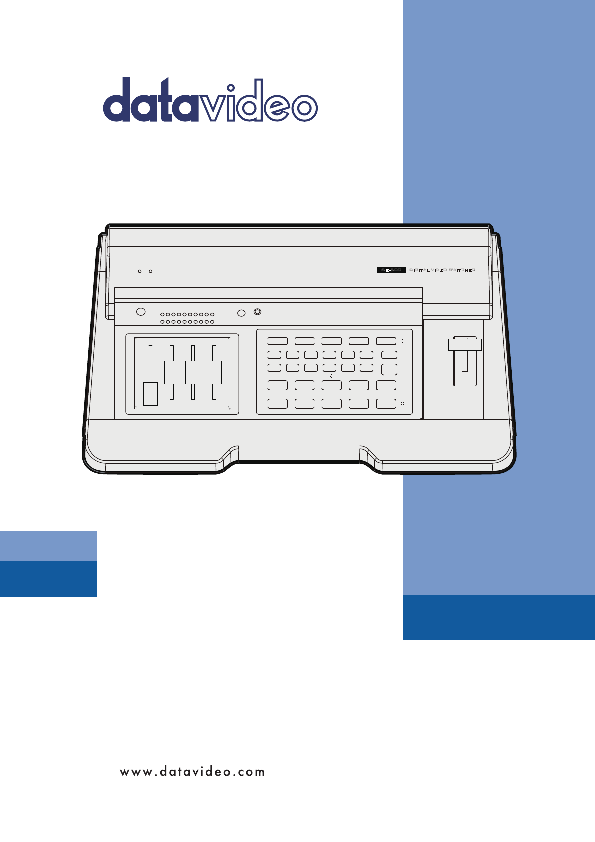
3.1 SE-500 Front Panel
1. Audio faders
2. Headphone
3. Audio meters
4. Headphone Volume Control
5. Video Effect: Quad
6. Video Effect: Split
7. Video Effect: PIP
9. Background color selection/Menu
10. Border On/Off
11. T-Bar
12. Transition Effect preview
13. Main Video Source selectors
14. Sub Video Source selectors
15. Transition mode selectors
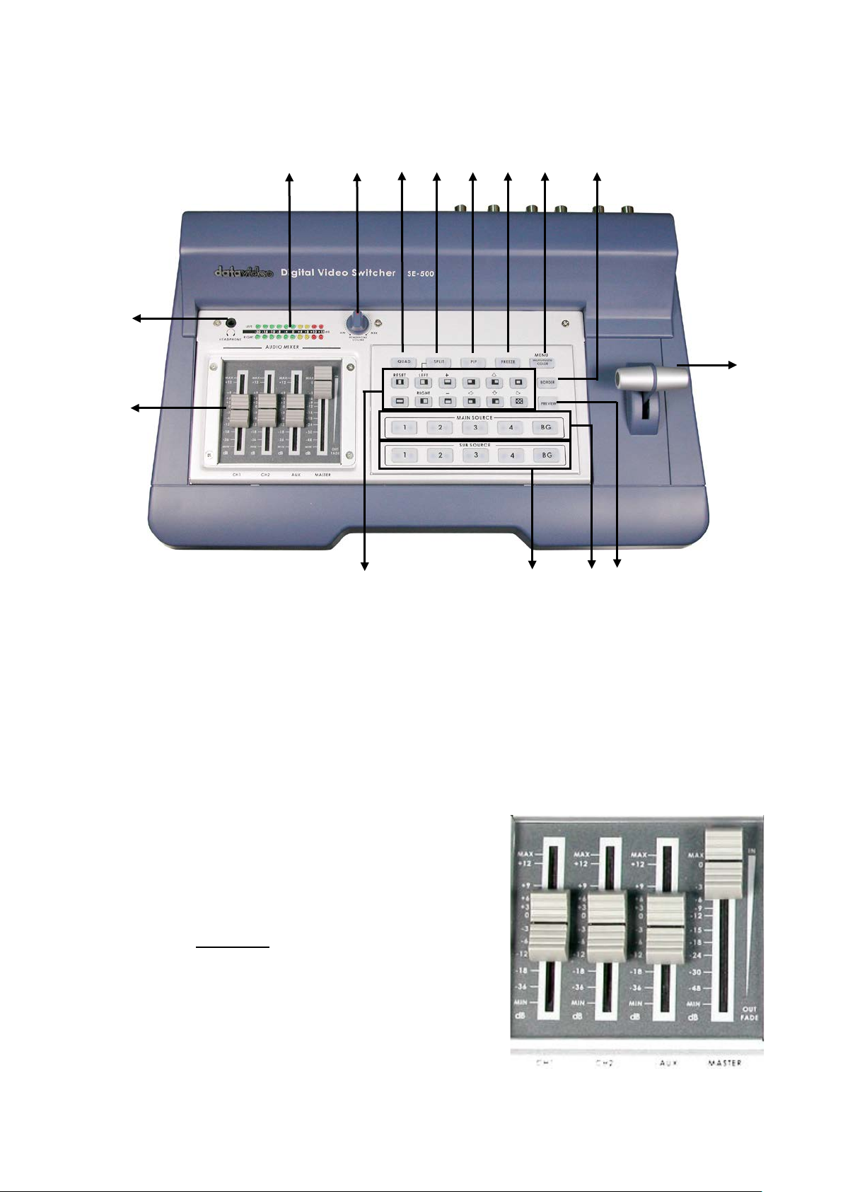
1. Faders: slider s to control a udio levels for the Main audio
output mix. Thes e Audio Level pots are the first stage in
the audio signal path. Analog audio comes in through
the 1/4 inc h pho no jac k and RCA conn ectors on t he r ear
panel see Rear Panel
.
Page 14
13
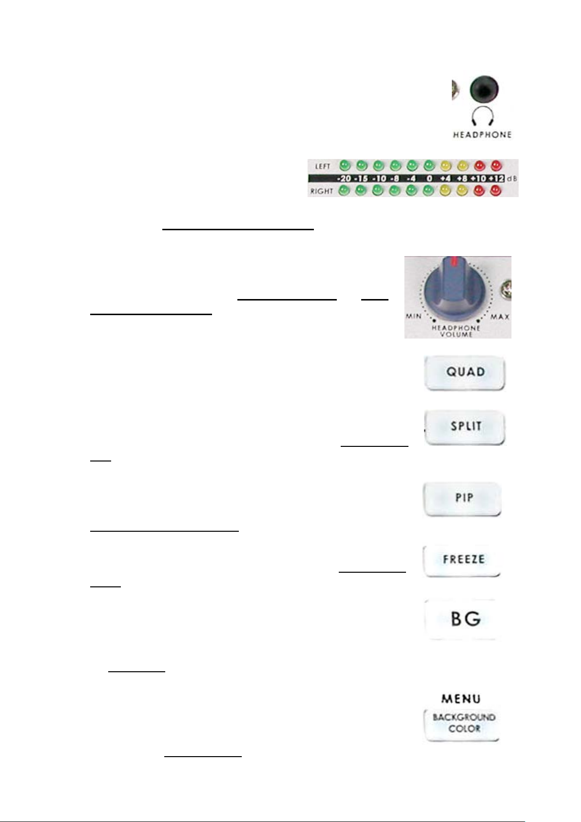
2. Headphones jack: accepts a stereo m ini jack plug for stereo headphones. The
headphone volume is controll ed b y the Headph one volume control (4.).
3. Audio Meters: LED style meters, which show
the signal strength at the Audio Output. The
signal measured is determined by the levels
set with the Faders (1.). The LEDs turn red at
+10 dB to indicate c li ppi ng distor ti on. For more
information, see Audio Inputs, Levels, and Meters
4. Headphone v olume control: controls Headphone le vel and signal(s)
present at the Head phone jack (2.). Level is controlled b y the rotary
knob. For more inf ormation, see Outputs and Monitor and
Inputs, Levels, and Meters.
.
Audio
5. Quad Video Effect: combines four different input sources into one
single output on program monitor.
6. Split Video Effect: split the selected Sub Video Source and the Main
Video Source into left and right ha lf size video screen . Use left and right
function key to swap sides. For more information, see
Split.
7. Picture i n Picture: puts the selected Su b Video Source in a window on
the Main Video Source, with control over window size and placement.
Used in conjunctio n with t he B order k e ys (10.) For m ore infor m ation, see
Using Effects: Picture in Picture
8. Freeze Video Effect: will grab the last field from the Main video output
and hold it as a still image. For more information, see
Freeze.
9. Background: When Background is selected in either the Main or Sub
Video Source (13, 14.), and the button is pressed (and the LED is lit
except with black color background), repeated presses of the color button
cycle through the 8 possible solid backgrounds. For more information,
see Background
.
.
Using Effects:
Using Effects:
10. Menu: Press and hold the button “BACKGROUND COLOR” for 2
seconds or more, a menu will pop up. You are able to change the
camera settings, which include Brightness, Contrast, color, Tint (NT SC
only), 0 or 7.5 IRE, YU V or S-video out, and color bar output. For more
information, see Color Processor
. Press it again and you can change
Page 15
14
output format, MIDI control, and color bar output.
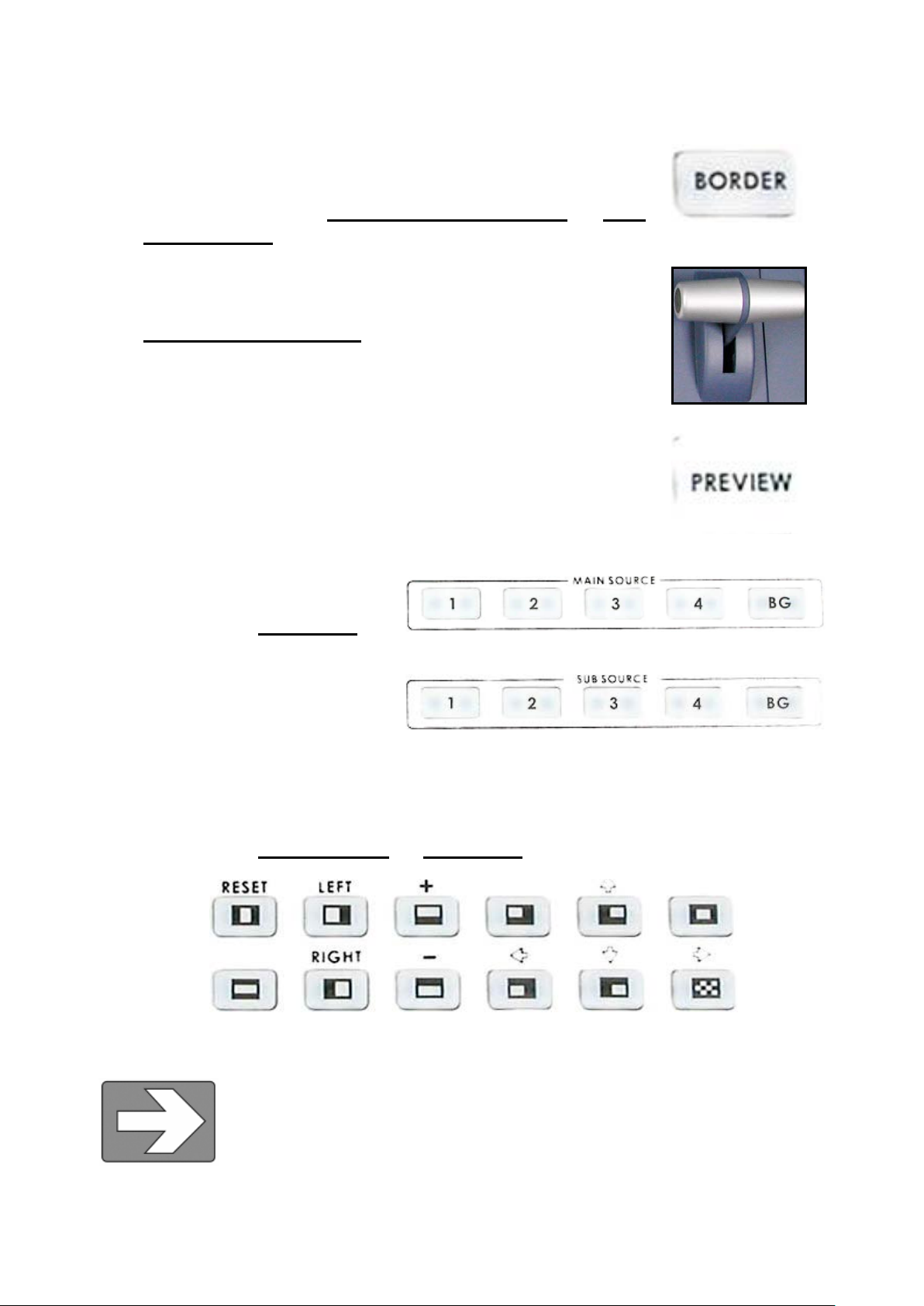
11. Border: co ntr ols the border style and color for the Pictu r e in Pic tur e ef f ec t,
and the color edge for the Wipe effect. This control is acc essible when
the Picture in Picture c ontrols, and Wipe transitions (15.) are engage d.
For more information, see Using Effects: Picture in Picture and
Transitions: Wipe.
12. T-Bar: used t o manually perf orm a transition. For m ore information, see
Playing a Transition Manually
13. Preview: pr eview the selec ted transitio n effect, and background col or by
pressing the “Preview” button.
.
Using
14. Main Video Sourc e Selecto r: Used to s elect which of the f our video input
channels or background is sent to
the Main video output. For more
information, see Vid eo Source
15. Sub Video Source Selector Used
to select which of the four video
input channels or back ground will
be transitioned to or used as a
sub source in an effect.
16. Transition sel ectors: These twelve selection buttons determine the trans ition type and allow for the
selection of certain effects that are perf ormed on the selected M ain Video Input channe l. For more
information, see Using Transitions and Using Effects
.
.
Tech note: Transcoding is the act of changing video from one format to another, for example, from
composite video to S-video. The SE-500 h as been designed to perform transcoding,
as part of its st an dard op er atin g pr ocedure. Select a video source on the Main Source
Input bus, and it will be available at the Main Output in all formats, S-Video and
Composite, simultaneously. With the exception of component (YUV) and S-video
(Y/C): only one of these output formats is available at a time.
Page 16
15
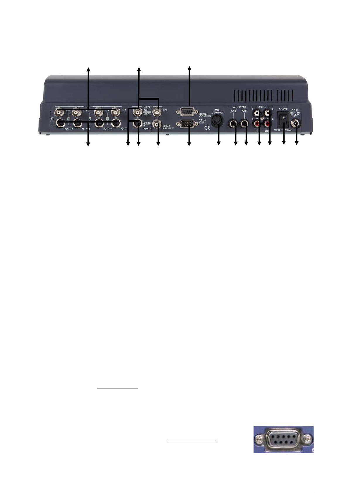
3.2 SE-500 Rear Panel
3 6 4
5
1a
1b
2a
2b
2c
2d
7 8 9
11
10
1. Video inputs, Channels 1, 2, 3, 4.
1a. S-Video (Y/C) input
1b. Composite video input (BNC)
2. Video outputs
2a. Composite video out (BNC)
2b. S-video (Y/C) out
3. RS-232 Control
4. Tally Signal out
5. MIDI Control*
6. Microphone input Ch2 (1/4” jack)
7. Microphone input Ch1 (1/4” jack)
8. Audio inputs (Stereo, RCA connector)
2c. Component (Combine Composite &
Y/C with a breakout cable)*
2d. Quad preview output (BNC)
9. Two Stereo Audio outputs (RCA)
10. Power switch
11. DC Power input 12V
1. Video In (Channels 1, 2, 3, and 4 are all set up the same way)
a. Compos ite video input: takes a BNC conn ector from the composite output of a VCR, camera,
DVD player, etc.
b. S-Video ( Y/C) input: takes a standard 4 pin S-video cable from the output of a VCR, camera,
DVD player, etc.
2. Video Output. These ports carry the Main video output of the SE-500.
a. Composite video out: BNC connector typically connected to a program monitor.
b. S-video out: s tandard 4 p in S-video (Y/C) c onnector, t ypically connec ted to a VC R, projector, or
monitor.
c. Y.U.V. video out: Combine Composite & Y/C with a breakout cable. These BNC connectors
carry the analog com ponent Main video signal, and w ould typically be connected to a master
recorder (Betacam , DVCPro, or DVCam , for example), component video monitor, or a satellite
uplink. (See Video Sources
d. Quad preview out: BNC connector carrying a quad video signal with effect, Tally light,
background, and speed indicators.
3. RS-232 control: for PC or other devices to remote control via RS-232
protocol. Please read the Appendix of RS-232 Protocol
information.
for more information on connecting these ports to a device.)
for more
Page 17

16
4. Tally Out: send out Red, Yellow, and Green colors tally signal to each
channel. Red m eans On-Air, Yellow means next camera source, Green
means free to move.
5. MIDI Control interface: for connecting to other MIDI devices, such as MIDI
keyboard, and electronic piano. Please read the Appendix of
Protocol.
6. MIC CH2: A ¼” jack connector for a high impedance analog audio source,
such as a microphone. MIC inputs 1 and 2: accept ¼” Inch mono plugs,
carrying high impedance signals from one or two mono microphones. With
high impedance MIC, the longer the cable from m icrophone to the SE-500,
the more noise is introduced into the signal.
7. MIC CH1: When a stereo ¼” jack is connected t o CH 1 o nly, the CH1 and CH2 Faders (page 11) will
have equal volum e on each channel. When both CH1 and CH2 have a MIC connecte d, each fader
channel will adjust the respective input from the rear panel.
8. Audio Inputs: A RCA stereo for a line l evel auxi liary a nalog aud io source, such
as a CD player or tape deck. If you are using more than two sources via an
external audio mixer, connect the audio mixer’s line level output to this
unbalanced Audio input.
9. Audio Output: A RCA stereo line level analog audio output, car rying the signal
present at the output of the audio mixer section (see
Operations).
10. Power: Switches the unit On / Off.
11. DC Input: connect the power supply that came with the SE-500, and only the power
supply that came with the SE-500, here, and pl ug the other end into a n electrical outlet ,
preferably on a surge suppr essor (to protect the SE-500 f rom random power spikes that
can fry its delicate insides).
MIDI Control
Controls and
Page 18

17
3.3 Selecting video input for m ats and adjusting audio levels
(Numbers refer to the Front Panel illustration above)
*. Verify that there is a valid source at each inp ut you’ve connect ed by using the Main Sour ce Select butt ons
(13.) to select a channel and view the output on the main monitor.
For each input channe l ( 1, 2, 3, 4): connect either a Composite or S-Video so urc e to e ac h c ha nne l. For more
information please see below.
Adjust any audio input l evels you will be us ing, for example m icrophones, Aux in fr om a mixer, etc. Set the
level of the LEDs in the Audio Meter s (3.) to occasionally peak at +8 or +10 and there is no audible distortion.
Tech Note: SE-500 will autom atically detect which connector is plugged. Therefore, there is no need to
change the setting when you switch the video source from S-Video to Com posite, and v ice versa. Howev er,
if you connect both S-Video and Composite inputs on the same Channel, the SE-500 will automatically select
the S-Video as main input source.
3.4 Using Video and Audio Monitors
Without reliable video and audio monitors, you won’t be able to tell what’s what in your mix.
The SE-500 provides the ability to easily and reliably monitor video and audio at the output stages.
All video input channels can be monitored on one monitor, via the Quad Preview Monitor Output, page 14.
You should have a video monitor displaying the Main Output. This could be a composite monitor, for
example, connected to the one of two CV pl ug (Compos ite) in the Vide o Output s ection (2a, page14), or to
the composite output of a VCR connected to the Video Output.
For output audio monitoring with hea dphones, set the rotary headphone volume control knob to the center.
(4.); to monitor thro ugh an amplifier and speakers, push the MASTER fader to -12 in the Au dio Faders (1.)
section. For more information, see Controls and Operati o ns
.
3.5 Cutting between sources
The simplest wa y to cut (switch) betw een source video inp uts: use the Video Main Source buttons ( 13.) to
select which input goes to the program monitor (output). Look at the results on your program or record
monitor.
3.6 Dissolving between sour c es
Select the Main Video Source (13.) by pres s ing t he a p propr ia te c ha nne l bu tton . The LED for the channel you
have selected should be lit and you should see that source on the program monitor.
Select the Sub Video Source (14.) you want to dissolve to.
The default transition is fad e (The LED sh ould be lit when you turn on the s witcher. If a differ ent transiti on is
selected at power up, pr ess it to d eselect .) Move the T-Bar (11.) to the opposite position and watch the fade
happen on the program monitor. You can stop the fade part way through and watch the Ma in source fade
away.
3.7 Other transitions between sources
Select Main and Sub sources as above.
Select the wipe you wish t o use. There are total 11 diff erent Wipe styles and the correspondin g icon will be
displayed on the preview monitor when you press it.
Page 19

18
At this point you can hit Pr eview (12.), to see the transition on the preview m onitor. Then, use the T-Bar to
perform the transition manually.
For more information, see Using Transitions
.
3.8 Effects
There are two places on th e SE-500 wher e you c an a dd eff ects : in the T ransition Eff ects section (15.) and in
the Video Effects section (5-8.). Som e of thes e work on a s ing le sour ce, and som e need t wo or f our sources
to work.
Select a Main Video source and try the following:
In the Transition Effects section, select the WIPE effect you wish to use. You could also add a border to the
edge by turning on the BORDER effect (10.).
For more information, see Using Transitions
.
In the Video Ef f ec ts s ec tion , tr y the Quad effect (5.). Press the but ton to engage the effect; t he L ED will lig ht.
You can see 4 input sources showing on the program monitor at the same time.
For Split effect (6.), s elect a sub sourc e for right ha nd side windo w. Then, pr ess the “ SPLIT” button. You will
see Main source on left hand side, and Sub source on right hand side.
PIP effect (7.), which stands for Pictur e in Picture. As you might gues s, this effect requ ires a Main and Sub
Video Source. Assum ing you have valid inputs on Ch annel 1 and 2, select Channel 1 as the Main Source
and Channel 2 as the Sub S ource. When you enga ge the effect by pres sing the PIP button ( and verifying
that the LED on the button is lit), on t he program m onitor you will have Channel 1 as the Main Source and
Channel 2 as a smaller window inset. T here are t wo choices for window size. Change these by pressing the
+ and - buttons, see below. You can position this windo w using the ot her five diff erent positio n buttons on
(15.), with the button set to Position Co ntro l (LED is lit). You could also add a border by turning on the Border
control (10.).
Next, try the Freeze effect (8.) to grab a s till frame of the Main Sour ce video. Move the T-Bar to manually
dissolve to the Sub Video Source.
For more information, see Using Effects
.
Page 20

19
4. Controls and Operations
4.1 Video Source
Selecting the Mai n and Sub Video Sources
is the first thing to do when setting up the
SE-500.
The source you s elect (by pressing one of t he buttons; a bright red L ED on the selected butto n lights for
confirmation) on the Main Source bus is what is sent to the Video output. This means that you can perform
cuts between sources by simply pressing different buttons.
The Sub Source selection determines which input will be transitioned to when using any of the transition
controls (Wipe and Fade) and provides the video for Picture in Picture and Split functions. (See
Transitions and Using Effects for more details.)
In addition to sel ecting which video input channel will be present in the Main and Sub Source busses, you
must check the appropriate input for each channel in use. (See
adjusting audio levels) The SE 500 has automatic i nput select; if there is an S-Video c able connected to
the S-Video input, the cha nnel will automatically swit ch to S-Video input. However th is means that, if both
composite and S-Vid eo inputs are c on nec te d a nd t here is no valid video signal pr es ent thru S-Video, you will
see a black video when that channel is selected for output. For ex am ple, if you have a cam corder connected
to channel 1 throu gh the com posite input, a nd you also have channel 1’s S(Y/C) connected to another nonworking device, you will see a black video, even if the camc order is supplying a s ignal. You will als o see a
black video if the camcor der is not supplying a video signal, s uch as when it is powered off, or in playback
mode with no tape loaded.
Selecting video input formats and
Tech note: The frozen image is a function of how the time base corrector (TBC, a.k.a. frame synchronizer)
works. The SE-500 has a TBC at the Main Video Source and the Sub Video So urce input on eac h channel.
Their purpose is to s tabil ize the vide o signa ls as the y com e into the s witc her, and to s ynchroni ze th eir tim ing
so that they can be switched and otherwise combined with no disruption to the video signal. For more
information on TBCs, see What is a frame synchronizer
.
Using
4.2 Color Processor
The Color Processor controls work when you press and hold the “Background” (9.)
button for 2 seconds or more, which is temporarily displa yed at t he Preview Output. For
more information, please see the “MENU
controls on a video monito r or the proc amp (proc essing amplifier) contr ols on a time
base corrector. In f act, th ey are th e proc am p c ontrols of one of the S E-500’s 4 internal
TBCs.
” section. These controls are like picture
Page 21

20
On the top of screen you can see 4 dif ferent numbers, eac h represent
1 2 3
4
Brightness
0 ±0 ±0 ±0
Contrast
0 ±0 ±0 ±0
Color
0 ±0 ±0 ±0
Tint*
0 ±0 ±0 ±0
the input channe l from the SE-500 rear p anel. On the left sid e of this
section are the 4 co ntrols ( Brig htness , Contrast, Color, and Tint (NTSC
only)). 0 stands for Unity, or perhaps Unchanged. In either case, it
shows that the signal passing through that particular control is being
neither boosted nor cut. T o move to another control, pres s the up or
down arrow button. To move to another channel, press the left or
right arrow button. To change the settings, press the
You can see the extent of color processing available in this section by experimenting with the controls.
Brightness adjusts how light or dark the colors in the image will appear at the Video Output. The Y-Gain
controls affect the range between the lightest and the darkest parts of the image, including how much
shadow and highlight detail can be seen. Col or controls the saturat ion or intensity of the co lor image, from
fully saturated or extrem ely inte nse at the top of the s cale to com pletel y de-saturated or monochrome ( black
and white) at th e bott om. The Tint buttons (NT SC only) control the actual hue or s pec if ic col or s i n t he image,
in effect rotating all the colors equally around an imaginary color wheel.
Reset works on the selected input source, and when pressed and held for 2 seconds, resets the Color
Processor controls f or just that input to 0 or unity. (Press and hold the Res et button unt il you see th e image
shake a bit and return to its unprocessed state.)
So how do you know for c ertain how effective an y of these adjustments ar e? You can see the changes b y
looking at the Main Output on a video monitor, but how do you know if that reference is accurate?
The first part of the answer is : by having an accur ately calibrated m onitor that sh ows exactl y, with reference
to a standard, what the video looks lik e. That standard has be en described and agreed to by the Soc iety of
Motion Picture and Television Engineers (SMPTE) and the European Broadcasters Union (EBU), and is
most commonly sho wn as “c olor bar s.” Col or b ars ar e an im age consisti ng of colu m ns and block s of s pecific
colors and gray ton es. Because of differences in t elevision standards, SMPTE bar s and EBU bars do not
look the same. T hey are u sed in muc h the same ways: when t hese are di splayed o n a monitor, the monitor
can then be adjusted to meet the standard.
+ or - buttons.
±
±
±
±
The most serious, accurate color correction is done with the aid of a waveform monitor/vector scope, a signal
analysis instrument (actually a pair of instrum ents) common in video editi ng suites, which shows precis ely
the details of the vid eo signal. W ith one of these instrum ents, you can see at a glance ( once you know what
you are looking for) the most intimate electronic details and irregularities of the video signal.
Many users may not have access to a waveform monitor or vector scope, but this does not necessarily
condemn them to produc e less than high qualit y video. It means that more care m ust be taken and some
different procedures must be followed.
Page 22

21
Nothing will take the place of a calibrated, pr operly adj usted monitor, so that m ust always be your first step.
For more information on monitor calibration procedure, see Appendix: Monitor Calibration
If you don’t have an y video test equ ipment, follow the suggested proce dure to adjust all th e video sources,
which is described at the end of Appendix: Monitor Calibration
Settings made in this sec ti o n ar e “r emembered” by the SE-500 after you po wer d o wn th e unit. In other words,
these settings remain in effect until they are changed or the Reset button is pressed.
.
.
4.3 MENU
The MENU works when you press and hold the “BACKGROUND” (9.) button for 2
seconds or more, which is temporarily displayed at the Preview Output. The first
adjustment is the “Color Processor” as described above. Pres s the button again, and
you can select IR E, video output f ormat, remote cont rol protocol, and color bar output.
Use the up or down arrow keys to m ove to different categories, and then use
to change the setting.
You may select YUV and CV (Composite) for video output format, and use a breakout cable to get a
Component output signal.
If you use a MIDI keyboard in live c oncerts, you will be amazed what the SE-500 can do. Go to “Remote
Control”, use
desired MIDI channel you wish to use. While you are setting th e channel on the SE-500, please also set u p
the channel on your MIDI d evice. After you finish setting, press the button again. Tur n off the unit , and then
turn it back on. Now you can start to use the MIDI device to control the SE-500. For more detailed
information on MIDI control protocol
+ or - to change the setting f rom RS-232 to MIDI . Press “BACKGROUND” again, select the
, please refer to page 48.
Tech Note: All the setting will be memorized except color bar output.
+ or -
4.4 Audio Inputs, Levels, a nd Me t er s (Faders, bus selectors,)
Audio Input Level Calibration Procedure
The first step in set ting u p the a udio f or a ses sion with your S E-500 c onsists of adj ust ing the levels o n which
channel you will be using. Push the Master fader to Max, and set the ot her f aders to 0. T hen, list ening t o the
audio and watching t he Audio Level Meters (see below), set the l evel with the fader so that the soun d is
consistently at betwee n +0 dB (green LED) and +8 dB (yellow LED) and j ust barely peaks occasionall y to
+10 dB (red LED). The ide a is to avoid an y audible distortion (cl ipping), caused b y making the signal le vel
too high at this stage.
Page 23

22
Three faders on the left represent the inpu t volumes (CH-1, CH-2, AUX), which determine what s ignals are
present at the Ma in Output. If any of the fad ers are all the way down, there will be no audi o from that input
channel heard at the output.
These faders corr espond with each input and con trol the relat ive volume of each input in the master out put
as well as the master output le vel. When the faders are set to 0, th ey pass the audio signal thr ough at the
same level it was at w hen it entered t his bus. You can increase or decrease the vo lume of each c hannel by
moving the fader up or down.
These meters sho w the au dio signal level at t he Main output. T he strengt h of any a udio signa l that is route d
to the output will be displ ayed here. As mentioned ab ove, these meters pla y a vital part in correctly setting
the audio levels t o avoid c lipping or other distortion . You’ll notice tha t the LEDs a re green u p throu gh the + 0
dB level, turn yellow at +4 dB, and tur n red at +10 dB. As you set t he audio level for eac h input, m ake sure
that the signal peaks to +8 dB or very occas iona lly to +10 dB. Every time the signal go es to +12 d B, it w ill b e
distorted.
Use the Headphone section to accurately monitor with the “Master” volume
output. In many cases, headph ones may be a m ore useful and accurate c hoice
than speakers f or audio monitoring. For example, in a noisy club or at a concert,
you won’t be able to hear any additional sound coming through speakers.
Headphones will als o more accuratel y reproduce the sound you wish to monitor
at a lower cost than speakers.
Page 24

23
5. Using Transitions
The SE-500 can do 3 k inds of transitions: cut, fade, and wipe. The cut is a simple switch fr om one input
source to another, and can be accomplished by selecting a source on the Main Source Bus, and then
selecting a second one. One source is replaced by the next at the video output. Not flashy, not fancy,
nothing to customize, but gets the job done. In fact, if you watch a film or video, paying attention to
transitions, you’ll see that the cut is far and away the most often used transition.
When you want a transition that is more stylish or fancy, see the next section.
5.1 Selecting a transition: Fade, Wipe
First, some definitions:
A fade, also known as a dissolve, is a trans ition wherein all the pixels of one so urce are replaced by all the
pixels of another, at a smooth rate, and at the same time.
In a wipe transition, the ch ange from one sourc e to another happens alon g a predefined edge. It is like one
source is being pulled back or pushed on to the other.
But a picture is worth a thousand words, so...
Select a main source and sub source, select W ipe, or Fade from the buttons ab ove, press “Preview” button
to see what it would like on progr am. Then, perform the actual transition manually by movin g the T-bar up
and down. See below for a list of transitions and variations.
5.2 Playing a transition manually
The T-Bar is the tr adit ional switc her de vice for per form ing trans itions m anuall y; it c an
be either all the way up, all the way down, or anywhere in between. The up a nd do wn
positions are relative, meaning one position is before and one position is after the
transition.
The T-Bar perform s the selected transition bet ween the selected sourc es as fast as
you move the T-Bar. And it performs as much of the transition as you want.
If no transition is selected, moving the T-Bar performs a fade between the selected sources.
5.3 Playing a transition automatically
The auto transition can be performed by RS-232 or MIDI control. In the aut o-take, there are thre e different
speeds you could select. For further detail see RS-232 Remote Control Command and
Control Command.
MIDI Remote
Page 25

24
5.4 List of transitions and para m e t er s (suitable for photocopying)
Wipe (works in conjunction with Border controls):
1:
2:
3:
4:
5:
Block wipe from center to full screen.
Right angle wipe on, upper right to lower left
Right angle reveal, lower right to upper left
Right angle wipe on, upper left to lower right
Right angle reveal, lower left to upper right
6:
7:
8:
9:
Horizontal wipe, top to bottom
Horizontal wipe, bottom to top
Vertical wipe, left to right
Vertical wipe, right to left
Page 26

25
10: Vertical wipe, middle to left and right
11:
Horizontal wipe, middle to top and bottom
Page 27

26
6. Using Effects
The SE-500 is capable of producing a wide variet y of digital effects. These falls into 2 categories: single
channel and dual channel effects.
Single channel effects are produced on the source selected in the Main Video Source bus and need no
second video input. Single channe l eff ects include Freeze.
For example, select any input channel having a valid signal as the Main Video Input. Press the Freeze button
once. You’ll see, on the pr ogram monitor, that the s ource video stops ins tantly. Press the butt on again, and
watch the source video retur n to full motion. With the Free ze effect, there are no parameter s, just a single
source stopping and starting.
For more information on single channel effects, see the appropriate section (Freeze) below.
Dual channel effects are produced on the source selected in the Main Video Source bus and require a
second source, whic h is alwa ys selected in the Sub V ideo Source bus. Dual c hannel eff ects include P icture
in Picture.
For example, select Main and Sub Video Sources, and then press the PIP (Picture in Picture) button;
immediately, on the program monitor, you will see the Sub Video Source in a small window.
For more information on these dual channel ef fects, see the appropriate s ec ti ons (Quad, Split, and Picture in
Picture) below.
6.1 Effects: Quad
The Quad effect c ombines 4 input videos into 1 output. W hen this effect is activated, it
shows 4 video sourc es on 1 single monitor. Each s ource takes one quarter of the entire
screen. Press the button again, and it returns to the previous selected source in full screen.
This is a dual channel effect, and cannot be used with any other transitions or effects.
6.2 Effects: Split
This effect will squeeze the Main Video Source and Sub Video Source into a half size
screen. The default se tting is Ma in Video Source on t he left , and th e Sub Video S ourc e on
the right. Select diff erent sources for the left window by pressing diff erent channels on the
Main Video Source. You could switch from left to right, or ri ght to left by pressing the “LEFT” or “RIGHT”
Page 28

27
button. You could a lso s e le ct different sources for the left wind o w by pressing 1-4 channel on M ai n sour c e or
pressing 1-4 channel on Sub source for right window.
6.3 Effects: Picture in Picture
The Picture in Picture effect puts the selec ted Sub V ideo Sourc e in a windo w on the M ain
Video Source. Variables f or this effect include window size and positi on. Eng ag e t he ef f ect
by pressing the Picture in Picture button and verifying that the LED on the button is lit.
Window size (2 si zes are ava ilable); c hange the windo w si ze by pr essing the
the Wipe transitions. (
There are 9 differ ent positions that are located on the right of the Wipe transition eff ects. Select from one of
the preset locations b y using the buttons. O n each corner, use “Right” and “Left” to move the windo w closer
to the edge or to the center.
This effect may also be used in conjunction with the Border keys (see below).
This is a dual channel effect, and cannot be used with any other transitions or effects.
+ is larger, - is smaller).
+ and - buttons on the left of
6.4 Effects: Freeze
This effect freezes the incom ing video, as sel ected on the Main Video Source Bus. There
are no parameter s, no variations. Press the butt on once and the video free zes, press it
again, and it returns to the selected source in full motion.
The Freeze effect is single channel, and can work in conjunction with any transition.
6.5 Border
These controls are us ed in conjunction with the Picture in Picture Ef fect and Wipe transition
only, and can only be activated when the Picture in Picture or Wipe control is active.
8 Colors are available for the border: black, blue, magenta, red, green, cyan, yellow and white. See
“Background Color” below. (Wipe only. In PIP mode, the border is set to white color only.)
6.6 Background
While not strictl y an effect, these controls are in the same general ar ea, and we thought
you’d look here for any inform ation you might n eed. These c ontrols selec t what solid c olor
the background will be w he n selec te d on e ith er the M a in or S ub V id eo bus . T her e ar e eight
possible background colors; see below, with the identical LED lights displayed and the indicator on the
preview monitor output. The background colors are: black, blue, magenta, red, green, cyan, yellow, and
white.
Engage this control by pressing the button in this section. The LED’s color will correspond with the
background color (except black) to indicate that the controls are active. Repeated presses of the button
select different colors.
Page 29

28
7. Sample applicati ons
We figured, being practical minded, that the best way to show off what t he SE-500 can do is to give you
some examples of how it c ould be use d in rea l life s ituations . Each exam ple r efers to a block diagram for s et
up and connections.
Each of these examples is meant to illustrat e a typical type of use for the SE-500. Needless to say, there will
be many variations on an y of these themes. T ry to look for the principles of each set up and adapt thes e to
your particular situation. As you get deeper into work ing with your SE-500 in dif ferent situatio ns, you should
familiarize yourself with the Tech Notes, Accessories sections, and Appendix
do various things with your digital Switcher.
for a quick index of how to
7.1 Four Camera Shoot: Live Stage Perf ormance / Sporting Event
The first example is a t ypical four-camera shoot. T he example is based on a stage perf ormance such as a
play or a band, b ut it c ou ld j us t as e as ily be slightly modified for oth er live s itu ati on s s uc h as sp or ti ng ev ents .
The four cameras are feeding analogue signals to the SE 500, via Composite or S-Video. It would be
possible to use DV cameras by adding a Datavideo DAC 6 to each of the channels that you want to run DV.
With four cameras it may be worth using the Tally Light feed, so t hat the camera operators will be a ware
when they are live, or save to re-position.
Depending on the c omplexity of t he shoot, you m ay want to use an external Mic/Aud io Mixer to handle the
audio and then chan nel the output of the a udio mixer to the S E 500, or simpl y use the two Mic inputs a nd
have an audio source, s uch as a CD player for background m usic. If you shoot a sporting even t the main
microphone would be the commentator and the second Mic would be crowd noise.
The output can be recorde d li ve to tape or DVD, or alternatively it could be s ent t o a gi ant s cr een or pr oj ec to r.
The vision mixer operator will be responsible for ensuring the right camera feed is selected and that
switching from camera to camera is carried out at appropriate times.
Page 30

29
7.2 Live Conference
In this second example we see a typical conference set up.
There are two camer as to handle the speaker and the ov erview, with audience reac tion or other action on
the stage. Both cam eras are ana logue, but b y adding a DAC 6 t o an y of the chan nels it would b e possi ble to
use a DV camera.
There is a VCR or D VD player cued up with f ootage t o enh ance the speaker’s presentation, and a feed f rom
a laptop of a PowerPoint presentation that the speaker will be referencing throughout his speech.
There is a microphone feed from centre stage, and the pos sib il ity of a second microphone for ambient sound
or perhaps to field questions from the audience.
The output can be fed to a giant screen, video-wall or projector; the audio output can be fed to the P.A.
System.
In this situation the v ision mixer operator will take cues from the speaker for when to introduce the video
footage and PowerPoint presentation. The operator will also control the volume levels of the two
microphones and the audio feed from the VCR / DVD.
Page 31

30
7.3 Live Event Mixing: Club VJ / Conce rt
In our final exam ple we are looking at a typical V.J. set up. Increasingl y in clubs video images are used to
add to the overall effect and atmosphere, they are combined with light displays and other audio / visual
effects.
In the set up above we see two cameras being used , one on the audience and the s econd on the V.J, it
could just as easily be a second angle of the audience.
There are two DVD or VCR sources, these could be showing animated patterns or backgrounds, promotional
videos, music vide os, just about anything. T he audio from one of the DVD decks is being f ed into the aux
audio input; although it is m ore likely you would run both the DVD pl ayer audio feeds int o an extern al audio
mixer, together with CD pl ayers, keyboards and other audio f eeds. The mixed output from the audio m ixer
would then be fed into the SE 500.
The job of the V.J is to control everything that is seen and heard. Combining video and audio images
together in an entertaining way. It is possible the V.J may control the SE 500 via MIDI control from a
Keyboard, or sequences the whole show via RS 232 and run it all from a PC.
Page 32

31
7.4 Using SE-500 with CG-100 for Titles/Graphics/Logos overla y
Using YUV output (with a breakout cable) on SE-500 to communicate with a PC with Decklink SP CG
overlay card and CG-100 CG software
to perform a text overlay for the output video.
Page 33

32
8. Troubleshooting
No power
No image at output
Audio clipping
Audio or video feedback
Frozen image at output
Image distortions
8.1 No power
1. Check that t he po wer s u pply is plugged into the SE 50 0, a nd to a s uit abl e mains outlet, and that it
is switched on.
2. Move the SE-500 to a cooler location and allow the unit time to cool off before powering on again.
8.2 No image at output
3. Incorrect video input format selection
4. Check that the output format is set correctly for S (Y/C) or Component.
8.3 Audio clipping
1. Audio input level is too high.
2. Incorrect calibration of audio input level.
8.4 Frozen image at output
3. The Freeze function was activated
4. The video input source is no longer valid, or playback has stopped.
8.5 Image distortion
1. The video input level is too high
2. The video quality is poor from video input source.
Page 34

33
9. Appendix
Glossary of Terms
Analog video: a video signal that is recorded and played back using changes in magnetic levels recorded
on a tape or disk, e.g., the video we see when we watch a VHS videocassette.
Animation: a video or film sequence that gives the illusion of motion by presenting a series of images or
photographs.
Balanced audio: a 3 wire circuit for audio, with the 2 legs of the circuit balanced with respect to ground,
usually terminating in a 1/4” phone or XLR connector, having excellent noise rejection capability.
bit: the smallest unit of computer memory.
Black burst: video signal used to synchronize the scan timing of multiple devices.
BNC: a connector with a secure locking feature, used for video signals.
Brightness: the darkness or lightness of an image or color; see also, luminance
CD: compact disc, an optical recording system popular for audio and data.
CD-ROM: a subset of CD standards (ROM stands for “read only memory”); holds about 700 MB of data.
Chroma: the color component of a video signal.
Chroma key: a color-based video matte (overlay) system that drops all areas of a selected color, of ten gr een
or blue, from one image and replaces them with the corresponding areas of a second image.
Component video: video system where the color and luma components of the video signal are kept
separate (as Y.U.V. or RGB, etc) to maintain highest image quality.
Composite: 1) the combination of several images into one; 2) video system where the color (chroma) and
brightness (luma) signals are combined into one waveform.
Compression: translating data into a more compact form by discarding redundant information, then
reconstructing the data to its original form; can be either lossless or lossy.
Color correction: the use of filters, processing amplifiers, and other software and/or hardware devices to
correct a video image
dB: a unit of measurement for audio signal levels.
Digital video: a method of representing still or moving images by number values instead of by varying
magnetic levels (analog video).
Dub: a copy.
DV: a digital video format recorded at 25 Mbps using (roughly) 5:1 compression.
DVCAM: Sony’s version of native DV format in a professional sized tape format.
EBU: European Broadcasters Union, the professional standard setting organization for European television.
Field: for a video signal, a set of lines produced by one sweep down the screen. For interlaced video (what
we watch on TV), it takes two such fields to make one frame (complete image).
Filter: 1) A partially transparent material that passes or blocks certain light colors;
2) An electronic circuit or unit that passes or blocks signals of a particular type or frequency;
3) Any circuit or device (hardware or software) that shapes or conditions a signal or information.
FireWire: Apple Computer’s trademarked name for IEEE1394.
Frame: 1) to compose a shot in video or film, to make the image fit into the “frame” of the screen;
2) a complete video image.
Frame synchronizer: a digital buffer that stores a frame of video, compares the sync information to a
reference, and releases the frame at a specific time to adjust for timing errors.
Glossary: a list of difficult or specialized words for reference.
GPI: General Purpose Interface, a simple trigger device.
Hue: a specific color; one of the 3 attributes of color, see also saturation, brightness.
IEEE1394: a low cost digital interface that can transport data at up to 400 Mbps.
Page 35

34
Impedance: A.C. resistance in an electrical circuit, measured in Ohms. Impedances must be matched in
audio circuits to avoid distortion and the introduction of noise.
Key: 1) in lighting, short for key light, the principle (usually brightest) light used to illuminate the main
subject;
2) to switch between two or more video sources using a control signal;
3) an image whose color or brightness is used to determine the switching between two or more video
signals.
Level: another word for signal strength, power, volume.
Line level: an audio signal level, between –10dBu and +30dBu, likely to be the output of a cassette deck or
CD player as opposed to that of a microphone. Line level signals are most often unbalanced
Luminance: the brightness or intensity of an image, in particular the brightness without regard to color.
Microphone level: a high sensitivity audio input intended for low level signals, such as a microphone,
typically below –30dBu.
Non-linear editing (NLE): video editing methods that record source clips on a hard disk, allowing the user to
assemble the clips into any order and see the result without shuttling through the tape from
beginning to end.
Overdub: to add a signal or channel to existing material, espec ia ll y audio.
Overlay: to show one image (still, moving, or text) on top of another image.
Pan: moving the camera or point of view horizontally. See also tilt, zoom.
Parameter: a limit, boundary, or defining term.
Pixel: picture element, the smallest part of a picture that can be addressed or changed in a digital image.
Posterize: to transform an image to a more stark form by rounding all tonal values to a smaller number of
possible values, with the result bein g visi ble band ing.
Resolution: a measure of the detail in an image or a sound. Image resolution is often described in pixels
(i.e., 1024 x 768 pixels) or bit depth (i.e., 8 or 10 bit). Sound resolution is described in terms of
sampling frequency (kHz.) and bit depth. The higher the numbers, the greater the possible detail.
RGB: one format of component video; one of the descriptions of component color space, in this case Red,
Green, Blue. See also Y.U.V.
Sampling frequency: the number of times per second that a sound's waveform is captured and converted to
digital form, expressed as kiloHertz (kHz.).
Saturation: indicates the strength or richness of a color; from paint mixing terminology, the amount of the
color pigment in the mix.
SDI: Serial Digital Interface, a standard for 10 bit digital video with a transfer rate of up to 270 Mbps.
Shot: a single continuous run of film or videotape.
Signal: an electrical current that transmits video or audio inf ormation.
SMPTE: the Society of Motion Picture and Television Engineers, the standard-setting professional
organization for American television.
Solarize: to invert a range of brightness values in an image.
S-video: Y/C separated video, used with a specific round, 4 pin plug.
Sync: electronic pulses that synchronize the scan rates of different components (cameras, recorders,
switcher, etc.) in a video system.
THD (Total Harmonic Distortion): Of a signal (most often audio), the ratio of the sum of the powers of all
harmonic frequencies above the fundamental to the power of the fundamental, usually expressed in
dB. Useful measurement of the accuracy of an amplifier or signal processor.
Tilt: camera movement of pointing the lens up or down
Time Base Corrector (TBC): a frame synchronizer used to correct timing errors in a video stream.
Unbalanced: an audio circuit in which the 2 legs are not balanced with respect to ground. Less expensive to
make, but more susceptible to noise and distortion.
Page 36

35
Vector scope: a test instrument for displaying color hue and saturation in a video signal used to aid in color
correction.
Waveform monitor: a test instrument which shows a graphical representation of the luminance levels of the
video waveform, used, in conjunc ti on with a vector sc o pe, as an aid in color and i mage correction
and video system set up.
White balance: the adjustments of color circuitry in a video camera to produce an image with balanced white
and color components, where the white component has a specific color temperature or color cast.
Y/C: the separate processing of the light (luma or Y) and chroma (C) parts of a video signal for higher image
quality than composite video; a.k.a. S-video.
Y.U.V.: one of the formats of component video; one of the descriptions of component color space, in this
case Y (luminance), and U (blue), and V (red) hue saturation.
Zoom: 1) to change the size of an area selected for display to provide either a more detailed view or more
of an overview;
2) for a camera shot, to change the distance relationship between the camera and subject.
Page 37

36
Tech Notes
Books are written about m any of th e topics belo w, larg e and c om plex book s. Look for them if you want m ore
information than what we have pr esented here. What we want to do here is to prov ide a bit more in depth
information, deeper background, on some relevant topics, and give you a framework for further technical
investigations.
Video Standards, Formats, and Quality
Video standards refer to the broadcast and/or viewing systems; they are specific to certain regions of
the world. In the US, Canada, and Japan, t he a nal og s tandar d is N T SC ( which s t ands f or Natio na l Television
Standards Comm ittee, the organ izati on that form alize d the s tandard) . In Euro pe (ex cept Fr ance and E aster n
Europe), the standard is PAL (“phase alternate line”). In France, the Middle East, and most of Eastern
Europe, SECAM (“sequential coleur avec mémoire”) is the standard.
Why is this important? In part, because each standard requires compatible monitors, cameras, VCRs,
projectors, and switchers. The signals are electronically different from format to format, and so cannot
interoperate unless the equipment is specifically designed to be multi-standard.
Within each standard are m ultiple formats - different systems of recording video onto diff erent types
of medium.
At the lowest quality and c ost level is VHS, a com posite form of video, m eaning the chroma (color)
and luma (lightness) bits of information are electronically mashed together into one signal: convenient,
inexpensive, and very much of a compromise of image quality. Colors are not reproduced especially
brilliantly, but first’s generation quality is usuall y high enoug h for ac curate vie wing. 8mm is the similar f ormat
but recorded on narrower tape. Plugs for composite video can be either RCA or BNC.
Y/C, or S-video, is so named because the chrom a (C) and luma ( Y) information is k ept separate in
the signal, processed s eparatel y, and ev en transm itte d separate l y. The res ult of this s eparat ion is f ar greater
color fidelity and detail. S-video can be recorded onto specially formulated VHS (S-VHS) or 8mm (Hi8) tapes.
There is a special 4 pin connector for Y/C signals.
There are many variations of 3 wire analog component video: Betacam, MII, etc. They are all
relatively (but not c ompletely) similar ways of descr ib in g a co lor space like Y/C, except that t he C c omponent
is broken into 2 signals, for maximum color reproduction, fidelity, and detail. You may see the signal
described as RGB, YUV, YCC, Y B-Y R-Y. Usually cables with BNC connectors are used for c omponent
signals.
The point of all this technical information is u ltimately to help you to make high qual ity video: video
that looks good and serves the purpose for which it is made. But how do we know if the video is of high
quality? And what does that really mean?
There are certain technical standards that video must meet simply in order to be viewable on a
monitor. And beyond that f airl y cut and dri ed rea lm is the area of aesthet ics. W hich lea ves us with the notion
that most discussions of video quality are relative, in the sens e that there is a context, a purpose to which
definitions of qualit y level relat e. For ex am ple, a video that look s acceptable on an inex pensi ve tel evisio n set
might look absolutel y hor rible on a high end video monitor. Is this bec ause the expensive monitor cannot
display the video properl y? No, probably not. In fact, the reverse is true: the inexpensive monitor doesn’t
show enough of the s ignal to reveal ho w bad it actua lly is or where the problem s actually lie. The c ontext in
this case is the display, the quality of the monitor.
As video makers, we have to produce to the quality specifications our clients’ demand, what is
appropriate for the pr oject, what t hey can aff ord. If the c lients are ours elves, then the quality l evel has to b e
better than the weak est link in the viewing cha in - now or in the future - but not so good t hat the cost of
producing prohibits the produc tio n.
Page 38

37
One important wa y, perhaps the most im portant way, to mak e sure that your video really looks as
good on other monitor s as it does on your s is to monitor the v ideo with a properl y calibrated monitor of as
professional-level qu ality as you can af ford. See below f or some methods to calibrate monitor s. And it goes
without saying that you should have dependable, high quality audio monitoring as well, either through
headphones or speakers you can trust.
A second way to be sure that your video looks as good as it can is to use, if available, monitoring
test equipment (waveform monitor, vector scope) in parallel with the well-calibrated monitor mentioned above.
Monitor Calibration (procedures, test patterns/bars)
The following techn ique was suggested by an old broadcast engineer who beg an working in video
when tape was two inch es wide and scene changes were made with r azor blades and tapes; Fades and
dissolves did not ex ist. One had to walk up 6 f lights of stairs to the studio and back, often carrying a 65pound camera. Test instruments were expensive and often unavailable. Network engineers had to find a
convenient, simple, reliable way to calibrate monitors that could be done in the field. (You could always
recognize one of these fello ws by the Wratten 47B (d ark blue) t hey kept in their wallets or in their mechanical
pencil pocket protectors, along with their little screwdrivers.)
To calibrate a monitor is to adjus t it so that it d isplays colors th at are the sam e as a standard. T hat
standard, and a major aid t o calibration, is called c olor bars: a pattern of c olored strips (and in some c ases
gray scale strips) of very specific colors, arranged in a very specific way.
To do the following calibr ation procedure, you will nee d a source of standard col or bars. There are
several possible places to get this: your c amera may generate bars; perh aps your black burst generator pu ts
ouT-Bars; you could use a graphics program on your computer to display an image of standard color bars.
There are numer ous places on the I nternet to download s tandard color bars if you don’t have them; do an
Internet search for “color bars” and take your pick.
The following proced ur e wil l b e d es cr ibed usin g SM PTE bars, but EBU bars will wor k f or m os t of this
technique as well. As you will see, they bars are different in f ormat, in part because of the diff erences in
broadcast systems between NTSC and PAL, but much of the usage will be the same. You can use the
SMPTE bars regard less of w here you ar e an d what vi deo s ystem you are produc ing f or, jus t as you can us e
EBU bars wherever. You’ll notice that the EBU bars don’t have the gray scale information
The first thing to do is to ge t the co lor bar s displ ayed on the m onitor you want to c alibrat e. An d then,
locate the image controls on the video monitor, as these are the ones we will be adjusting.
Turn the contrast control to its midpoint. Turn the chroma (color) control all the way down so the
screen image is shades of black, white, and gray.
Look in the lower right cor ner of the color bars . In the absolute low er right corner is a black square.
Immediately to the left of that black square are three thinner vertical bars. (These are called Pluge Bars,
which stands for Picture Li n eup G en er at ing Equ ipment.) Actually, when the monitor is cor r ectl y adjusted, you
should only see two of these bars. Adjust the brightness contr ol u nti l th e b ar on the right is just barely visi ble,
and the bar in the middle is just not visible.
Now look at the lower left hand corner: the second box in from the left is a pure white. Turn the
contrast control all the way to maximum and watch the white box flare and bloom. Now turn down the
contrast control j ust until t he white box begins to c hange noticeab ly. At this point, the Plu ge Bars sh ould st ill
look as you set them in the previous step above: on l y t he ri ght most should be barel y visible. If that is n ot the
case, adjust the brightness contr ol unt il it is.
If your mo nitor doesn’t have a blue onl y switch, you have to do this next bit s trictly by eyeball and
luck: put the color contr ol to t he midpoint, and adjust the hue control so that the vertical yellow bar is a lemon
yellow (no orange or green tint) and the vertical magenta bar should not tilt toward red or purple.
If your monitor does have a blue only s witch, or if you can f ind some blue lig hting gel (like Wr atten
47B dark blue), mak e it so the monitor is b lue only. As you look at the top half of the bars , the large vertical
Page 39

38
bars should look like altern ating bars of equal brigh tness. Adj ust the chrom a control until t he gra y bar on the
far left and the b lue bar on the far right are of eq ual intensity. As an aid in doing t his, look at the line of
horizontal bars and m atch the gra y vertical bar on t he left with the gr ay hori zontal bar on th e right. Or do the
same with the blue bars.
Next adjust the hue control until the cyan and magenta vertical bars are of the same brightness. Use
the same technique d esc ribed abo ve, m at ching the vert ical bar with t he d iagon ally op posite h ori zontal bar o f
the same color.
The goal of these last 2 ad justments, to chrom a and hue, is t o mak e the 4 large vertical bars (gray,
cyan, magenta, and blue) of all the same intensity or brightness.
When that is done, turn off the blue onl y switch or rem ove the blue filter, and look at some program
material (video) w ith skin tones, and use that as a somewhat subj ective (though accurate) basis f or making
fine tuning adjustments to chroma and hue.
If you have a wavef orm m onitor and/or a vect or scope, you can and probabl y do use it to chec k and
adjust the input video sign als. The instruction manual will give you all the informat ion you need. But, if you
don’t have a waveform monitor/vector scop e to adjust incom ing video, you can m ake those adjustments by
eye, using the SE-50 0’s co lor proces sing c ontro ls, no w that you have a pr oper ly c alibrate d progr am monitor .
The process for eac h input channel will be ver y similar to th e process we j ust used t o calibrate the pr ogram
monitor, except we were adjusting the controls on the m onitor, and no w we will be a djusting the c ontrols on
the SE-500. For each input you plan to b e usi ng, ha ve a val id signa l and a djus t the Co lor Proc essor contr ols
on the SE-500 in this order:
1. Set Y-Gain to Zero; turn color all the way down so that the image is gray;
2. Adjust brightness until the image shows shadow detail and no blown out highlights;
3. Adjust Y-Gain until just before the highlights bloom;
4. (NTSC onl y) Bring the color control back to its midpoint; adjust hue s o that the skin tones l ook
natural;
5. Adjust color, an d hu e if nec es sary, to keep the skin tones natural and not oversatu r ated ( too red) .
Page 40

39
Specifications
Video Formats
Analog Y/C, Composite CCIR601 NTSC and PAL (PAL and NTSC are separate models)
Video Inputs
4 – S (Y/C), Composite
Video Output
1 – Quad Video source monitoring (Composite)
2 – Composite
1 – S (Y/C)
1 – Component (With breakout cable, it uses the S (Y/C), and one Composite output.)
Audio Inputs
1 – Stereo input (RCA connector)
2 – Mono Microphone (1/4” phono jack)
Audio Output
1 – Stereo main outputs (RCA connector)
1 – Stereo headphone (Mini jack with volume control) 0.3Wrms 8 ohm
Quad Channel Time Base Correction
Full Frame Synchronization, 4:2:2, 13.5MHz
Digital Effects including
A/B dissolves, PIP, border lines, and ov er 12 Wipes with various manually transition speeds
RS-232 Data Control Port
Connecting PC RS-232 for remote control
Color Processing
Brightness +/-10%
Y-gain +/- 3dB
Color +3/-10dB
Tint +/- 10 degrees (NTSC only)
Video Bandwidth
Component 5.2 MHz
S (Y/C) 5.0 MHz
Composite 4.5 MHz
DG, DP +/- 3%, 3 degrees
Signal/Noise Ratio:
Video > 50 dB
Audio > 65 dB
Page 41

40
Audio
20 to 20 KHz +/-3dB
Audio THD <0.1%
Dimensions W x D x H
15.75" x 10.5" x 3.25" (Approx)
400mm x 265mm x 83mm (Approx)
Weight
5.5 lb, 2.2 Kg
Power
Input: DC 12V, 1.5A (11W)
Page 42

41
Useful Accessories from Datavideo
Datavideo CG-100
THE FIRST AFFORDABLE SDI CG SOLUTION LIVE SDI TITLE / GRAPHIC / LOGO OVERLAY
CG-100 can be used in any SDI or YUV input switchers. It can be also used in SE-500 via YUV output
interfaces.
SDI overlay off ers the best, broadcast q uality, CG so lution
in the industry toda y. However, i t has al ways been be yond
the budget of sm all studios and production houses - The
Datavideo CG-100 has changed that!
The CG-100 combines with a Blackm agic Design Deck link
Card to bring you live SDI CG overlay at an affordable
price. It supports NT SC and PAL video standards and is
able to generate graphics for 16:9 or 4:3 aspect ratios.
Pages can be composed and combined with animation
effects, to run as a sequence, or they can be displayed
and edited live. The CG-100 combines perfectly with the
SE-500/SE-800 to give superb quality graphics / text / logo overlay on live production mixes.
Datavideo VGA to DV converter- PPT-100
In many conferences and seminars, lecturers need to
present videos and additional PC information to the
audience. When the y switch sources between PC and other
medias on the projector, will cause the transient black
picture and then interrupt the meeting proces s. The solution
is a high-end VGA to video con verter, which converts VGA
to high-resolution video, enabling the PC output to be
selected via a video switcher.
Thanks to Blackm agic Design and Datavideo the solution is
at hand. Blackmagic Design have introduced a low cost
range of SDI solutions, which are called the “Decklink
Series”, and Datavideo have developed the f irst software for
displaying VGA direc tly out thru these Dec klink SDI cards. The Datavideo PPT-100 takes full advanta ge of
Page 43

42
the Decklink card and Intel 915 chipset technology. Users can easily convert PC images (VGA) to SDI,
change image position and size, and select diff erent colors for the pointer; and then, d isplay on projector or
large TV wall. With a vision mixer / switcher such as the SE-800, you can also combine DVD player, DV
camera, VCR, VHS and CD player for a perfect presentation.
Datavideo TLM-70D 7” TFT LCD
Datavideo TLM-70D is a 7” TFT LCD monitors, 3U height design w ith T LM-70JF you can easily to insert it on
standard 19" rack cabinet. NTSC/PAL video format
auto recognition (Ana log video only) with vide o passes
through 75-ohm self-terminated video output
connector. The "AUX" input provides options for
external form at conver t ers s uc h as SDI input converter.
With contrast, brightness, color and tint (Tint only
available for NTSC) controls for a best view quality of
display.
LCD Display 7" TFT LCD active matrix, resolution 1480 x 234
Aspect Ratio 4:3/16:9
Brightness (luminance) 250 NITs
Video Input 1.0 Vp-p, 75 Ohm
Video Output Loop-through with self 75 Ohm-terminated
Video System NTSC/PAL auto recognition (Analog only)
Tally Indication 3-color Tally LED indicators
Power Consumption DC12Volt. 50W.
Datavideo DAC-6 DV to Analog (One way converter)
The DAC-6 is designed to allow DV cameras to be
used with the SE 500. It is a stand-alone converter that
takes a DV signal in and converts it to an analog
output, in Composite, S (Y/C) or Component f ormat. It
is a very compact converte r and can be run fr om a 12
Volt battery in the field, or via the power adaptor
supplied.
Page 44

43
Datavideo BAC-03 Balanced-Unbalanced Audio converter
One channel DV repeater (VP-314)
One input to five channels output DV-DA (VP-332)
20/10 meter DV
P/N: 2066/1066
The BAC-03 is a bi-directional unbalanced to balanced and balanced to unbalanced audio convert er, with
four independent amplifiers providing stereo audio input and output.
SPECIFICATIONS UNBAL to BAL output BAL to UNBAL output
INPUT LEVEL -10dBv nominal 0dBm to +8dBm nominal
INPUT IMPED 50K ohms 0K ohm
GAIN +4 to +20dB -20dB to +18dB
OUTPUT LEVEL 0 to +8dBm nom, +22dBm max -10dBv nom, +20dBv max
OUTPUT LOAD 600 ohms or higher, balanced 600 ohms or higher, unbalanced
FREQ RESPONSE 20Hz to 25kHz, +/-0.5dB 20Hz to 25kHz, +/-0.5dB
NOISE LEVEL 80dB below nom output level 80dB below nom output level
DISTORTION <0.01% at any frequency <0.01% at any frequency
POWER INPUT DC 12V, 500mA
DIMENSION 140(W) x 112(D) x 40(H) mm
Bi-Directional IEEE/1394 DV Format Repeater
Allows extended D V cable runs. If you want to run
a DV cable more than 20 meters an in-line bo oster
is required, the DV repeater is just that. Use one
every 20 meters for cable runs of up to 200 meters
Please check website (www.datavideo.com
accessories for the SE-800.
) for the most up to date list, descriptions, and pricing of
cable
Page 45

44
SE500 RS-232 Remote Co ntrol Command
1st
2nd
3rd
4th
5th
6th
7th
,,,
Last-2
Last-1
Last
Header
ID
Length
Data0
Data1
Data2
Data3
,,,
Chksum_L
Chksum_H
End
4th
5th
6th
7th
8th
9th
10th
11th
…
Command
Group
Operated
#0
Operated
#1
Operated
#2
Operated
#3
Operated
#4
Operated
#5
Operated
#6
…
VER: 1.03
Release date: 200 6/02/22
1. Physical layer
1.1 Control output format: RS-232C
1.2 Communication rate: 57600 BPS
1.3 Data format: 8 bits serial, LSB first, 1 start bit, 1 stop bit, odd parity
1.4 Must delay 100uSEC between 2 bytes
2. Data link layer
2.1 Frame format
1) Header
Code consisting of one byte for frame synchronization.
The frame header send from the master machine is termed the command header.
The frame header send from the slave machine is termed the return header.
The command header byte is fixed as fallow.
1st: F0h (base 16)
The return header byte is fixed as fallow.
1st: FCh (base 16)
2) ID number
The equipment ID number is composed of 8 bits
The ID of SE500: 32h (base 16)
3) Length
The length is the sum of bytes from the header to the end.
It is composed of 8 bits.
6h (base 16) < Length <= 80h (base 16)
4) Data
Data block used by application layer.
Refer to Section 3.
5) Checksum
The 8 bits checksum is obtain from header to the last data, and then convert to two numeric
ASCII code.
Checksum=header+ID+legth+data0+data1+…+data_last
chksum_L=(low nibble of checksum) + 30h
chksum_H=(high nibble of checksum) + 30h
6) End
The end byte are fixed to FFh(base 16).
3. Application layer
The application layer designates the command structure and contents.
3.1 Command data format
Page 46

45
1) The command group
4th
5th
6th
7th
8th
9th
10th
11th
…
Command
Status
parameter
#0
parameter
#1
parameter
#2
parameter
#3
parameter
#4
parameter
#5
parameter
#6
…
5th
6th
7th
8th
Operated
#0
Operated
#1
Operated
#2
Operated
#3
Mode
Code
Key
code
T-bar
low
T-bar
high
05h (base 16) = SE500 control command
2) The operated refer to section 4.
3.2 Return data format
1) The command status
05h=SE500 control command status
2) The parameter refers to section 6.
4. The operated of SE500 control command
4.1. OP#0 = Control mode code
00H = Ask status
01H = Normal key control
02H = T-BAR control
OP#1 = control key code.( refer to section 5) when OP#0=01H
= 00h= disable remote control T-bar when OP#0=02H
= 01h= enable remote control T-bar when OP#0=02H
4.2. OP#2 and OP#3 = T-BAR control value when OP#0=02H
The T-bar control value is 10 bits
The bit4 to bit 0 of OP#1 = the low 5 bits of the T-bar control value.
The bit4 to bit 0 of OP#2 = the high5 bits of the T-bar control value.
5. The SE500 control key code
(Base 16)
01h = key_main_A
02h = key_main_B
03h = key_main_C
04h = key_main_D
05h = key_main_BK
06h = key_sub_A
07h = key_sub_B
08h = key_sub_C
09h = key_sub_D
0ah = key_sub_BK
0bh = key_QUAD
0ch = key_POP
0dh = key_freeze
0eh = key_preview
0fh = key_take
10h = key_fade
11h = key_center_block (wipe)
12h= key_right_top_block (wipe)
13h= key_right_bottom_block (wipe)
14h= key_left_top_block (wipe)
Page 47

46
15h= key_left_bottom_block (wipe)
5th
6th
7th
8th
9th
10th
11th
12th
parameter
#0
parameter
#1
Parameter
#2
parameter
#3
parameter
#4
parameter
#5
parameter
#6
Parameter
#7
Error code
Busy
Effect
+Speed
Effect
Background
& border
LED1
LED2
LED3
13th
14th
,,,
parameter
#8
parameter
#9
,,,
LED4
LED5
,,,
16h= key_top_block (wipe)
17h= key_bottom_block (wipe)
18h= key_right_block (wipe)
19h= key_left_block (wipe)
1ah= key_horizontal (wipe)
1bh= key_vertical (wipe)
20h= key_border_on
22h= key_background_color
24h= key_speed*
26h= key_PIP
28h = key_speed1**
29h = key_speed2**
2ah = key_speed3**
3bh = key_menu
3ch = key_up
3dh = key_down
3eh = key_left
3fh = key_right
40h = key_reset
41h = key_plus
42h = key_minus
*Note: Send the key_speed code to the SE500, the speed of effect will be changed follow below rule.
SPEED_1 SPEED_2SPEED_3SPEED_1,,,,
6. The return parameter of SE500 control command status
flag
1) The error code
01h = Time out (over 15ms)
02h = length error
03h = checksum error
04h = not support command
05h = operated error
2) The Busy Flag
00h = ready
01h = busy
11h = busy + T_bar active
3) The effect mode & effect speed
The bit 3 to bit0 is the effect mode
x0h=cut mode, x1h=MENU mode, x2h=fade mode, x3h=wipe mode, x4h=QUAD mode, x5h=POP
mode, x6h=PIP mode
The bit6 to bit4 are the auto effect speed
0xh = SPEED_1, 1xh= SPEED_2
Mode
No.
Color
Page 48

47
2xh = SPEED_3
4) The effect No.
The value from 0 to 99(63h)
Fade effect No. = 0
Wipe effect No.= 0 to 10
Quad effect No.= 0
POP effect No. = 0 to 1
PIP effect No.:bit3 to bit0= x0h to x4h (position)
Bit4=0=big size, bit4=1=small size
Bit5=0=not shift, bit5=1=shift to close center.
5) The background color & border
The bit4 to bit0 are the background color
x0h=Black , x1h=Blue , x2h=Magenta , x3h=Red
x4h=Green , x5h=Cyan , x6h=Yellow , x7h=White
The bit5 are the border flag
0xh= border off
1xh= border on
6) LED data
The bit = 1 = LED on, the bit = 0 = LED off
Bit0 of LED1 = LED of key_main_a
Bit1 of LED1 = LED of key_main_b
Bit2 of LED1 = LED of key_main_c
Bit3 of LED1 = LED of key_main_d
Bit4 of LED1 = LED of key_main_bk
Bit6 of LED1 = LED of key_take
Bit0 of LED2 = LED of key_sub_a
Bit1 of LED2 = LED of key_sub_b
Bit2 of LED2 = LED of key_sub_c
Bit3 of LED2 = LED of key_sub_d
Bit4 of LED2 = LED of key_sub_bk
Bit6 of LED2 = LED of key_preview
Bit0 of LED3 = LED of key_FADE
Bit1 of LED3 = LED of key_QUAD
Bit2 of LED3 = LED of key_POP
Bit3 of LED3 = LED of key_PIP
Bit4 of LED3 = LED of key_freeze
Bit5 of LED3 = LED of key_border
Bit6 of LED3 = LED of key_MENU
Bit0 of LED4 = LED of key_center_block
Bit1 of LED4 = LED of key_right_top_block
Bit2 of LED4 = LED of key_right_bottom_block
Bit3 of LED4 = LED of key_left_top_block
Bit4 of LED4 = LED of key_left_bottom_block
Bit5 of LED4 = LED of key_top_block
Bit6 of LED4 = LED of key_bottom_block
Bit0 of LED5 = LED of key_right_block
Bit1 of LED5 = LED of key_left_block
Bit2 of LED5 = LED of key_horizontal
Bit3 of LED5 = LED of key_vertical
Bit4 of LED5 = LED1 of speed
Bit5 of LED5 = LED2 of speed
Bit6 of LED5 = LED3 of speed
Page 49

48
7. EXAMPLE
1) PC control SE500, key command = key_take= 0f h
a.) The command stream = F0h,32h,0eh,05h,01h,0fh,,30h,34h,ffh
Header=F0h
ID=32h
Length = 9 bytes=09h
Command group=05h
Command mode=normal control code=01h
Control key code=key_take =0fh
checksum= (f0h+32h+09h+05h+01h+0fh) = 40h
checksum_low =00h+30h = 30h
checksum_high=04h+30h = 34h
END =ffh
b.) SE500 return data,
The return data stream =
Fch,32h,11h,05h,00h,01h,10h,00h,07h,41h,42h,01h,00h,20h,30h,30h,ffh
Header=fch
ID=32h
Length = 17 bytes=11h
Command status=05h
Error code =00h
Busy flag=01h
Effect mode & speed=fade +speed_2=00h+10h=10h
Effect No. =00h
Background color & border =white + border of f =07h +00h =07 h
LED1=41h
LED2=42h
LED3=01h
LED4=00h
LED5=20h
Checksum = (fch+32h+11h+05h+00h+01h+10h+00h+07h+41h+42h+01h+00h+20h) =x00h
checksum_low =00h+30h = 30h
checksum_high=00h+30h = 30h
END=ffh
Page 50

49
SE500 MIDI Remote Contro l Command
fade key
wipe key
wipe key
wipe key
wipe key
wipe key
wipe key
wipe key
wipe key
wipe key
wipe key
wipe key
VER: 1.00a
Release date: 200 5/06/03
1. Physical layer
1.5 Follow the MIDI SPEC. 1.0
1.6 Communication rate: 31250 BPS
1.7 Data format: 8 bits serial, LSB first, 1 start bit, 1 stop bit, none parity
2. Data link layer
2.1 Control messages = MIDI Channel voice messages
* Received only if Note Mode is ON
* The input of each channel is selected.
* Ignored if a non-selectable note message is received.
2.2 Control messages
* Note –on
Status 2
--------------------------------------------------------------------------- 9nH kkH vvH
Symbol Meaning Range
--------------------------------------------------------------------------------------------------------------------------- n: MIDI channel 0H-FH(ch.1--ch.16)
kk: Note number 00H-7FH(0--127)
= SE500 control command
vv: Velocity value,etc. 00H-7FH(0--127)
Only in the case of Note-on Velocity 01H-7FH(1--127)
3. SE500 control command correspond to note number as follows
Note Note No. SE500 command
; ; ;
C4 48
nd
byte 3rd byte
C#4 49
D4 50
D#4 51
E4 52
F4 53
F#4 54
G4 55
G#4 56
A4 57
A#4 58
B4 59
C5 60 SUB A key
C#5 61 QUAD key
D5 62 SUB B key
D#5 63 SPLIT key
E5 64 SUB C key
Page 51

50
F5 65 SUB D key
F#5 66 PIP key
G5 67 SUB BG key
G#5 68 Freeze key
A5 69 Preview key
A#5 70 NC
B5 71 TAKE key
C6 72 MAIN A key
C#6 73 Background color key
D6 74 MAIN B key
D#6 75 Border key
E6 76 MAIN C key
F6 77 MAIN D key
F#6 78 Speed _1 key
G6 79 MAIN BG key
G#6 80 Speed_ 2 key
A6 81 Change Speed key
A#6 82 Speed_ 3 key
4. Example
1. Change the transition effect to fade = 90H, 30H, 64H
90H= Note on, Channel =1 (IF the SE500’s MIDI channel is 1)
30H=Note No 48=fade k e y
64H= Velocity value > 0
2. Take the transition effect = 90H, 47H, 64H
47H=Note No 71=Take key
* Very Easy to use, any MIDI keyboard can control the SE500.
Page 52

51
SE500 Tally Pin Outs Cross Reference
(Off line)
1
3
3G
1
BT1
BATTERY
(Sub)4Y
7
GND
3
9
12
4
6
14
GND
1G
(Sub)2Y
5
(Sub)1Y
8
(Main)1R
2G
13
(Main)4R
4G
(Main)3R
10
2
GND
(Main)2R
15
LED
11
R
1
2
(Sub)3Y
Release date: 200 5/07/07
LED A3 = pin 1 = 1R (Main1)
LED A2 = pin 2 = 1G
LED A1 = pin 3 = 1Y (Sub1)
Ground = pin 4 = GND
LED D3 = pin 5 = 4R (Main4)
LED B3 = pin 6 = 2R (MAIN2)
LED B2 = pin 7 = 2G
LED B1 = pin 8 = 2Y (Sub2)
Ground = pin 9 = GND
LED D2 = pin 10 = 4G
LED C3 = pin 11 = 3R (Main3)
LED C2 = pin 12 = 3G
LED C1 = pin 13 = 3Y (Sub3)
Ground = pin 14 = GND
LED D1 = pin 15 = 4Y (Sub4)
VER: 1.00
Video
Channel
2 Pin 6 Pin 7 Pin 8
4 Pin 5 Pin 10 Pin 15
Red LED
(On Air)
Pin 1 Pin 2 Pin 3
Pin 11 Pin 12 Pin 13
Green
LED
Yellow LED
(Next)
Page 53

DATAVIDEO WORLDWIDE OFFICES
Service & Support
to assist you to set up and operate your system. Contact your local office for specific support requests. Plus,
please visit www.datavideo.com to access our FAQ section.
China S hanghai
Da tavideo Technologies Chin a Co
601,Building 10, No.1228,
Rd.Jiangchang,
Jingan Dist rict,Shanghai
Tel: + 86 21-5603 659 9
Fa x:+8 6 21-5603 6770
E-mail :service@dat avideo.c n
China Beijing
Da tavideo Technologies Chin a Co
No. 812, Building B, Wankai Center,
No.316, Wan F eng Road, Fengtai District,
Beijing, China
Tel: + 86 10-8586 9034
Fa x:+86 10-8586 9074
E-mail :service@dat avideo.c n
China Chengdu
Da tavideo Technologies Chin a Co
B-823, Meinian square,No. 1388,
Middle o f Tianfu A venue,Gaoxin District,
Chengdu,Sichuan
Tel: + 86 28-8613 7786
Fa x:+86 28-8513 6486
E-mail :service@dat avideo.c n
China Fuzhou
Da tavideo Technologies Chin a Co
A1-2318-19 Room,No.8 , Aojiang Road,
Taijiang District,Fuzhou,Fujian,China
Tel: 0591-83211756 ,0591-83210187
Fa x:0591-83211262
E-mail :service@dat avideo.c n
China Jinan
Da tavideo Technologies Chin a Co
902, No. 1 bus iness building,
Xiangt ai Square, No. 129,
Yingx iongshan Road, Shizhong Dist rict,
Jinan City, Shandong P rovince, China
Tel: + 86 531-8607 8813
E-mail :service@dat avideo.c n
Hong Kong
Data video Hon g Kon g Ltd
G/ F., 26 Cross Lan e
Wanchai , Hong Ko ng
Tel: + 852-2833-1981
Fa x:+852-2833-991 6
E-mail :in fo@dat avideo.com.hk
India Noida
Datavideo I ndia Noida
A-132, Sec-63, Noida-201307,
India
Tel: +91-0120-2427337
Fa x:+91-0120-2427338
E-mail: sales@dat avideo.in
India K ochi
Datavideo I ndia Kochi
2nd Floor- North Wing, Govardhan Building,
Opp. NCC Group Headquaters, Chittoor Road,
Cochin- 682035
Tel: +91 4844-025336
Fa x:+91 4844-047696
Netherlands
Da tav ideo Technologies Europ e BV
Floridadree f 106
3565 AM U tre cht ,
Th e Net herlands
Tel: + 31-30-261-96-5 6
Fa x:+ 31-30-261-96-5 7
E-mail :in fo@dat avideo .nl
Singapore
Datavideo V isual Technology(S) Pte L td
No. 178 P aya Lebar Road #06-07
Singapore 409030
Tel: + 65-6749 6866
Fa x:+65-6749 326 6
E-mail: info@data videovirt ualset.com
Singapore
Da tav ideo Technologies (S ) PTE L td
No. 178 P aya Lebar Road #06-03
Singapore 409030
Tel: + 65-6749 6866
Fa x:+65-6749 326 6
E-mail: sales @data video. sg
Taiwan
Da tavideo Technologies C o. Lt d
10 F. No . 176, Ji an 1s t Rd. ,Chung H o
District, New Taipei Cit y 235 , Taiwan
Tel: + 886-2-8227-2888
Fa x:+886-2-8227-277 7
E-mail :serv ice@datavideo .co m.t w
United Sta tes
Da tavideo Corpora tio n
7048 E lmer Avenue .
Wh itt ier, C A 90602,
U. S.A.
Tel: +1-562-696 232 4
Fa x:+ 1-562-698 6930
E-mail :sales@dat avideo. comE-mail: sales@dat avideo.in
United K ingdom
Da tav ideo UK L imi ted
Brookfield House, Brookfield Industrial
Es tat e, Peakdale Road, Glossop,
Derbyshire, SK13 6LQ
Tel: + 44-1457 851 0 00
Fa x:+ 44-1457 850 9 64
E-mail :sale s@dat avideo.c o.u k
France
Datavideo F rance s.a.r .l.
Cité Descartes 1, rue A lbert Einstein
Champs sur Marne 774477 –
Marne la V allée cedex 2
Tel: +33-1-60370246
Fa x:+ 33-1-60376732
E-mail :info@dat avideo.fr
Please vi sit our website for latest manual update.
www.datavideo.com/product/SE-500
All the trademarks are the properties of their respective owners. Datavideo Technologies Co., Ltd. All rights reserved 2018
Jan-15.2018
Version : E2_A4
 Loading...