

Page 1
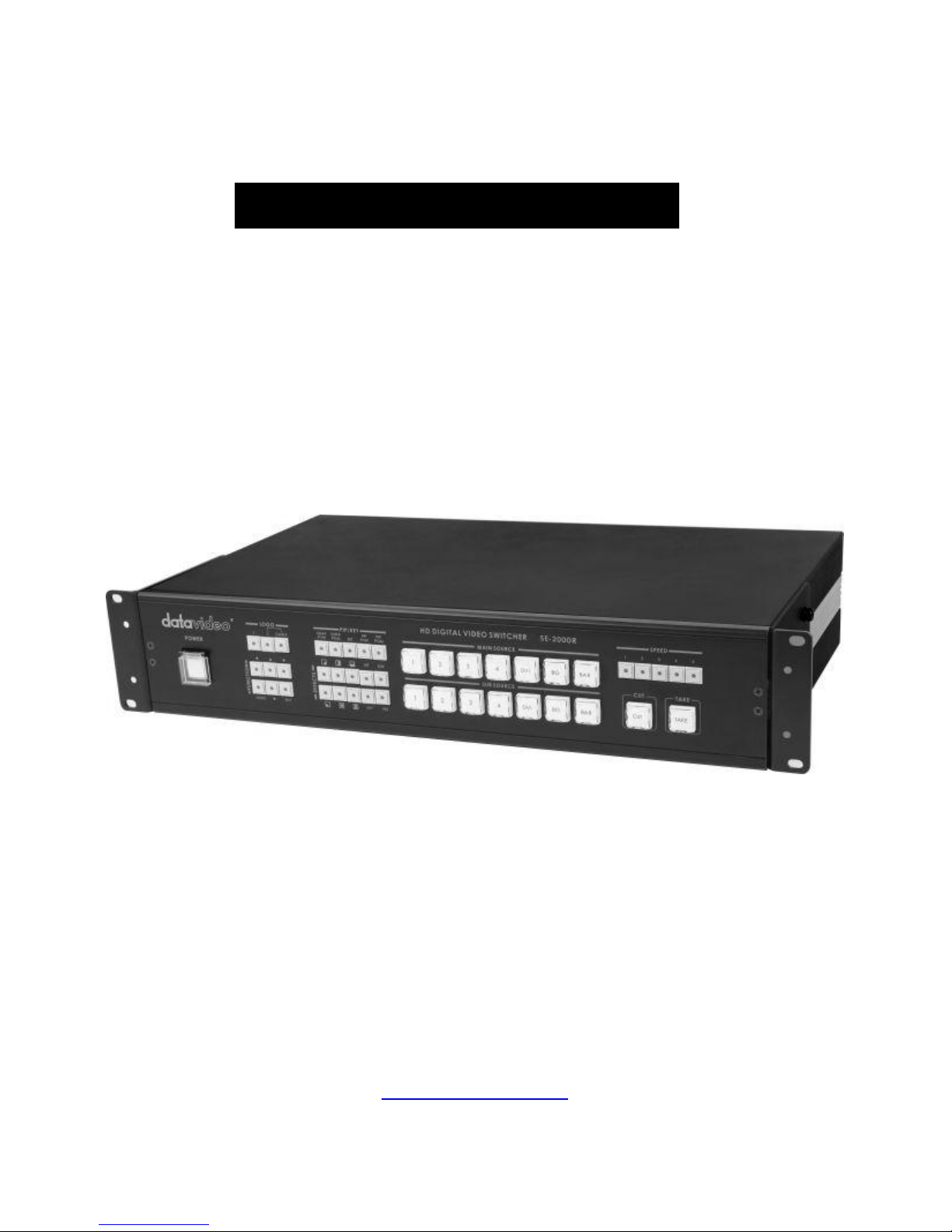
HD Digital Video Switcher
SE-2000R
Quick Start Guide
www.datavideo-tek.com
Page 2

1
Table of Contents
What’s in the box? ...................................................................................................................... 2
Introduction ................................................................................................................................ 2
Product Overview ................................................................ ................................ ....................... 2
Features ..................................................................................................................................... 2
Front Panel ........................................................................................................................... 3
Rear Panel ........................................................................................................................... 6
System Configuration ................................................................................................................. 8
Configuration Utility Service ..................................................................................................... 19
1. Device Setup ................................................................ ................................ .................. 19
2. LOGOS Setup ................................................................................................................ 20
3. Clock Font ...................................................................................................................... 21
4. Background .................................................................................................................... 22
5. Names ............................................................................................................................ 23
Dimension ................................................................................................................................ 24
Specification ............................................................................................................................. 25
Service & Support .................................................................................................................... 26
Page 3

2
What’s in the box?
1 x XLR 4P-F to DC Jack CAD-02
1 x Switching AD DC12V/1.5A
1 x SE-2000R Instruction Manual
Introduction
Thank you for purchasing SAE-2000R Digital Video Switcher. We hope you will be pleased with your purchase,
and with what you can achieve with this advanced piece of technology. In order to get the most out of your new
switcher, we recommend that you spend some time getting familiar with this manual, as it will describe in detail all
the functions of this unit. In addition, you’ll find some useful background information on video.
Product Overview
The SE-2000R is an HD input, digital processing live video switcher. The SE-2000R includes 6 groups of video
inputs (4x BNC connector for HD -SDI & 2 x DVI), and 4 x video outputs PGM (2x HD-SDI output, 1x HD-YUV
output, and, PVW (1x DVI-D output), PVW output include 6x monitoring screen and 1x PVW screen and 1x PGM
screen. These allow easy monitoring of inputs and/or outputs. A built in frame synchroniser ensures glitch free
switching of non synchronised inputs. Additional sockets include, Tally light output, RS-232 interface for firmware
update.
Features
FULL HD:
Input:
4x HD-SDI and 1x DVI-D input or 3x HD-SDI, and 2x DVI-D input (Options)
Output:
PGM: Full HD output, HD-SDI and HD-YUV format
PVW: DVI-D
PVW out with multi image and digital clock display
DVI-D for power point presentation, simple title, support full HD input.
LOGO insertion, up to 14 logos pre-store and LOGO’s size is 256x192 pixels
LUMA key
PIP, FRZ, Black image
5 individual speed keys for instant selection with take effect
5 users preset memory
Tally output
RS-232 control
DC 12V input
13 Transition effect + soft border
Page 4
3
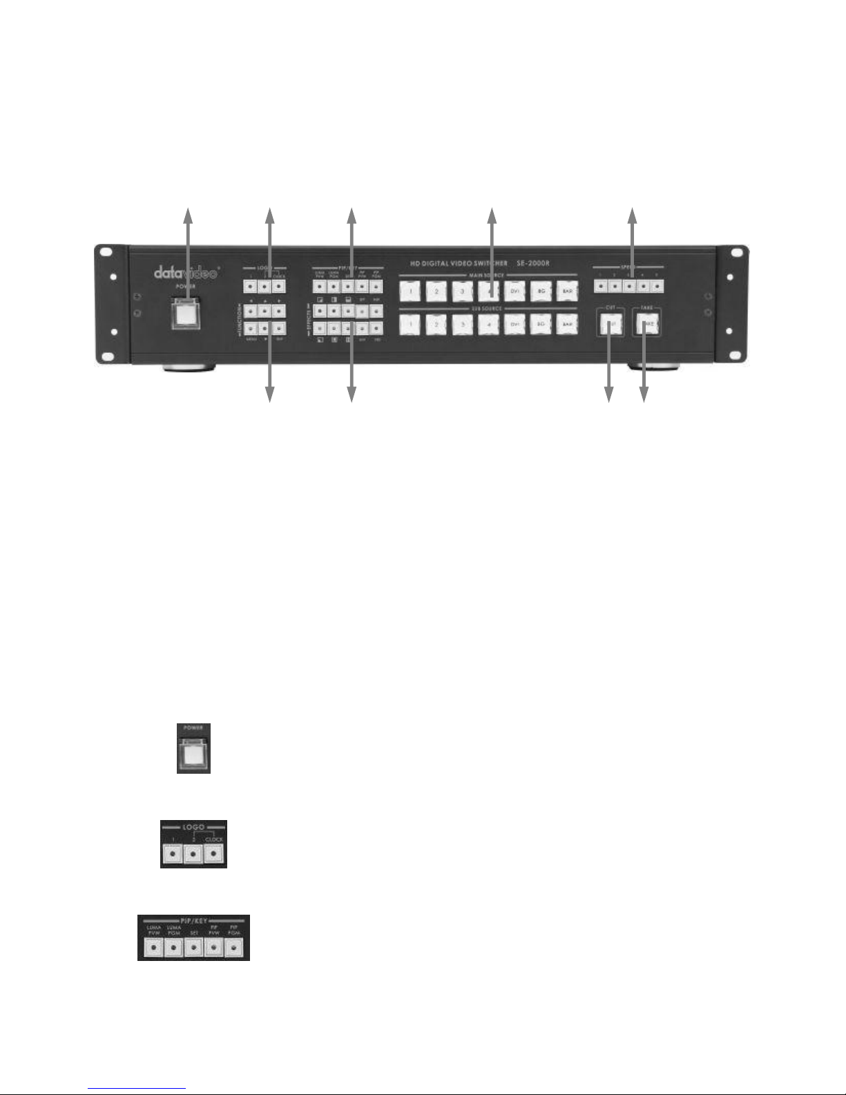
Front Panel
POWER
Switches the power On / Off.
Logo Setting
Select SE-2000R Logo1, Logo2 or Clock Functions on the screen.
LUMA PVW / LUMA PGM
Step 1: Select LUMA source from sub source.
Step 2: Press LUMA PVW or LUMA PGM key.
This function only key LUMA on the PVW or PGM display channel.
1. Power
2. Logo Setting
3. LUMA PVW / LUMA PGM
4. Main / Sub Source
5. Effect Speed
6. TAKE
7. CUT
8. Video Effects
9. Menu and Controls
Page 5
4
SET
SET key function: press SET key → press INV key → press ENTER key.
This function is retrieves previous resolution mode of output signal to multi
screen in case when the monitor doesn’t support a new mode selected from
SE-2000R MENU.
PIP PVW / PIP PGM
Step 1: Press SET key.
Step 2: Press PIP PVW key.
Step 3: Select PIP source from sub source CH1~4.
Step 4: Press PIP PVW or PIP PGM key.
This function is show PIP window on the PVW or PGM display channel.
PIP effect, which stands for Picture in Picture, you can set different sizes and
position.
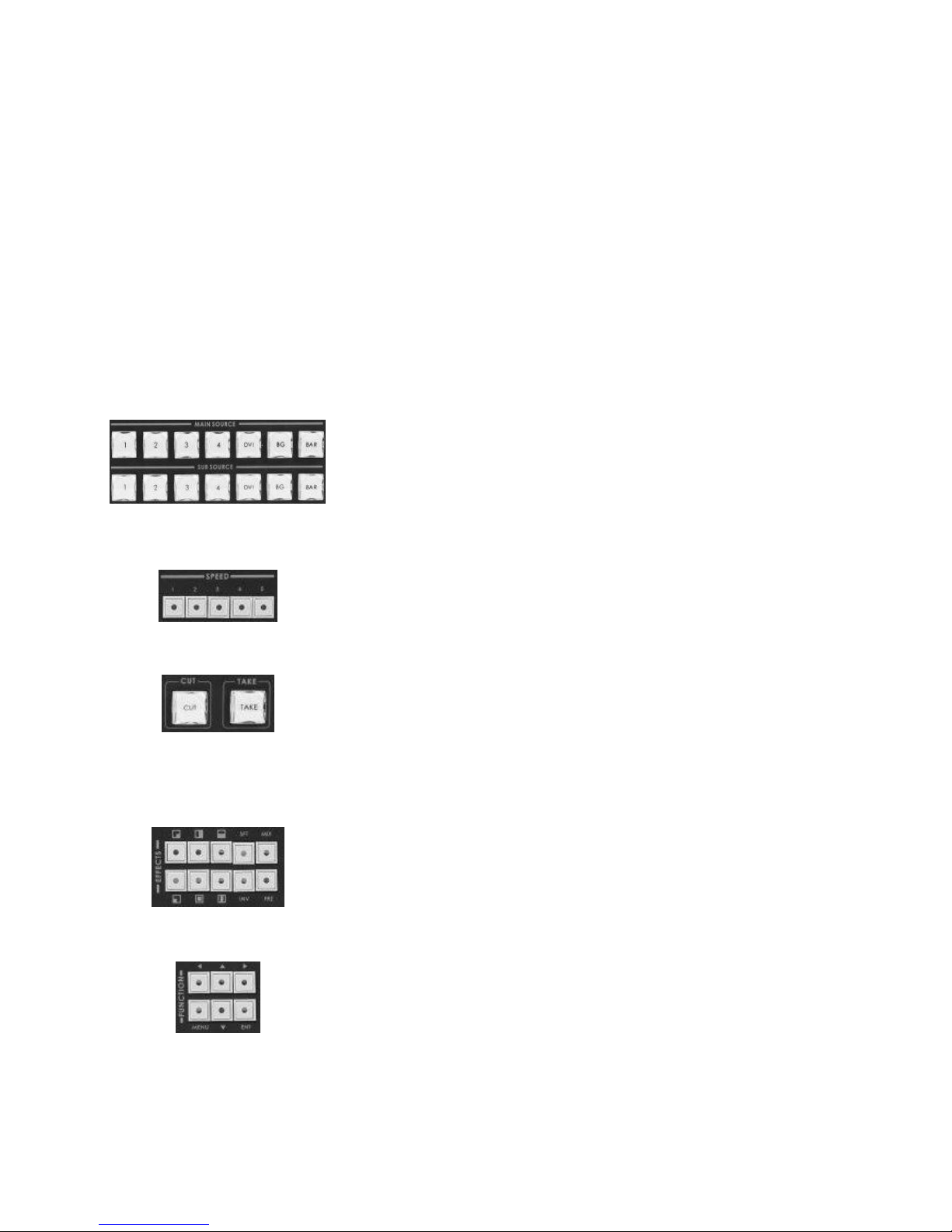
Main Source
Used to select which of the four video input channels or background is sent
to the Main video output. For more information, see Video Source (Page 6).
Sub Source
Used to select which of the four video input channels or background will be
ransitioned to or used as a sub source in an effect.
Effect Speed
Selectable of five different speeds for transition effect.
CUT
Change the main/sub source immediately.
TAKE
Take the effect by preset speed.
Video Effects
10 effect keys, for more information, see Transition Effects (Page 6).
Menu and Controls
Menu button is SE-2000R functions configuration and setting, press the up,
down, left, right arrow button move to another control, and ENT button to
confirm the setting.
Page 6
5
Video Source
Selecting the Main and Sub Video Sources is the first thing to do when setting up the SE-2000R.
The source you select (by pressing one of the buttons; a bright red LED on the selected button lights for
confirmation) on the Main Source bus is what is sent to the Video output. This means that you can perform cuts
between sources by simply pressing different buttons.
The Sub Source selection determines which input will be transitioned to when using any of the transition controls
and provides the video for Picture in Picture and Chroma Key functions.
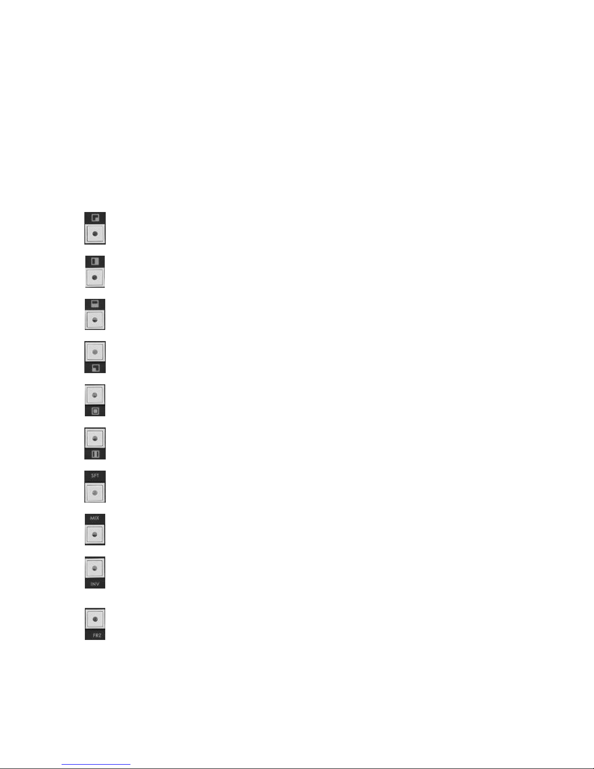
Transition Effects (Reversible)
Right Down to Left High / Left High to Right Down
Right to Left / Left to Right
Top to Bottom / Bottom to UP
Left Down to Right High / Right High to Left Down
Inside Out / Outside In
Middle extend U/D / Middle extend L/R
Controls the border softness of the effect transforming.
Also known as a fade, is a transition wherein all the pixels of one source are replaced by all the
pixels of another, at a smooth rate, and at the same time.
Inverse effect move way.
Press the button once and the video freezes, press it again, and it returns to the selected
source in full motion.
Page 7
6
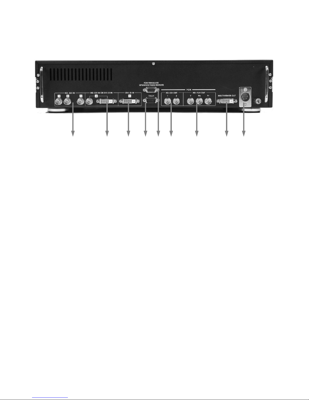
Rear Panel
1. HD- SDI IN
2. HD- SDI IN / DVI-D IN
3. DVI-D IN
4. TALLY
5. RS-232
6. HD- SDI OUT
7. HD- SDI YUV OUT
8. MULTIVIEWER OUT
9. DC IN
Page 8
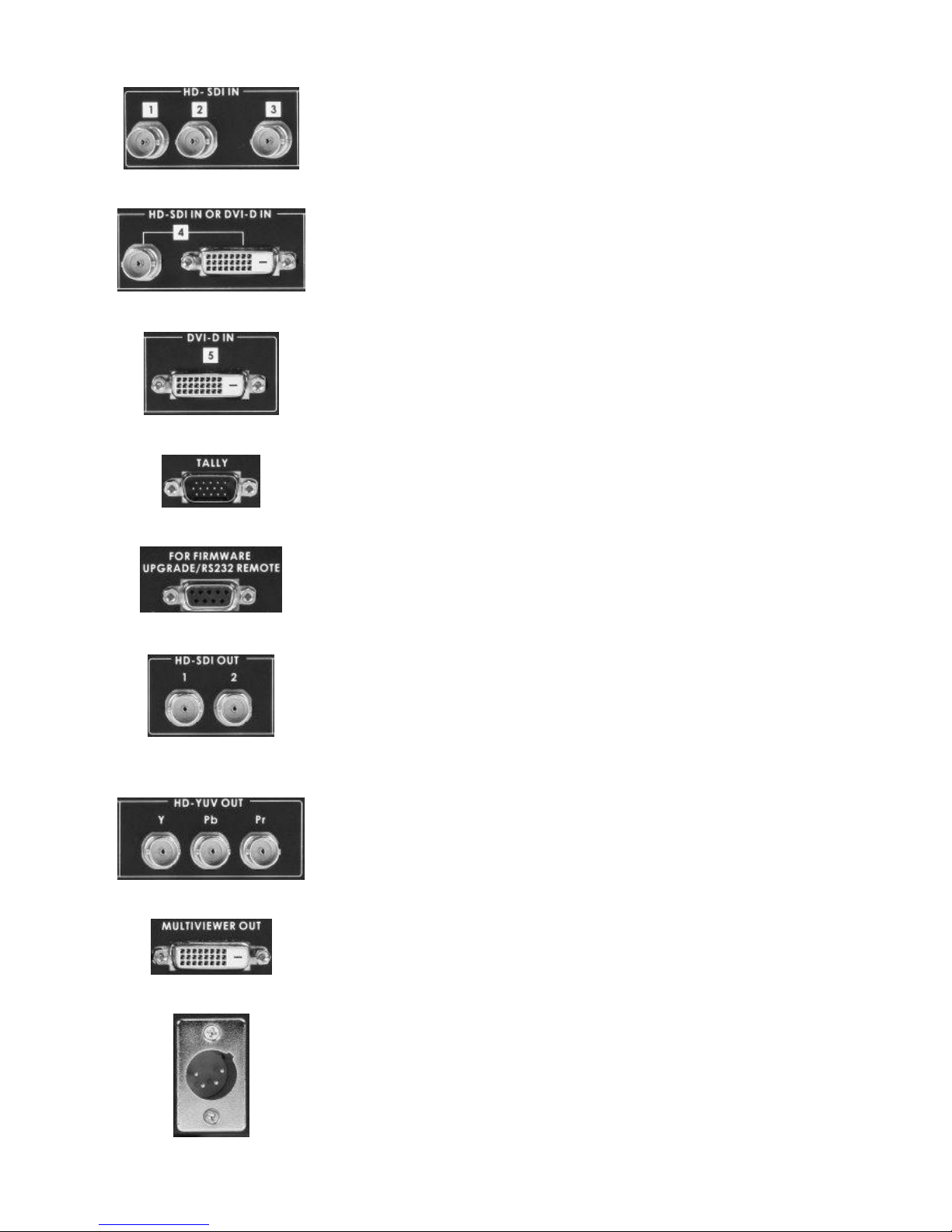
7
HD- SDI IN
HD SDI Signal Input (Digital Inputs 1 to 3).
HD- SDI IN / DVI-D IN
The digital Inputs 4 has two kinds of digital modes for use (HD-SDI & DVI) you
can select the mode in MENU function.
For more information, see INPUT 4 MODE (Page 14).
DVI-D IN
DVI-I Signal Input (Digital Input 5).
TALLY
Tally out socket. This supplies tally light information up to seven buttons of
main source, and other seven button of sub source.
RS-232
9-pin serial port standard RS-232 interface.
Connect PC to update firmware.
HD- SDI OUT
4:2:2 SDI Video data supports SMPTE 292M standard at 1.5G Mbps.
SDI transfers professional level video signals and it’s can connect to long
distance transmission systems.
HD- YUV OUT
HD- YUV component analogue output connecters.
MULTIVIEWER OUT
DVI-D digital signal preview output connecter (PVW).
DC IN
DC in socket connect the supplied 12V 5A PSU to this socket. The connection
can be secured by screwing the outer fastening ring of the DC In plug to the
socket.
Page 9

8
System Configuration
Press on the MENU button for system configuration, press the UP, DOWN, LEFT, RIGHT
button to select an item and press the ENT to confirm the setting.
1. USER’S PROFILE
- Press the MENU button and select item 1 for USER’S PROFILE.
- Press the arrows button to select an item and press the ENT to confirm the setting.
- 6 sets group (0~5) of user’s setting and recall.
* After SE-2000R firmware upgrade, you need to reload your (logo, background, name…etc) files to SE-2000R.
USER’S PROFILE
0 ~ 5
INTPUT SETTINGS
PIP SETTING
LUMA SETTINGS
LOGOS
MODE SETTING
MONITOR MODE
INPUT 4 MODE
MASTER USER SETTING
SOFT EDGE
AUTO TAKE SPEED
BACKGROUND
BLACK & BARS POS.RIGHT
FACTORY SETTINGS
CLOCK SETTINGS
Page 10

9
2. INTPUT SETTINGS
- Press the MENU button and select item 2 for INTPUT SETTINGS.
- Press the arrows button to select an item and press the ENT to confirm the setting.
- BRIGHTNESS: adjustment range from -7 to +7
- CONTRAST: adjustment range from -7 to +7
- SATURATION: adjustment range from -7 to +7
USER’S PROFILE
INTPUT SETTINGS
BRIGHTNESS
-7 ~ +7
CONTRAST
-7 ~ +7
SATURATION
-7 ~ +7
MASTER USER SETTING
●
PIP SETTINGS
LUMA SETTINGS
LOGOS
MODE SETTING
MONITOR MODE
INPUT 4 MODE
MASTER USER SETTING
SOFT EDGE
AUTO TAKE SPEED
BACKGROUND
BLACK & BARS POS.RIGHT
FACTORY SETTINGS
CLOCK SETTINGS
Page 11

10
3. PIP SETTING
- Press the MENU button and select item 3 for PIP SETTING.
- Press the arrows button to select an item and press the ENT to confirm the setting.
- X- POSITION: adjustment range from 0 to 102(under 1080i)
- Y- POSITION: adjustment range from 113 to 0(under 1080i)
- X- POSITION: adjustment range from 0 to 70(under 720p)
- Y- POSITION: adjustment range from 77 to 0(under 720p)
- PIP SIZE: adjustment range from +1 to 33
- The PIP windows will display on preview and program, where are the PIP displayed on, is dependent on
your setting.
USER’S PROFILE
INTPUT SETTINGS
PIP SETTING
PIP POSITION
X- POSITION
0~102
Y- POSITION
0~113
PIP SIZE
1~33
MASTER USER SETTING
●
LUMA SETTINGS
LOGOS
MODE SETTING
MONITOR MODE
INPUT 4 MODE
MASTER USER SETTING
SOFT EDGE
AUTO TAKE SPEED
BACKGROUND
BLACK & BARS POS.RIGHT
FACTORY SETTINGS
CLOCK SETTINGS
Page 12

11
4. LUMA SETTINGS
- Press the MENU button and select item 4 for LUMA SETTINGS.
- Press the arrows button to select an item and press the ENT to confirm the setting.
- LUMA LEVEL: adjustment range from 0 to 255
- The PIP windows will display on preview and program, where are the PIP displayed on, is dependent on
your setting.
USER’S PROFILE
INTPUT SETTINGS
PIP SETTING
LUMA SETTINGS
LUMA LEVEL
0~255
MASTER USER SETTING
●
LOGOS
MODE SETTING
MONITOR MODE
INPUT 4 MODE
MASTER USER SETTING
SOFT EDGE
AUTO TAKE SPEED
BACKGROUND
BLACK & BARS POS.RIGHT
FACTORY SETTINGS
CLOCK SETTINGS
Page 13

12
5. LOGOS
- Press the MENU button and select item 5 for LOGOS.
- Press the arrows button to select an item and press the ENT to confirm the setting.
- SELECT LOGO 1: 14 types (1~14) logo for user’s setting on LOGO1.
- SELECT LOGO 2: 14 types (1~14) logo for user’s setting on LOGO2.
- X- POSITION: adjustment range from 000 to 102(under 1080i)
- Y- POSITION: adjustment range from 110 to 000(under 1080i)
- X- POSITION: adjustment range from 000 to 62(under 720p)
- Y- POSITION: adjustment range from 130 to 000(under 720p)
- The LOGOS will display on preview and program, where are the LOGOS displayed on, is dependent on
your setting.
USER’S PROFILE
INTPUT SETTINGS
PIP SETTING
LUMA SETTINGS
LOGOS
SELECT LOGO 1
01~14
SELECT LOGO 2
01~14
POSITION LOGO 1
X-POSITION
000~102
Y-POSITION
000~110
POSITION LOGO 2
X-POSITION
000~102
Y-POSITION
000~110
CLOCK POSITION
X-POSITION
000~102
Y-POSITION
000~110
MASTER USER SETTING
●
MODE SETTING
MONITOR MODE
INPUT 4 MODE
MASTER USER SETTING
SOFT EDGE
AUTO TAKE SPEED
BACKGROUND
BLACK & BARS POS.RIGHT
FACTORY SETTINGS
CLOCK SETTINGS
Page 14

13
6. MODE SETTING
- Press the MENU button and select item 6 for MODE SETTING.
- Press the arrows button to select an item and press the ENT to confirm the setting.
- Mode setting is set the input mode.
- Please check your input source is what’s mode, and then select same mode of SE-2000R.
USER’S PROFILE
INTPUT SETTINGS
PIP SETTING
LUMA SETTINGS
LOGOS
MODE SETTING
1080i 50Hz
●
1080i 60Hz
●
1080i 59.94Hz
●
720p 50Hz
●
720p 60Hz
●
720p 59.94Hz
●
MASTER USER SETTING
●
MONITOR MODE
INPUT 4 MODE
MASTER USER SETTING
SOFT EDGE
AUTO TAKE SPEED
BACKGROUND
BLACK & BARS POS.RIGHT
FACTORY SETTINGS
CLOCK SETTINGS
Page 15

14
7. MONITOR MODE
- Press the MENU button and select item 7 for MONITOR MODE.
- Press the arrows button to select an item and press the ENT to confirm the setting.
- This mode is setting DVI (preview) output mode, you can select Phase on 1080i or 720p.
8. INPUT 4 MODE
- Press the MENU button and select item 8 for INPUT 4 MODE.
- Press the arrows button to select an item and press the ENT to confirm the setting.
- This mode is setting INPUT 4 format is SDI in or DVI in.
- When you finish your setting, you will see the changed information between PREVIEW and PROGRAM
on the screen.
USER’S PROFILE
INTPUT SETTINGS
PIP SETTING
LUMA SETTINGS
LOGOS
MODE SETTING
MONITOR MODE
1080i 60Hz
●
720p 60Hz
●
MASTER USER SETTING
●
INPUT 4 MODE
MASTER USER SETTING
SOFT EDGE
AUTO TAKE SPEED
BACKGROUND
BLACK & BARS POS.RIGHT
FACTORY SETTINGS
CLOCK SETTINGS
USER’S PROFILE
INTPUT SETTINGS
PIP SETTING
LUMA SETTINGS
LOGOS
MODE SETTING
MONITOR MODE
INPUT 4 MODE
SDI ●
DVI ●
MASTER USER SETTING
●
MASTER USER SETTING
SOFT EDGE
AUTO TAKE SPEED
BACKGROUND
BLACK & BARS POS.RIGHT
FACTORY SETTINGS
CLOCK SETTINGS
Page 16

15
9. MASTER USER SETTING
- Press the MENU button and select item 9 for MASTER USER SETTING.
- Press the arrows button to select an item and press the ENT to confirm the setting.
- This mode is return SE-2000R USER’S PROFILE (0) to its factory default settings.
10. SOFT EDGE
- Press the MENU button and select item 10 for SOFT EDGE.
- Press the arrows button to select an item and press the ENT to confirm the setting.
- This mode is set size of softer border when the transferring effect and Wipe transition only, and can only
be activated when the Picture in Picture or Wipe control is active.
USER’S PROFILE
INTPUT SETTINGS
PIP SETTING
LUMA SETTINGS
LOGOS
MODE SETTING
MONITOR MODE
INPUT 4 MODE
MASTER USER SETTING
● SOFT EDGE
AUTO TAKE SPEED
BACKGROUND
BLACK & BARS POS.RIGHT
FACTORY SETTINGS
CLOCK SETTINGS
USER’S PROFILE
INTPUT SETTINGS
PIP SETTING
LUMA SETTINGS
LOGOS
MODE SETTING
MONITOR MODE
INPUT 4 MODE
MASTER USER SETTING
SOFT EDGE
1~4
AUTO TAKE SPEED
BACKGROUND
BLACK & BARS POS.RIGHT
FACTORY SETTINGS
CLOCK SETTINGS
Page 17

16
11. AUTO TAKE SPEED
- Press the MENU button and select item 11 for AUTO TAKE SPEED.
- Press the arrows button to select an item and press the ENT to confirm the setting.
- This mode is setting different speeds of transition effect.
12. BACKGROUND
- Press the MENU button and select item 12 for BACKGROUND.
- Press the arrows button to select an item and press the ENT to confirm the setting.
- This mode is set Preview background of the screen.
USER’S PROFILE
INTPUT SETTINGS
PIP SETTING
LUMA SETTINGS
LOGOS
MODE SETTING
MONITOR MODE
INPUT 4 MODE
MASTER USER SETTING
SOFT EDGE
AUTO TAKE SPEED
SPEED 1
004~064
SPEED 2
004~064
SPEED 3
004~064
SPEED 4
004~064
SPEED 5
004~064
BACKGROUND
BLACK & BARS POS.RIGHT
FACTORY SETTINGS
CLOCK SETTINGS
USER’S PROFILE
INTPUT SETTINGS
PIP SETTING
LUMA SETTINGS
LOGOS
MODE SETTING
MONITOR MODE
INPUT 4 MODE
MASTER USER SETTING
SOFT EDGE
AUTO TAKE SPEED
BACKGROUND
1~8
BLACK & BARS POS.RIGHT
FACTORY SETTINGS
CLOCK SETTINGS
Page 18

17
13. BLACK & BARS POS.RIGHT
- Press the MENU button and select item 13 for BLACK & BARS POS.RIGHT.
- Press the arrows button to select an item and press the ENT to confirm the setting.
- This mode is (BLK, BAR) swap position to (1, 2) of main/sub source (set to enable).
14. FACTORY SETTINGS
- Press the MENU button and select item 14 for FACTORY SETTINGS.
- Press the arrows button to select an item and press the ENT to confirm the setting.
- This mode is return SE-2000R USER’S PROFILE (all) to its factory default settings.
USER’S PROFILE
INTPUT SETTINGS
PIP SETTING
LUMA SETTINGS
LOGOS
MODE SETTING
MONITOR MODE
INPUT 4 MODE
MASTER USER SETTING
SOFT EDGE
AUTO TAKE SPEED
BACKGROUND
BLACK & BARS POS.RIGHT
● FACTORY SETTINGS
CLOCK SETTINGS
USER’S PROFILE
INTPUT SETTINGS
PIP SETTING
LUMA SETTINGS
LOGOS
MODE SETTING
MONITOR MODE
INPUT 4 MODE
MASTER USER SETTING
SOFT EDGE
AUTO TAKE SPEED
BACKGROUND
BLACK & BARS POS.RIGHT
FACTORY SETTINGS
●
CLOCK SETTINGS
Page 19

18
15. CLOCK SETTINGS
- Press the MENU button and select item 15 for CLOCK SETTINGS.
- Press the arrows button to select an item and press the ENT to confirm the setting.
- This mode is set the clock of the screen.
USER’S PROFILE
INTPUT SETTINGS
PIP SETTING
LUMA SETTINGS
LOGOS
MODE SETTING
MONITOR MODE
INPUT 4 MODE
MASTER USER SETTING
SOFT EDGE
AUTO TAKE SPEED
BACKGROUND
BLACK & BARS POS.RIGHT
FACTORY SETTINGS
CLOCK SETTINGS
SET HOURS
00~23
SET MINUTES
00~59
CLEAR SECONDS
●
Page 20

19
Configuration Utility Service
Computer platform: Windows XP
Installation: SE2000SetupService.exe
Default Installation Directory: С:\Program Files\SE2000 Setup Service
Add and Remove Programs: SE2000 Configuration Utility Service, Uninstall
1. Device Setup
Connect SE2000 to PC COM port
Open “SE2000 Configuration Utility Service” tools
If connection is correct appear window:
If model is not appointed, change Serial (COM) port
Page 21

20
2. LOGOS Setup
Logo source please use 256 х192 pixels, TGA 32bit or BMP 24 bit files with α- channel
α- channel can be obtain from pair of bmp files, see picture below:
Step by step:
1. Open “SE2000 Configuration Utility Service” tools
2. Select bookmark: Logos
3. Load file: 256 х192 pixels, TGA 32bit or BMP 24 bit files
4. Write to the Slot you need.
Note: If you use the pair of BMP files, only one file can be selected – the Config program add second file
automatically.
Note: When you upgrade SE-2000R, The Datavideo logo will reappear.
Page 22

21
3. Clock Font
Clock Source Files: 128 х96 pixels, TGA 32bit or BMP 24 bit files with α- channel
α- channel can be obtain from pair of bmp files, see picture below:
Step by step:
1. Open “SE2000 Configuration Utility Service” tools
2. Select bookmark: Clock font
3. Load file 256 х192 pixels, TGA 32bit or BMP 24 bit files with α- channel
4. Write to the output parts you need.
Note: If you use the pair of BMP files, only one file can be selected – the Config program add second file
automatically .
Page 23

22
4. Background
Background Source Files: 128 х128 pixels, TGA 32bit or BMP 24 bit
Step by step:
1. Open “SE2000 Configuration Utility Service” tools
2. Select bookmark: Background
3. Load file 128 х128 pixels, TGA 32bit or BMP 24 bit
4. Write to the Slot you need.
Page 24

23
5. Names
Name source files consist 2 elements:
1. Inscription Background 192 х32 pixels, TGA 32bit or BMP 24 bit files with α- channel.
2. Key in text label name in spatial window named “Text”.
α- channel can be obtain from pair of bmp files, see picture below:
Step by step:
1. Open “SE2000 Configuration Utility Service” tools
2. Select bookmark: Names
3. Load file 192 х32 pixels, TGA 32bit or BMP 24 bit files with α- channel
4. Select Font you want
5. Type Name
6. Write to the Slot you need.
Note: If you use the pair of BMP files, only one file can be selected – the Config program add second file
automatically.
Page 25

24
Dimension
Page 26

25
Specification
Inputs
• 4x BNC connector for HD -SDI input
• 2x DVI connector for DVI-D input (1x DVI-D input is collective with SDI#4 channel)
Outputs
• 2x HD-SDI output, 1x HD-YUV output, and 1x DVI-D output
Video Input
• HD (1080/50i -1080/60i -1080/59.94i -720/50p -720/60p -720/59.94p)
Multi view
output
• 1x DVI-D output
• Multi screen display include 6 x monitoring screen(include 1 x PIP) and 1x PVW screen
and 1x PGM screen
• Resolution is 1280 x 720, 1920x1080
Other
Interface
• Serial (Editor) D-Sub 9 Pin x 1 RS232
• Tally Output D-Sub 15 Pin x 1 14 Channel Open Collector Output
• Support Line and MIC mode
HD SDI signal
• SMPTE 292M standard complied with
• Output return loss : More than 15 dB (5MHz to 750MHz) More than 10 dB (750MHz to 1.5
GHz)
• Output level : 0.8 Vpp ± 10%
• Rise time : Less than 270 ps
• Fall time : Less than 270 ps
• Difference between rise time and fall time within 100 ps
• Alignment jitter : Less than 0.2 UI
• Timing jitter : Less than 1.0 UI
• Eye aperture ratio : More than 90%
• DC offset : 0 ± 0.5V
• Equalizer use 5C-FB cable support 100 meters
HD-YUV
Output
• Bandwidth 30MHz < +/-3dB
• S/N Ratio > 50 dB
• DG <3%, DP <3 degree ( Base on U, V signal analyzer)
Operating
Temperature
• 0°C to 40°C (32°F to 102°F)
Humidity
• 10% to 90% (non condensing)
Dimension &
Weight
• 425mm (W) x 400mm (D) x 96mm (H) / 4Kgs
Power
• Input AC 100 ~ 240V Switching Adaptor, output DC 12V / 17W
Page 27

26
Service & Support
It is our goal to make your products ownership a satisfying experience. Our supporting staff is available to assist
you in setting up and operating your system. Please refer to our web site www.datavideo-tek.com for answers to
common questions, support requests or contact your local office below.
Datavideo Global Website: www.datavideo-tek.com
Datavideo Corporation
Tel: +1 562 696 2324
Fax: +1 562-698-6930
E-Mail: contactus@datavideo.us
Datavideo Technologies Europe BV
Tel: +31-30-261-96-56
Fax: +31-30 261-96-57
E-Mail: service@datavideo.nl
Datavideo UK Limited
Tel: +44 1457 851 000
Fax: +44 1457 850 964
E-Mail: sales@datavideo.co.uk
Datavideo Technologies Co., Ltd
Tel: +886 2 8227 2888
Fax: +886-2-8227-2777
E-mail: service@datavideo.com.tw
Datavideo Technologies China Co., Ltd
Tel: +86 21-5603 6599
Fax:+86 21-5603 6770
E-mail: service@datavideo.cn
Datavideo Technologies (S) PTE LTD
Tel: +65-6749 6866
Fax: +65-6749 3266
E-mail: service@datavideo.sg
Datavideo HK Limited.
Tel: +852 2833 1981
Fax: +852-2833-9916
E-mail: info@datavideo.com.hk
Datavideo France
Tel: +33 1 60 37 02 46
Fax: +33 1 60 37 67 32
E-Mail: jean-marie.huet@datavideo.fr
Datavideo India
Tel: +91 120 4309120
Fax: +91 120 4309121
E-Mail: sales@datavideo.in
All the trademarks are the properties of their respective owners.
Datavideo Technologies Co., Ltd. All rights reserved 2018
P/N: G082060626B1
 Loading...