

Datavideo SE-1200MU Quick Start Manual

1

2
Contents
Warnings and Precautions ................................................................................................................................................... 5
Warranty .............................................................................................................................................................................. 6
Disposal ................................................................................................................................................................................ 6
Packing List ........................................................................................................................................................................... 6
Front Panel ........................................................................................................................................................................... 7
Rear Panel ............................................................................................................................................................................ 7
Hardware Connection Setup ................................................................................................................................................ 8
Connection of the SE-1200MU and PC to ROUTER .......................................................................................................... 8
Menu Select ......................................................................................................................................................................... 9
SETUP Key Functions ........................................................................................................................................................ 9
Setting the Resolution.................................................................................................................................................. 9
Software Upgrade ...................................................................................................................................................... 10
Import – Export .......................................................................................................................................................... 11
INPUTS Key Functions .................................................................................................................................................... 18
Setting Video Inputs ................................................................................................................................................... 18
OUTPUTS Key Functions ................................................................................................................................................ 20
Setting Video Outputs ................................................................................................................................................ 20
Setting MultiViewer ................................................................................................................................................... 20
Setting GPI Out........................................................................................................................................................... 21
Setting Streamer ........................................................................................................................................................ 21
AUDIO Key Functions ..................................................................................................................................................... 24
HOME Key Functions ..................................................................................................................................................... 25
ME Trans .................................................................................................................................................................... 25
DSK Trans ................................................................................................................................................................... 25
FTB Trans .................................................................................................................................................................... 25
WIPE Key Functions ....................................................................................................................................................... 25
Wipe ........................................................................................................................................................................... 27
Wipe Border ............................................................................................................................................................... 27
Wipe Shade ................................................................................................................................................................ 28
Wipe Position ............................................................................................................................................................. 30
STILLS Key Functions ...................................................................................................................................................... 30
Still Load ..................................................................................................................................................................... 30
Grab and Save ............................................................................................................................................................ 32
Delete ......................................................................................................................................................................... 32
KEYER Key Functions ...................................................................................................................................................... 33
Keyer Control ............................................................................................................................................................. 33
Keyer Matte ............................................................................................................................................................... 33

3
Luma Key Quick Set Up .............................................................................................................................................. 34
DSK1 and DSK2 Quick Setup ...................................................................................................................................... 35
SE-1200 MU Keying layers ......................................................................................................................................... 36
CHROMA Key Functions ................................................................................................................................................. 37
Overview .................................................................................................................................................................... 37
Chroma Matte ............................................................................................................................................................ 39
Chroma Key Ctrl ......................................................................................................................................................... 39
Color Spill ................................................................................................................................................................... 40
Chroma Key Quick Setup ........................................................................................................................................... 42
MASK Key Functions ...................................................................................................................................................... 43
MATTE Key Functions .................................................................................................................................................... 45
FREEZE Key Functions .................................................................................................................................................... 46
Freeze – Still ............................................................................................................................................................... 47
P IN P Key Functions ...................................................................................................................................................... 50
PIP Position ................................................................................................................................................................ 50
PIP Border .................................................................................................................................................................. 51
PIP Crop ...................................................................................................................................................................... 52
USER Key Functions ....................................................................................................................................................... 53
Storing an user setup to a user memory slot ............................................................................................................. 53
Labelling an existing User memory slot ..................................................................................................................... 53
Loading a previously saved User Setup ..................................................................................................................... 54
Deleting a User Setup ................................................................................................................................................ 56
Sources Panel ..................................................................................................................................................................... 57
AUX BUS ......................................................................................................................................................................... 57
PROGRAM ...................................................................................................................................................................... 57
PRESET ........................................................................................................................................................................... 57
Transition ........................................................................................................................................................................... 58
Transition Panel ............................................................................................................................................................. 58
Transition Modes ....................................................................................................................................................... 58
Mix Button ..................................................................................................................................................................... 58
Wipe Button ................................................................................................................................................................... 58
Cut Button ...................................................................................................................................................................... 58
Auto Button ................................................................................................................................................................... 58
Previewing a selected transition ................................................................................................................................ 58
Transition Controls Panel ............................................................................................................................................... 59
Key 1 and Key 2 .......................................................................................................................................................... 59
BGND – Background ................................................................................................................................................... 60
PRIORITY Key Function ............................................................................................................................................... 60

4
Rev and Nrm (NORM) / Rv (REV) buttons .................................................................................................................. 60
DSK TRANS Panel ........................................................................................................................................................... 60
FTB Key Function ............................................................................................................................................................ 61
Keyer Controls Panel .......................................................................................................................................................... 62
Matte Key Function........................................................................................................................................................ 62
Lin Key Function ............................................................................................................................................................. 62
Top Key Function ........................................................................................................................................................... 62
Self Key Function ............................................................................................................................................................ 62
Split Key Function .......................................................................................................................................................... 62
Specifications ..................................................................................................................................................................... 63
Service & Support .............................................................................................................................................................. 66

5
Warnings and Precautions
1. Read all of these warnings and save them for later reference.
2. Follow all warnings and instructions marked on this unit.
3. Unplug this unit from the wall outlet before cleaning. Do not use liquid or aerosol cleaners. Use a damp cloth for
cleaning.
4. Do not use this unit in or near water.
5. Do not place this unit on an unstable cart, stand, or table. The unit may fall, causing serious damage.
6. Slots and openings on the cabinet top, back, and bottom are provided for ventilation. To ensure safe and reliable
operation of this unit, and to protect it from overheating, do not block or cover these openings. Do not place this
unit on a bed, sofa, rug, or similar surface, as the ventilation openings on the bottom of the cabinet will be blocked.
This unit should never be placed near or over a heat register or radiator. This unit should not be placed in a built-in
installation unless proper ventilation is provided.
7. This product should only be operated from the type of power source indicated on the marking label of the AC
adapter. If you are not sure of the type of power available, consult your Datavideo dealer or your local power
company.
8. Do not allow anything to rest on the power cord. Do not locate this unit where the power cord will be walked on,
rolled over, or otherwise stressed.
9. If an extension cord must be used with this unit, make sure that the total of the ampere ratings on the products
plugged into the extension cord do not exceed the extension cord rating.
10. Make sure that the total amperes of all the units that are plugged into a single wall outlet do not exceed 15
amperes.
11. Never push objects of any kind into this unit through the cabinet ventilation slots, as they may touch dangerous
voltage points or short out parts that could result in risk of fire or electric shock. Never spill liquid of any kind onto
or into this unit.
12. Except as specifically explained elsewhere in this manual, do not attempt to service this product yourself.Opening
or removing covers that are marked “Do Not Remove” may expose you to dangerous voltage points or other risks,
and will void your warranty. Refer all service issues to qualified service personnel.
13. Unplug this product from the wall outlet and refer to qualified service personnel under the following conditions:
a. When the power cord is damaged or frayed;
b. When liquid has spilled into the unit;
c. When the product has been exposed to rain or water;
d. When the product does not operate normally under normal operating conditions. Adjust only those
controls that are covered by the operating instructions in this manual; improper adjustment of other
controls may result in damage to the unit and may often require extensive work by a qualified technician
to restore the unit to normal operation;
e. When the product has been dropped or the cabinet has been damaged;
f. When the product exhibits a distinct change in performance, indicating a need for service.

6
Warranty
Standard Warranty
Datavideo equipment is guaranteed against any manufacturing defects for one year from the date of purchase.
The original purchase invoice or other documentary evidence should be supplied at the time of any
request for repair under warranty.
Damage caused by accident, misuse, unauthorized repairs, sand, grit or water is not covered by this warranty.
All mail or transportation costs including insurance are at the expense of the owner.
All other claims of any nature are not covered.
Cables & batteries are not covered under warranty.
Warranty only valid within the country or region of purchase.
Your statutory rights are not affected.
Two Year Warranty
All Datavideo products purchased after 01-Oct.-2008 qualify for a free one year extension to the
standard Warranty, providing the product is registered with Datavideo within 30 days of purchase. For
information on how to register please visit www.datavideo.com or contact your local Datavideo office or
authorized Distributors
Certain parts with limited lifetime expectancy such as LCD Panels, DVD Drives, Hard Drives are only covered
for the first 10,000 hours, or 1 year (whichever comes first).
Any second year warranty claims must be made to your local Datavideo office or one of its authorized
Distributors before the extended warranty expires.
Disposal
For EU Customers only - WEEE Marking.
This symbol on the product indicates that it will not be treated as household waste. It must
be handed over to the applicable take-back scheme for the recycling of Waste Electrical and
Electronic Equipment. For more detailed information about the recycling of this product, please
contact your local Datavideo office.
Packing List
The following items should be included in the box. If any items are missing please contact your supplier.
1 x SE-1200 Main Unit
1 x SE-1200 MU Quick Start Guide
1 x Accessory List
7
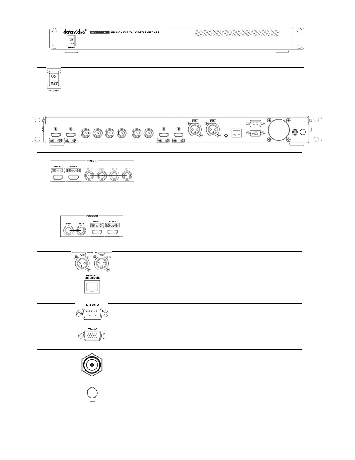
Front Panel
Power Switch
Switches the SE-1200 MU power ON / OFF.
Rear Panel
Video IN
The SE-1200 MU is equipped with six video input channels.
Video Input set is comprised of four SDI connectors and two
HDMI ports.
Note: Both HDMI ports support 1080p only.
Video OUT
HDMI 1: Multi-View Outputs
HDMI 2: Output for engineering debugging
SDI 1 / SDI 2: SE-1200 MU is capable of achieving multi-view
monitoring by connecting two multi-view monitors to the
two SDI ports. The two HDMI outputs can be used for
monitoring video in a number of different configurations.
Audio Input
Supports four channels XLR Balanced Audio Input.
Ethernet Ports
For connection of the Main Unit to the PC such that the SE1200 MU can be remotely controlled on a graphical user
interface.
RS-232
For remote control interface (TBD).
TALLY Output
The SE-2200 MU Tally Output Port provides tri-color tally
information (Red, Yellow and Green); Red indicates On-Air
and Yellow indicates next camera source.
DC IN
Connect the supplied 12V / 19W PSU to this socket. The
connection can be secured by screwing the outer fastening
ring of the DC In plug to the socket.
Grounding Terminal
When connecting this unit to any other component, make
sure that it is properly grounded by connecting this terminal
to an appropriate point. When connecting, use the socket
and be sure to use wire with a cross-sectional area of at least
1.0 mm2.
8
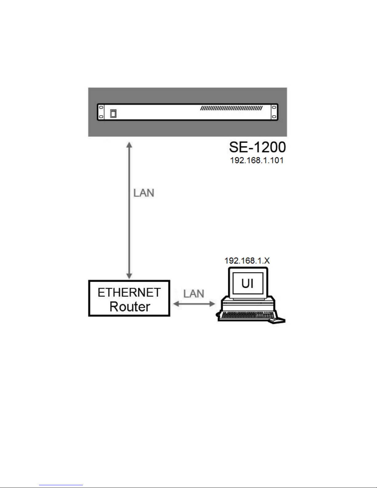
Hardware Connection Setup
Connection of the SE-1200MU and PC to ROUTER
Use Ethernet cable to connect SE-1200 Main unit and PC to a router.
The user can either set the IP address of the PC to
192.168.1.100 or configure the PC to DHCP mode in which the IP address is dynamically assigned by the router. The SE-1200 Main
unit has a default IP address of 192.168.1.101. After all network configurations are completed, the PC and the SE -1200 can
thus communicate across the network. You may need the help of an I.T. specialist to configure your network settings.
9
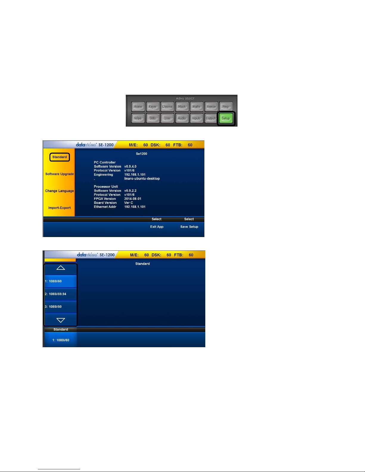
Menu Select
Before start using the SE-1200 MU, the user should locate the MENU SELECT panel on the control panel and configure the basic
settings.
SETUP Key Functions
Setting the Resolution
1. There are six standard resolutions available on the SE-1200 MU. To set the resolution, the user should first click the Setup
button on the MENU SELECT panel.
2. Click on Standard to select the desired resolution
3. Select the desired resolution from the following list:
Click the up/down arrows to scroll through the resolution list and click the desired resolution. After the desired resolution is
selected, the list should automatically disappear, leaving the selected standard resolution displayed at bottom left hand cor ner
of the screen. The connected monitors should now identify and sync with the new resolution output sent from the switcher.
Standard resolutions are:
1920x1080i 60
1920x1080i 59.94
1920x1080i 50
1280x720p 60
1280x720p 59.94
1280x720p 50
10
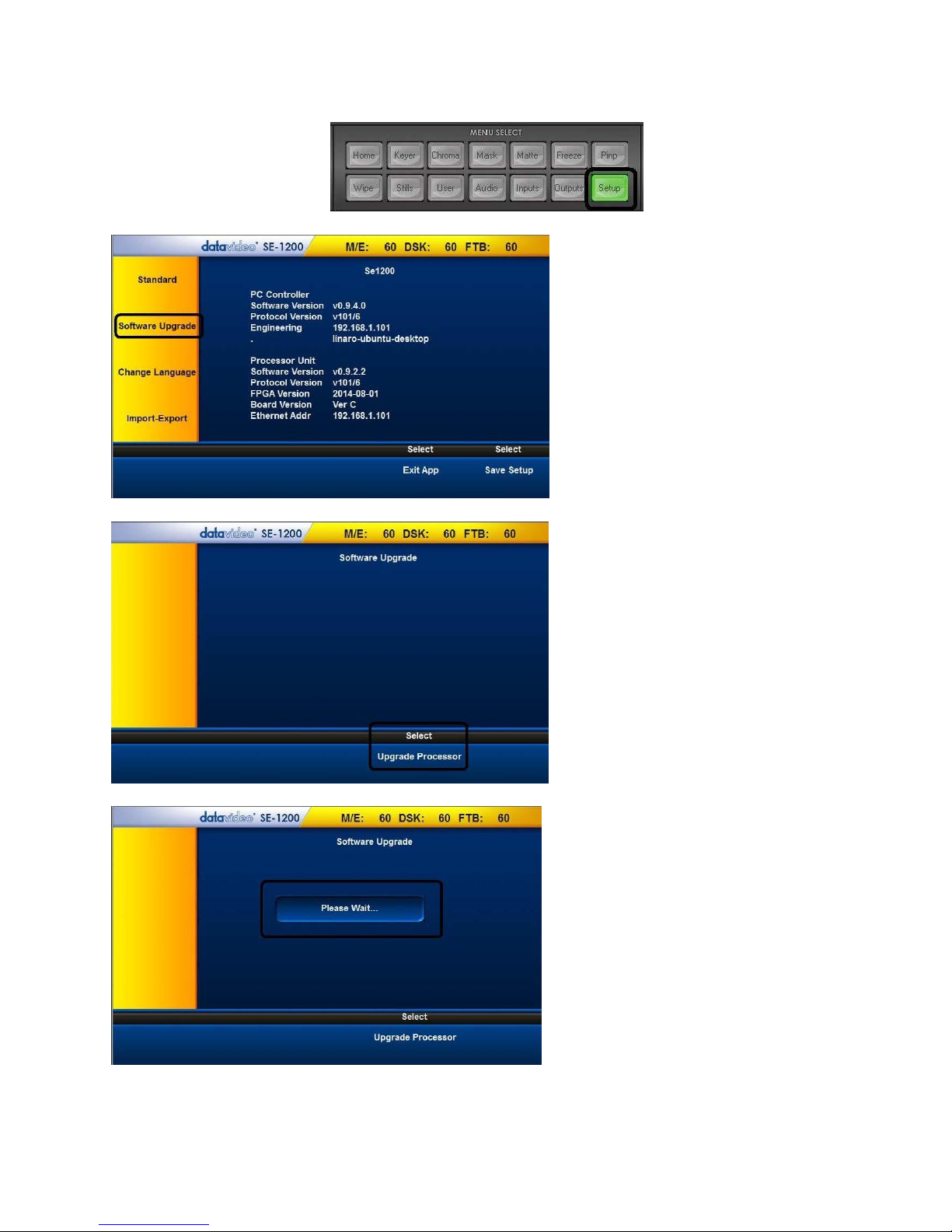
Software Upgrade
The SE-1200 MU also allows the user to perform software upgrade. The software upgrade procedure is outlined as follows:
1. Click the Setup button on the MENU SELECT panel.
2. Click the “Software Upgrade”
3. Click “Upgrade Processor”
4. Wait till the “Please Wait” prompt window disappear
5. Reboot the SE-1200 MU main unit to complete the software upgrade process.
Note: Please contact your local Datavideo office or dealer for the latest SE-1200 MU Firmware and Application Software.
Datavideo regional offices can be found on the last page of this manual.

11
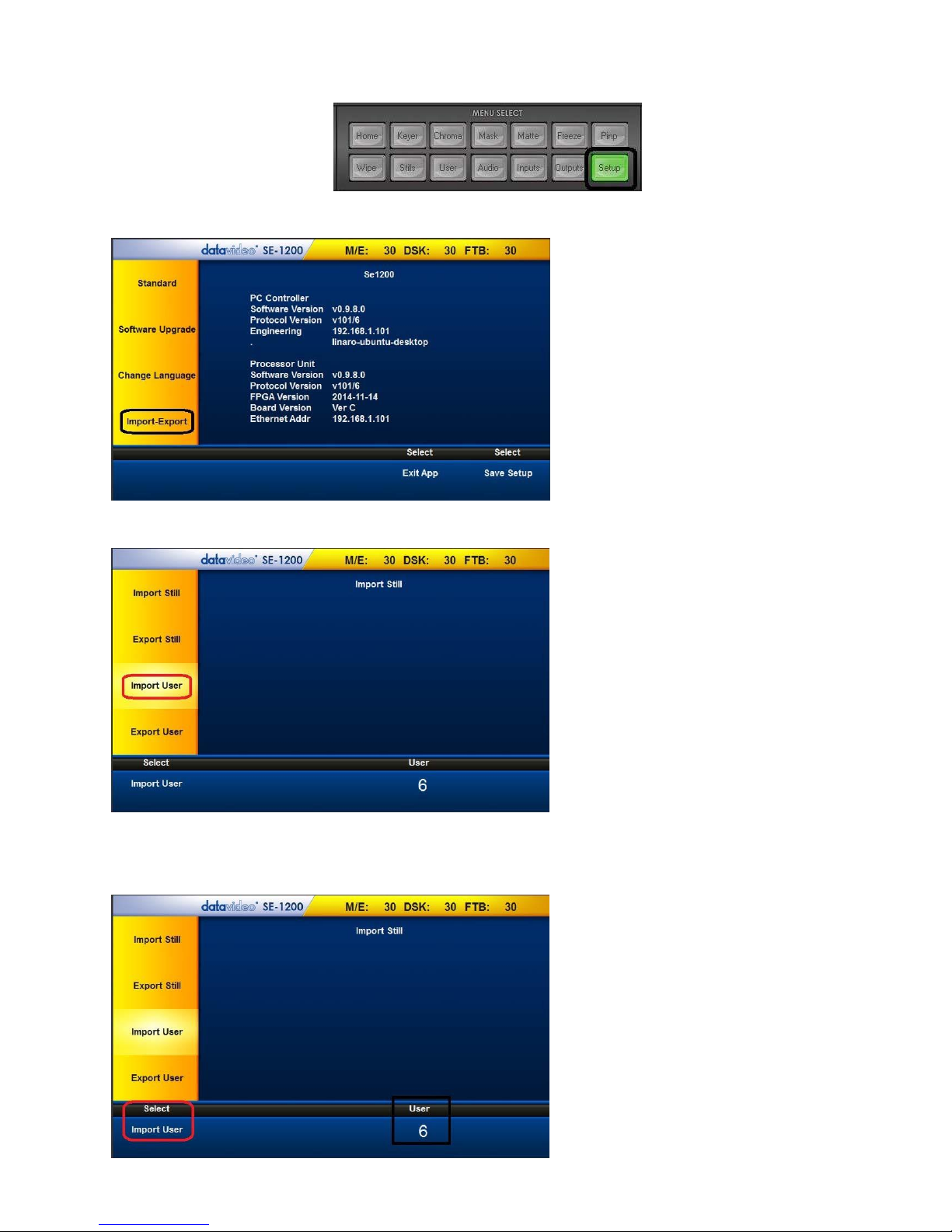
Import – Export
The Import – Export allows you to store and recall various user setups on the SE-1200 MU. Should you have various standard
configurations for the production, the user can use this feature to save the configurations beforehand; to save time, the user can
simply apply the saved configuration during the production. In addition, it eliminates the hassle of reconfiguring the SE-1200 MU
after it is used by another user. The features under this option are Import Still, Export Still, Import User and Export User.
Export Still
1. Click the “Setup” button on the MENU SELECT panel
2. Click “Import-Export” as shown below
3. Click “Export Still” and use the up/down arrows to browse the thumbnails; select a picture
4. Click “Export Still” located at the bottom left hand corner of the screen
12
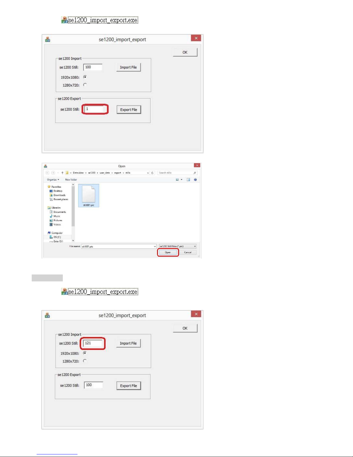
5.
Click the icon to open the SE-1200 Import_Export tool; e
nter the still number and then
click the Export File button.
6. Select a stillxxx.pic file and then click Open button.
Import Still
1. Click the icon to open the SE-1200 import_export tool
2. Enter the still number (121) and then click the Import File button
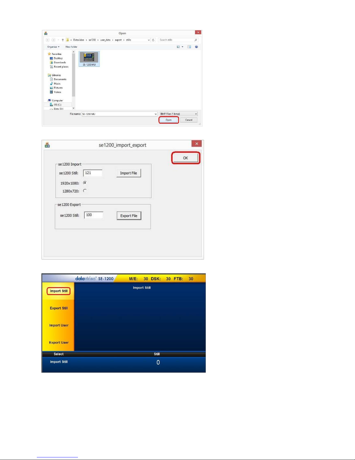
13
3. Select a BMP file and then click Open button
4. Click OK button to save the selected file and exit the import_export tool
5. Open the SE-1200 MU Application and enter Import-Export option; click Import Still as shown below
6. Click “Still” located at the right hand corner of the screen as shown below to open a pop-up window; on the pop-up window,
enter the still number (e.g. 121) and then click the Enter button
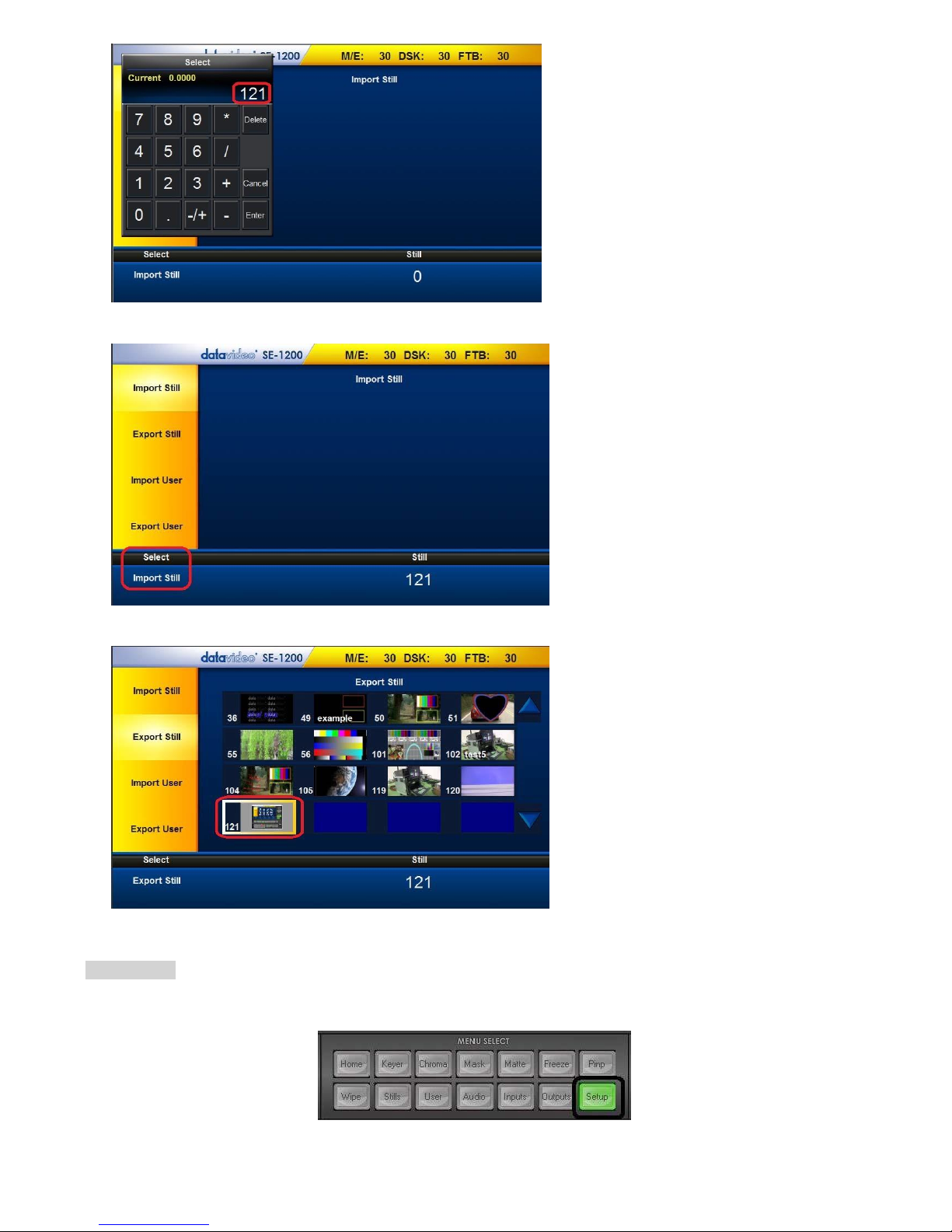
14
7. Click “Import Still” located at the bottom left hand corner of the screen to import the selected file
8. Enter “Export Still” to check the thumbnail of the imported still picture file as shown in the diagram below
Export User
1. Click the “Setup” button on the MENU SELECT panel
2. Click “Import-Export” as shown below
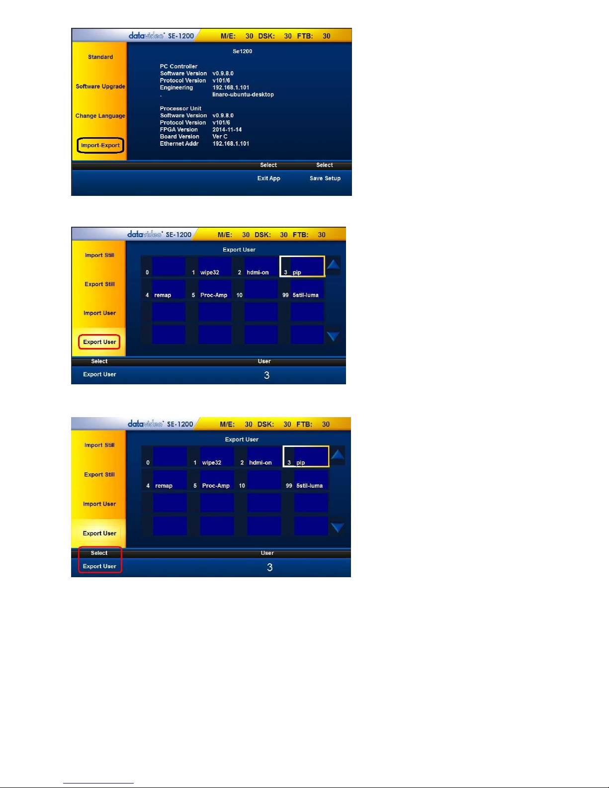
15
3. Click Export User as shown below and use the up/down arrows to browse the saved setups
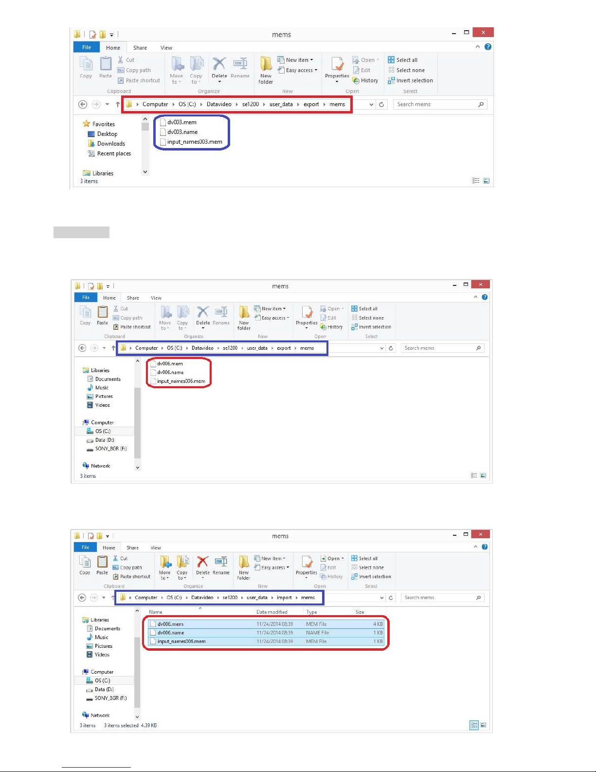
4. Select a Setup and click “Export User” located at the bottom left hand corner of the screen
5. Check the exported files in the directory “C:\Datavideo\se1200\user_data\export\mems”
16
Import User
1. Copy dvXXX.mem, dvXXX.name and input_namesXXX.mem files from the directory
“C:\Datavideo\se1200\user_data\export\mems”
2. Paste the three files into the directory “C:\Datavideo\se1200\user_data\import\mems”
17
3. Click the Setup button on the MENU SELECT panel
4. Click “Import-Export” as shown below
5. Click “Import User" as shown below
6. Click “User” (located at the bottom right hand corner of the screen) to open a pop-up window on which the user is allowed to
enter an Import User number and then click the Enter button; Click Import User (located at the bottom left hand corner of the
screen) to start importing the selected User setup
18
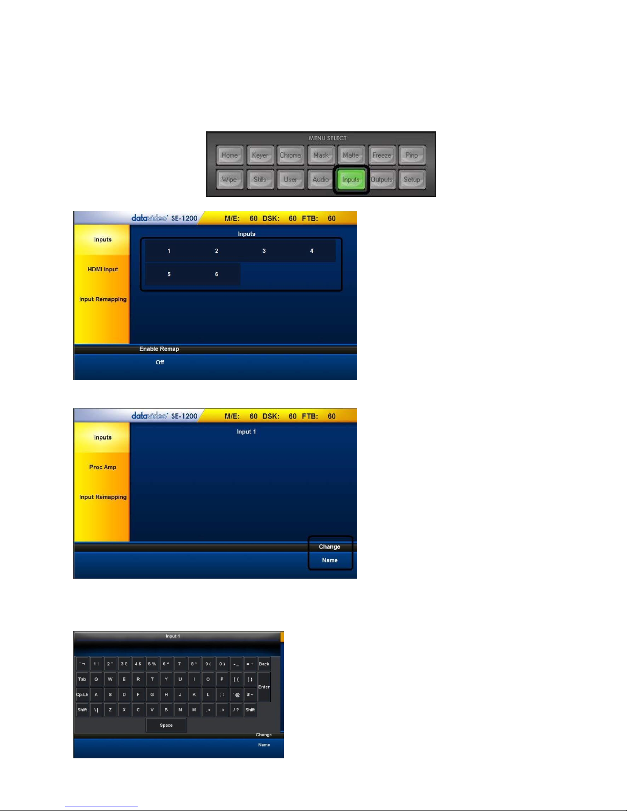
INPUTS Key Functions
Setting Video Inputs
The multiview screens are initially labelled Input 1-6, SDI OUT1 and SDI OUT2 by default. These labels may be changed accordingly
and the label text length is limited to not more than 16 characters.
1. Click the Inputs button on the MENU SELECT panel
2. Select a channel to edit
3. After entering the selected channel, locate and click “Change – Name” at the bottom right hand corner
4. An onscreen keyboard will then be displayed. Enter the desired channel name in the text bar on the onscreen keyboard.
Click on the “Back” button to delete. After the new channel name is entered, click on the “Enter” button and the onscreen
keyboard should disappear. Your new label should now appear on the Multiview Screen.
19
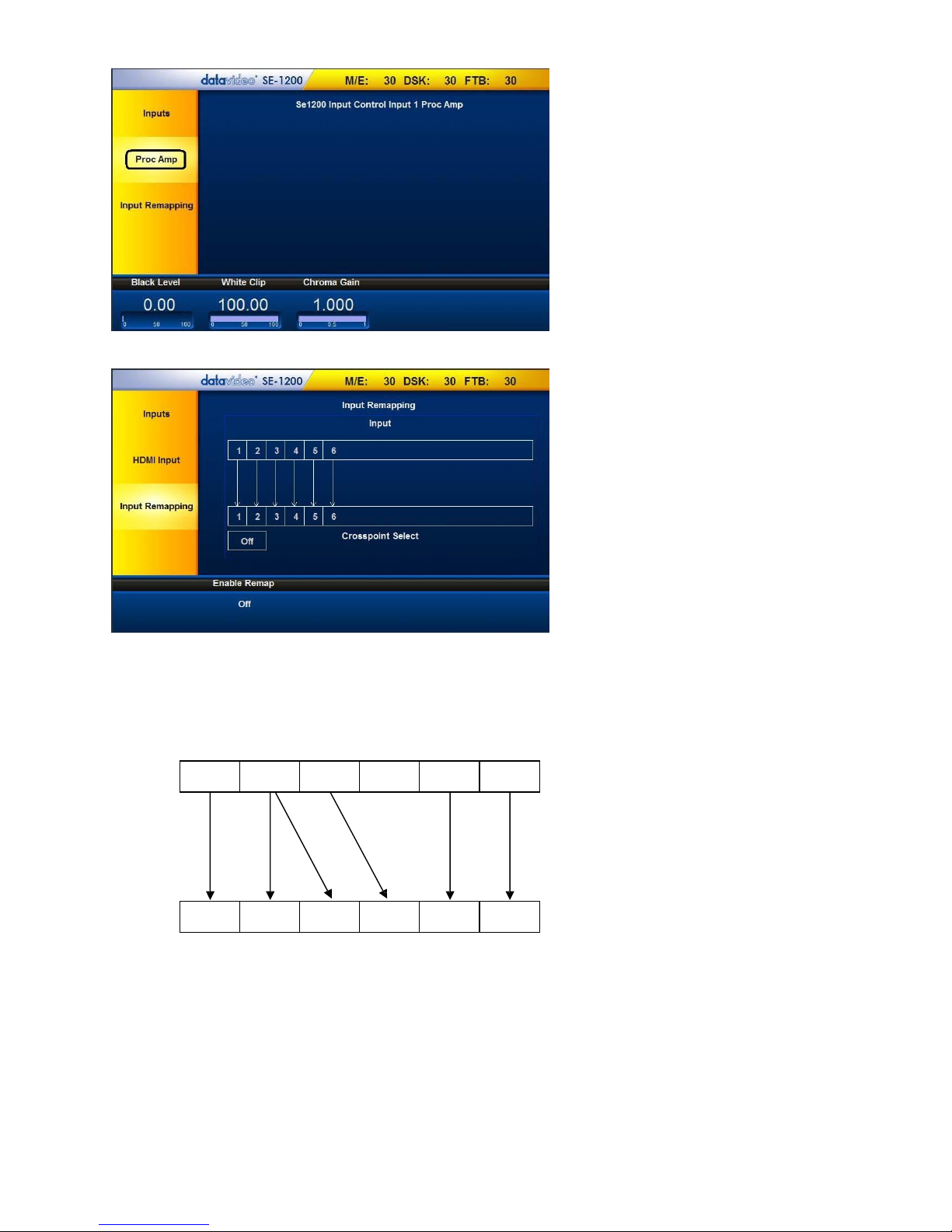
5. Click “Proc Amp” to configure “Black Level”, “White Clip”, and “Chroma Gain” for each input
6. Click the “Inputs Remapping” to set crosspoint
The SE-1200 MU has six input channels, which are mixed in different combinations. In the example illustrated below, the SE1200 MU setting is configured by enabling the desired video input channels and feeding the enabled combination to the
corresponding input channels.
Input Remapping
1 2 3 4 5
6
1 2 3 4 5
6
Crosspoint Select
Description of the above configuration example:
Input 1 is remapped to CH1 only.
Input 2 is remapped to CH2 & CH3.
Input 3 is remapped to CH4 only.
Input 5 is remapped to CH5 only.
Input 6 is remapped to CH6 only.
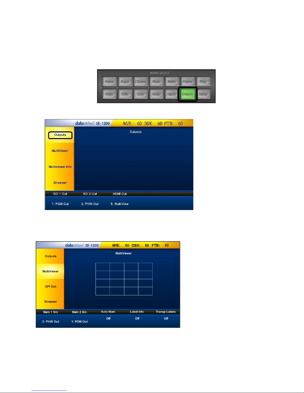
OUTPUTS Key Functions
1. Multiview
2. PGM Out
3. PVW Out
4. PGM DSK1
5. PVW DSK1
6. Clean PGM
7. Clean PVW
8. Input 1
9. Input 2
10. Input 3
11. Input 4
12. Input 5
13. Input 6
1. PGM Out
2. PVW Out
3. PGM DSK1
4. PVW DSK1
5. P-in-P
Setting Video Outputs
1. To assign the output type to the output, click the Outputs button on the MENU SELECT panel.
2. Assign one of the output types listed below to SDI 1 Out, SDI 2 Out and HDMI Out:
Setting MultiViewer
This option allows the user to choose the contents of the Main Screen 1 (Main 1 Src) and Main Screen 2 (Main 2
Src). Click Main 1 Src or Main 2 Src to select the source from the list below:
Other than the main screen settings, the user can also turn ON/OFF Auto Number (Auto Num), Label Information
(Label Info) and Transparent Labels (Transp Labels).
20
 Loading...