

Page 1
HD / SD Digital Video Switcher
SE-1000
Rev 150507
Instruction Manual
http://www.datavideo-tek.com
Page 2

Table of Contents
Warnings and Precautions 4
Warnings and Precautions 4
Radio and Television Interference 4
Warranty 5
Disposal 5
Introduction 6
Introduction 6
Product overview 6
Features 6
Packing List 7
Installation, Connections 8
Power Up State 8
Control Panel 9
Rear Panel 12
Set Up 14
Powering Up 14
Set Up Menus 15
Menu 1/15 Inputs 1 to 5 15
Menu 2/15 DVI Input Mode 16
Menu 3/15 Frame Synchroniser 17
Menu 4/15 Video Format Setting 17
Menu 5/15 Ref Internal / External Sync 18
Menu 6/15 Output Phase Adjustment 19
Menu 7/15 IP Address Settings 21
Menu 8/15 MASK Settings 21
Menu 9/15 GW (GATEWAY) Settings 22
Menu 10/15 Displaying the MAC Address 22
Menu 11/15 BUS Mode Settings A/B P/P 22
Menu 12/15 System Backlight / VANC / BB 0 / 7.5 ire 23
Menu 13/15 DVI Phase / Position Settings 24
Menu 14/15 INIT Initialise SE-1000 24
Menu 15/15 STATS Alarm Info. / Ver No. 25
XPT Menus Setting The Crosspoints 25
Menu 1/3 XPTAS Crosspoint Assignments 25
Menu 2/3 XPTAS Assigning Crosspoints 26
Menu 3/3 XPTAS Crosspoint Switch Timing 26
MEM Menus 27
Menu 1/3 PSMEM Preset Memory 27
Menu 2/3 PSMEM XPT Enable / Disable 28
Menu 3/3 FMEM Frame Memory 28
FRZ Menus Setting Freeze Frames 29
Menu 1/2 FRZ Freeze Frame Assignments 29
Menu 2/2 FRZ Assigning Freeze Frames 29
1
Page 3

CBGD Menus Setting the Background Colour 30
Menu 1/5 CBGD Selecting the Background Colour 30
Menu 2/5 - 5/5 USR1 to USR4 Setting Custom Colours 30
KEY Menus Setting up a Key 31
Menu 1/7 KEY Setting Up A Key 31
Menu 2/7 K-ADJ Key Adjustments 32
Menu 3/7 FILL Key Fill 33
Menu 4/7 - 7/7 USR1 to USR4 Setting Custom Colours 30
EDGE Menus Setting the Key Edge 33
Menu 1/5 EDGE Type Width Colour 33
Menu 2/5 - 5/5 USR1 to USR4 Setting Custom Colours 30
WIPE Menus Setting Wipe Preferences 34
Menu 1/5 BODR (Border) Settings 35
Menu 2/5 - 5/5 USR1 to USR4 Setting Custom Colours 30
TIME Menus Setting Auto Transition Times 35
Menu 1/5 BKGD (Background) Time Setting 35
Menu 2/5 Key Time Setting 36
Format / Standard Converter Set Up 37
Setting the converter output to HD / SD 37
Setting the IRE - NTSC Standard Definition Only 38
Setting the Brightness - Standard Definition Output Only 39
Setting Colour Saturation - Standard Definition Output Only 39
Setting Tint - NTSC Composite Video Output Only 40
Setting an Output to Colour Bar - Standard Definition Output Only 41
Setting an Output to Crosshatch - High Definition Output Only 41
Checking Video In Format 42
Checking Main and Control Firmware Version 42
Resetting a Channel 43
Checking Channel Status 43
Monitoring 44
Basic Operation 45
Switching 45
Performing a Transition Manually (using the T-Bar) 45
Performing a Transition Automatically (Using the Auto Button) 46
Performing a Key 48
Assigning an output to Auxiliary (AUX) 50
Setting an input signal to Freeze Frame 51
Saving an image to flash memory F-MEM 51
Wiring Examples 52
Image Transfer Software 55
PC Requirements 55
Installing the Program 55
Connecting the SE-1000 to a PC 56
Setting the IP Address 56
Setting the Format (Mode) 59
Setting the Aspect Ratio 59
Transferring an image to the SE-1000 60
Transferring an image from the SE-1000 60
2
Page 4

External Interfaces 61
S-422 61
R
PI Connector 62
G
Tally Connector 62
Troubleshooting / FAQ 63
No power 63
No image at output 63
Alarm Lights is On 63
Useful Accessories 64
TLM-433 / TLM-433JF Monitor Bank / Monitor Holder 64
TB-10 Tally Box 64
ITC-100 8 Channel Talkback / Intercom 65
Specifications 66
Service and Support 68
3
Page 5

Warnings and Precautions
1. Read all of these warnings and save them for later reference.
2. Follow all warnings and instructions marked on this unit.
3. Unplug this unit from the wall outlet before cleaning. Do not use liquid or aerosol cleaners. Use a
damp cloth for cleaning.
4. Do not use this unit in or near water. Protect from moisture such as high humidity or rainfall.
5. Do not place this unit on an unstable cart, stand, or table. The unit may fall, causing serious damage.
6. Slots and openings on the cabinet top, back, and bottom are provided for ventilation. To ensure safe
and reliable operation of this unit, and to protect it from overheating, do not block or cover these
penings. Do not place this unit on a bed, sofa, rug, or similar surface, as the ventilation openings on
o
the bottom of the cabinet will be blocked. This unit should never be placed near or over a heat
register or radiator. This unit should not be placed in a built-in installation unless proper ventilation is
provided.
7. This product should only be operated from the type of power source indicated on the marking label
of the AC adapter. If you are not sure of the type of power available, consult your Datavideo dealer
or your local power company.
8. Do not allow anything to rest on the power cord. Do not locate this unit where the power cord will be
walked on, rolled over, or otherwise stressed.
9. If an extension cord must be used with this unit, make sure that the total of the ampere ratings on the
products plugged into the extension cord do not exceed the extension cord’s rating.
10. Make sure that the total amperes of all the units that are plugged into a single wall outlet do not
exceed 15 amperes.
11. Never push objects of any kind into this unit through the cabinet ventilation slots, as they may touch
dangerous voltage points or short out parts that could result in risk of fire or electric shock. Never
spill liquid of any kind onto or into this unit.
12. Except as specifically explained elsewhere in this manual, do not attempt to service this product
yourself. Opening or removing covers that are marked “Do Not Remove” may expose you to
dangerous voltage points or other risks, and will void your warranty. Refer all service issues to
qualified service personnel.
13. Unplug this product from the wall outlet and refer to qualified service personnel under the following
conditions:
a. When the power cord is damaged or frayed;
b. When liquid has spilled into the unit;
c. When the product has been exposed to rain or water;
d. When the product does not operate normally under normal operating conditions. Adjust only
those controls that are covered by the operating instructions in this manual; improper
adjustment of other controls may result in damage to the unit and may often require
extensive work by a qualified technician to restore the unit to normal operation;
e. When the product has been dropped or the cabinet has been damaged;
f. When the product exhibits a distinct change in performance, indicating a need for service.
Radio and Television Interference
UNITED STATES: The equipment described in this manual generates and uses radio frequency energy. If it
is not installed and used in accordance with the instructions in this manual, it may cause interference with
radio and television reception.
This equipment has been tested and found to comply with the limits for a Class B digital device, pursuant to
Part 15 of the FCC Rules. These limits are designed to provide reasonable protection against harmful
interference in a residential installation. This equipment generates, uses, and can radiate radio frequency
energy, and if not installed and used in accordance with these instructions, may cause harmful interference
to radio communications. However, there is no guarantee that interference will not occur in a particular
installation. If this equipment does cause harmful interference to radio or television reception, which can be
determined by turning the equipment off and on, the user is encouraged to try to correct the interference by
one or more of the following measures:
1. Reorient or relocate the receiving antenna;
2. Increase the separation between the equipment and the receiver;
3. Connect the equipment into an outlet on a circuit different from that to which the receiver is
connected.
4
Page 6

If necessary, consult your dealer or an experienced radio/TV technician for help and/or additional
suggestions.
.B.: Changes or modifications not expressly approved by the party responsible for compliance
N
could void the user’s right to operate this equipment.
Peripherals used in conjunction with this equipment must be connected via shielded interface cables. Use of
unshielded interface cables may result in interference to radio and TV reception, and may void the user’s
right to operate this equipment.
Warranty
Datavideo warrants that the equipment it manufactures shall be free from defects in material and
workmanship for a period of 12 months from the date of product purchased. If equipment fails due to such
defects, Datavideo will, at its option, repair or provide a replacement for the defective part or product.
Equipment that fails after the warranty period, has been operated or installed in a manner other than that
specified by Datavideo, or has been subjected to abuse or modification, will be repaired for time and material
charges at the Buyer’s expense. This warranty does not affect your statutory rights within the Country of
purchase.
Disposal
Disposing of this product correctly will help to save valuable resources and prevent any potential negative
effects on human health and the environment which could otherwise arise from inappropriate waste handling.
Penalties may be applicable for incorrect disposal of this waste, in accordance with national legislation.
For EU Customers only - WEEE Marking.
Private Households
This symbol on the product indicates that it will not be treated as household waste. It must
be handed over to the applicable take-back scheme for the recycling of electrical and
electronic equipment. For more detailed information about the recycling of this product,
please contact your local Datavideo office.
For business users in the European Union
If you wish to discard electrical and electronic equipment, please contact your dealer or supplier for further
information.
Information on Disposal in other Countries outside the European Union
This symbol is only valid in the European Union.
If you wish to discard this product, please contact your local authorities or dealer and ask for the correct
method of disposal.
5
Page 7

Introduction
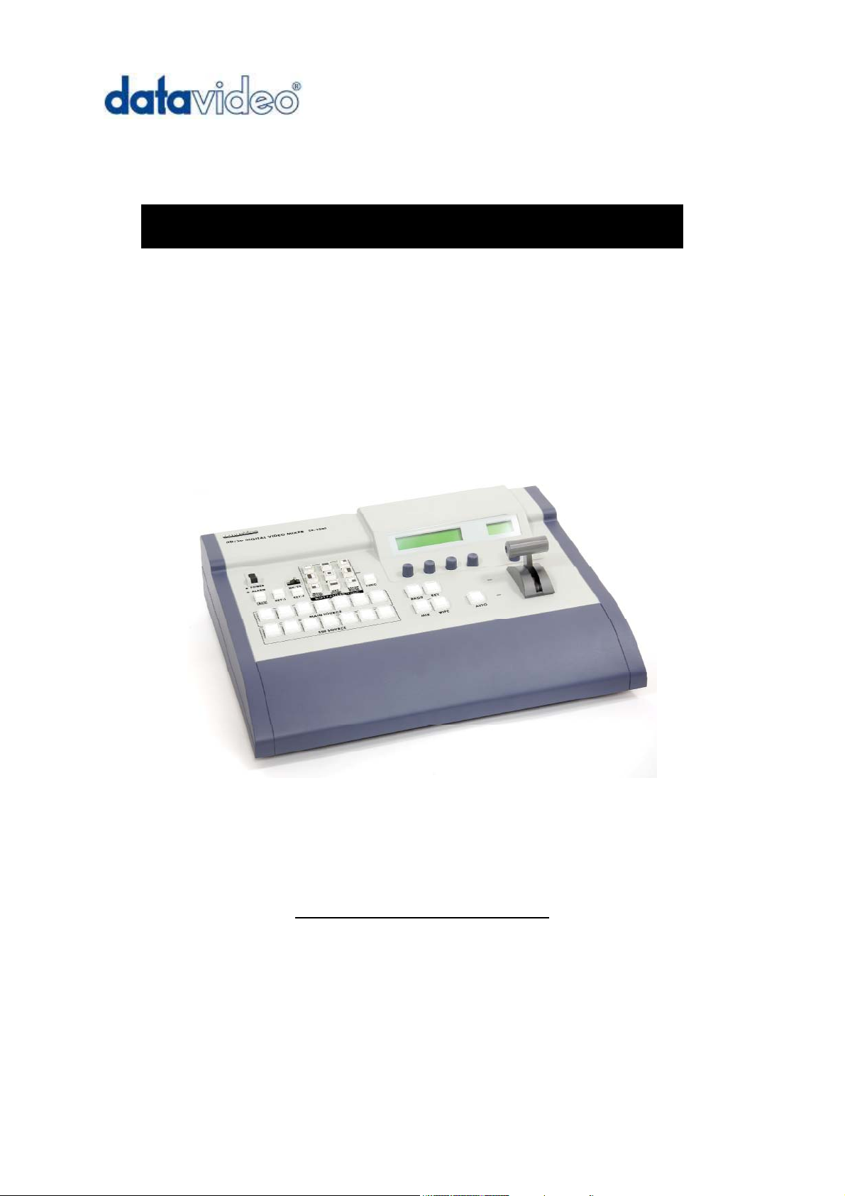
Thank you for purchasing Datavideo’s SE-1000 Digital Video Switcher. We hope you will be pleased with
your purchase, and with what you can achieve with this advanced piece of technology. In order to get the
most out of your new switcher, we recommend that you spend some time getting familiar with this manual, as
it will describe in detail all the functions of this unit. In addition, you’ll find some useful background
information on video and audio, and some detailed examples of ways to use your new switcher.
Product Overview
The Datavideo SE-1000 is an HD / SD input, digital processing live video switcher. The SE-1000 includes 6
groups of video inputs (5 x HD/SD SDI - each with loop through, & 1 x DVI), and 3 x video outputs PGM ( 2 x
HD/SD SDI & 1 x HD/SD Component), PVW (1 x HD/SD SDI & 1 x HD/SD Component) & AUX (2 x HD/SD
SDI & 1 x HD/SD Component). It also incorporates 6 x DAC 40, HD/SD SDI to HD/SD Component /
Composite converters; these allow easy monitoring of inputs and/or outputs. A built in frame synchroniser
ensures glitch free switching of non synchronised inputs. Additional sockets include, Ethernet for image
import from a PC, Tally light output, RS-422 remote control interface, Sync Ref input for external genlock,
and GPI trigger.
Features
Live HD / SD Digital Switcher
Simple Control Panel - The layout of the SE-1000 is extremely simple to follow and ideal for a
live environment.
Six Inputs - five inputs of HD/SD SDI and one DVI
Six HD/SD SDI - HD/SD Component YUV / Composite video converters - These allow SD
monitors to be used for monitoring the input channels, or can be used to convert the HD/SD
Digital SDI outputs to HD/SD Analogue Component YUV.
Multiple Format Support - HD 1080/59.94i, 1080/50i, 720/59.94i, 720/50i / SD 480/59.94i,
576/50i / DVI-I (input only) are the supported formats
Internal or External Sync Support - The SE-1000 has a built in 10-bit frame synchroniser, which
enables clean switching between asynchronous inputs. By using the Black Burst output, systems
can be synchronised to the SE-1000. Alternatively Gen-Lock is possible, by using the Ref In / Out
sockets; the SE-1000 can then be set to external sync (BB or Tri-Level sync).
Built-in Effects and Keying - The SE-1000 has nine different wipe effects, each with a range of
border styles and soft edges. In addition there is a built in Keyer, which offers self or linear keying
as well as key inversion.
Ethernet Capture - Images can be imported from a PC via the Ethernet port, these images can
be used as background images or key input signals
External Control via RS-422 / GPI - The SE-1000 can be controlled from external devices.
Simple control can be gained via GPI, or full control is possible via RS-422.
12v Power Requirement - The SE-1000 can be powered from 12v so it can be easily powered in
the field - Please note Warnings & Precautions on Page 3 in regard to environmental conditions.
Tally output - 6 x Tally light outputs are provided
6
Page 8

Packing List
The SE-1000 is shipped in two versions, if your SE-1000 is in an aluminium carrying case it is version B, if
not it is version A:
Version A
1. SE-1000 switcher x 1
2. BNC to BNC 14.5cm cable x 6
3. YUV Cable - 4 x BNC to BNC Cable 3m x 1
. AC/DC switching adapter 12V 10A x 1
4
5. Power cord x 1
6. Image Transfer Software CD
7. Instruction manual x 1
Version B
1. SE-1000 switcher x 1
2. Aluminium Carrying Case
3. BNC to BNC 14.5cm cable x 6
4. YUV Cable - 4 x BNC to BNC Cable 3m x 1
5. DVI to DVI 1.8m cable x 1
6. RJ45 CAT 5 crossover Ethernet cable 1.8m x 1
7. AC/DC switching adapter 12V 10A x 1
8. Power cord x 1
9. Image Transfer Software CD
10. Instruction manual x 1
7
Page 9

Installation, Connections, Set up
Some General Notes on Installation
There are a few other things to be aware of when you are installing and integrating the SE-1000. Please
make sure you have read the Warnings and Precautions section on page 3.
The SE-1000 sends and receives video signals. You need to be aware that cable lengths, impedance,
rossing power cords, and adaptors might interfere with video transmission, particularly analogue signals.
c
The cautions below, with the exception of physical damage, will give you the general idea about cabling for
video.
We strongly recommend you use video and audio cables that are roughly the right length to connect
between components. The longer the cable, the more noise and deterioration of the video signal can be
introduced. We strongly recommend that you check the integrity of each cable before installation by using a
continuity tester (available from most electronic and video supply stores). Cables can fail over time, with use,
by someone walking on them, carts rolling over them, or even for no apparently good reason. It will happen
eventually. Have a continuity tester handy and save yourself some troubleshooting headaches.
Make sure you don’t run video/audio cables and power lines together, on top of each other, or across each
other. This is another good way to introduce noise and signal degradation.
Cable connectors will eventually become dirty or oxidation will start. The dirt can cause a bad connection or
introduce noise in the signal. It is advisable to buy some electrical contact cleaning products.
Use adaptors if you must, but keep in mind that each connector is one more accident waiting to happen, one
more place the signal can be degraded or broken.
Finally, for examples of how to connect and integrate the SE-1000 into a variety of set ups, take a look at the
brief Quick Start on page 9 and the more in depth explanations in Sample Applications on page 29.
Power up State
When you first power up the SE-1000, you will need to check the settings on each channel. Once set, all the
settings are non-volatile (they will be retained).
On first power up, channel 1 will be the selected Main Video Source (PGM/A) and channel 2 will be the
selected Sub Video Source (PST/B). On all subsequent power ups the video sources will be just as they
were when the unit was switched off.
Settings that are retained are: Video input / output format, DVI mode, format & phase, sync mode (BBST
INT), bus mode (A/B P/P), crosspoint assignment & switching, output signal phase, network settings and all
of the DAC-40 settings.
8
Page 10
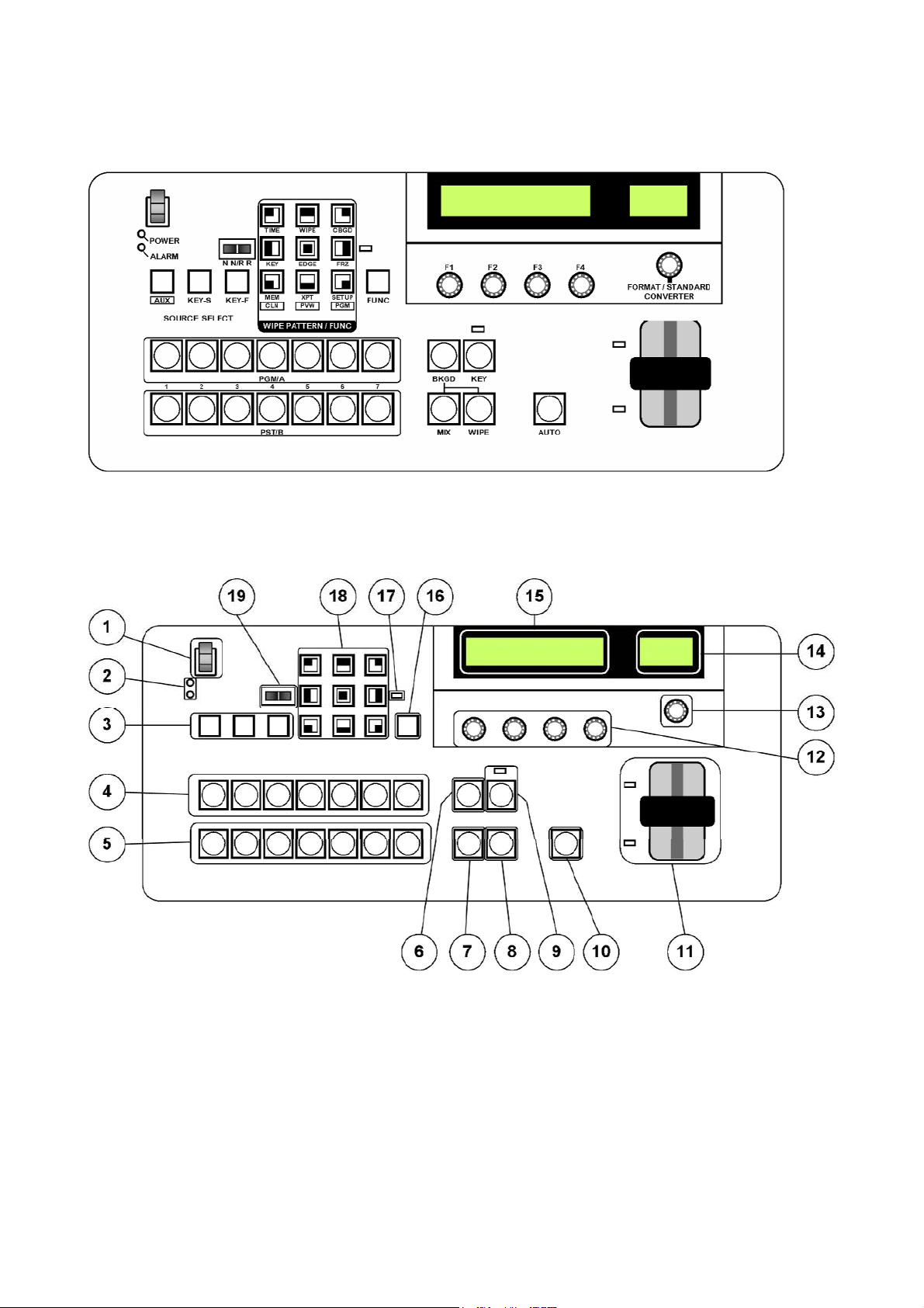
Control Panel
The SE-1000 control panel looks like this:
The layout is clearly labelled, and easy to follow. Many of the buttons have more than one function and are
labelled with different descriptions. For example the nine wipe buttons also have secondary functions when
the [FUNC] button is lit; these secondary functions are printed beneath each key.
Here is a guide to each part of the control panel:
1 Power On/ Off switch. Switched to the “I” position power is on, and in the “O” position power is off.
When power is On the Power Light (2) should light up. You will notice that the power switch has
been designed to prevent the SE-1000 from being accidentally switched off.
2 Power and Alarm LEDs. The Power LED is lit when the SE-1000 is powered on. The Alarm LED will
light up if there is a problem detected, for example if the fan has stopped running or the DC voltage
has dropped. The Status Display in the LCD Panel (15) will indicate the nature of the problem.
N.B. If the alarm LED remains lit please contact your local Datavideo office.
3 Source Selector Buttons - AUX / KEY-S / KEY-F.
When a PST/B bus crosspoint button (5) is pressed while the [AUX] source selector button is held
down, the AUX signals are selected.
9
Page 11

When a PST/B bus crosspoint button (5) is pressed while the [KEY-S] or [KEY-F] source selector
utton is held down, the key signals are selected.
b
While a button is held down, it is illuminated amber.
In addition, if the [CLN], [PVW] or [PGM] wipe pattern selector button (18) is pressed while the [AUX]
button is held down, the button will operate as an AUX bus selector switch.
[CLN]: Clean signals are output to the AUX bus.
[PVW]: PVW signals are output to the AUX bus.
PGM]: PGM signals are output to the AUX bus.
[
4 PGM / A bus crosspoint buttons 1 to 7. These buttons are used to select the PGM / A video source.
If the SE-1000 is set to P/P (PGM/PST) mode, also known as flip-flop mode, then the PGM video
signal is always selected here. If a button is illuminated Red it is Live, if it is illuminated Green it is
Cued
5 PST / B bus crosspoint buttons 1 to 7. These are used to select the PST / B bus video signals. If the
SE-1000 is set to P/P mode (flip-flop), the cued images (PST) are selected here.
When a B bus crosspoint button is pressed while one of the source selector buttons (3) is held down,
KEY signals or AUX signals are selected. If a button is illuminated Red it is Live, if it is illuminated
Green it is Cued
6 BKGD button - Background
This executes the background transition when the [AUTO] button (10) or T Bar (11) has been
operated.
When the [BKGD] button is pressed and it is selected, it is illuminated amber.
If the [KEY] button (9) is now pressed, the indicator goes off, and the de-selected status is
established.
However, when the [BKGD] button and [KEY] button are pressed at the same time, both buttons are
set to the selected status; they are both illuminated amber.
N.B. The selection status cannot be changed while the SE-1000 is in the middle of a transition.
7 MIX button. This is used to select a simple mix or cross dissolve. When the MIX button is active it is
illuminated amber. If the [WIPE] button (8) is selected the Mix button will go out. When the [AUTO]
button (10) or T Bar (11) is operated a cross dissolve will be executed.
8 WIPE button. This is used to select wipe as the transition, whichever wipe button is highlighted in the
wipe pattern selector buttons (18) will become the active transition. When the [AUTO] button (10) or
T Bar (11) is operated a wipe will be executed. If the [MIX] button (7) is selected the WIPE button will
go out.
9 KEY button and LED Indicator. This executes the key transition (MIX) when the [AUTO] button (10)
or T Bar (11) is operated.
When the [KEY] button is pressed and it is selected, it’s illuminated amber.
When a transition is executed and the key ON status is established, the LED above the [KEY] button
is illuminated red. When another transition is executed and the key OFF status is established, it goes
out.
If the [BKGD] button (6) is pressed, the [KEY] button goes out, and the de-selected status is
established.
However, when the [BKGD] button (6) and [KEY] button are pressed at the same time, both buttons
are set to the selected status; both will be amber.
N.B The selection status cannot be changed while the SE-1000 is in the middle of a transition.
10 AUTO button. Automatically executes a transition according to the speed parameters that have been
set. During an auto transition the [AUTO] button is illuminated red. When the transition is complete
the AUTO button goes out. If you press the [AUTO] button during an auto transition the button will
change from red to green, this pauses the transition, pressing the [AUTO] button again will release
the pause and complete the rest of the transition.
If the [AUTO] button is pressed while the T Bar (11) is midway through a transition, then the
transition will be automatically completed at the speed parameter that has been set.
11 T-Bar and LED Bus Indicators. The T Bar is used to carry out a manual transition such as a wipe,
fade, mix or key. When it has travelled as far as it can go the transition is complete.
10
Page 12

The LED indicators alongside the T Bar indicate which bus PGM/A or PST/B is live. The live bus is
ndicated by a green LED. During a transition both LEDs will be green, as both PGM/A and PST/B
i
will be live until the transition is complete.
12 Adjustment Knobs F1 - F4. These are used to set the parameters displayed on the menu.
Menu items are selected and parameters set by rotating [F1] to [F4]. For details on their operation,
refer to the items in Setting Up.
hen the [F1] to [F4] knobs are pushed down, the parameters are returned to their default settings.
W
(Numerical value setting items only).
13 Format Standard Converter Adjustment Knob. This is used to set the parameters for the six built in
standards converters (DAC-40s). Menu items are selected by pushing the knob down, and
parameters are set up rotating the knob. For further details please refer to the item in Setting Up.
14 DAC-40 LCD Display. This LCD displays the settings and parameters for the six built in format
standards converters (DAC-40s). Adjustments are made using the format standard converter
adjustment knob (13). For further details please refer to the item in Setting Up.
15 Main LCD Display. All of the set up menus and parameters are displayed here (except the 6 x DAC-
40 which are displayed on the DAC-40 LCD Display (14). Settings are altered using the adjustment
knobs F1 - F4. For further details please refer to the item in Setting Up.
16 FUNC button - Function. When this button is pressed, it is illuminated green. If a wipe pattern
selector button is pressed while the [FUNC] button is green, the wipe pattern selector button will also
illuminate green, and the setting menu of the function indicated below the button appears on the
LCD display.
[TIME]: For setting the auto transition time.
[WIPE]: For setting the wipe border and soft effect.
[CBGD]: For setting the colour background.
[KEY]: For setting the key.
[EDGE]: For setting the key edge.
[FRZ]: For displaying the freeze status display and setting freeze frames
[MEM]: For setting the preset memory or frame memory.
[XPT]: For displaying and setting the crosspoint assignment.
[SETUP]: For performing the system settings.
17 Freeze Status LED. When this LED is lit it means that one of the input signals is set to freeze frame.
When the [FUNC] button is pressed and it’s illuminated green, and the [FRZ] button is pressed, the
freeze status is indicated for each input. (An asterisk appears above the name of a frozen
crosspoint.)
Bear in mind that since the signals are frozen while the indicator is lit, the unit’s output will remain
unchanged even if the input images change.
Example LCD Display
(When crosspoints 2 and 5 are set to freeze frame)
18 Wipe pattern / function selector buttons. These are used to select the wipe patterns. Each button is
used to select one of the nine wipe patterns. The selected wipe button will be illuminated amber
When the [FUNC] button is active (illuminated green), then the function setting menu is selected, and
the selected wipe button is illuminated green.
19 Wipe direction selector switch. This is used to select the wipe direction. There are three options:
N Sets the wipe pattern to the normal direction
N/R Sets the wipe direction to alternate. When the first transition is completed, the next transition
will run in the opposite direction. For example if you wipe from A to B top to bottom, when
you wipe back from B to A the wipe will automatically be bottom to top.
R Sets the wipe pattern to reverse.
11
Page 13
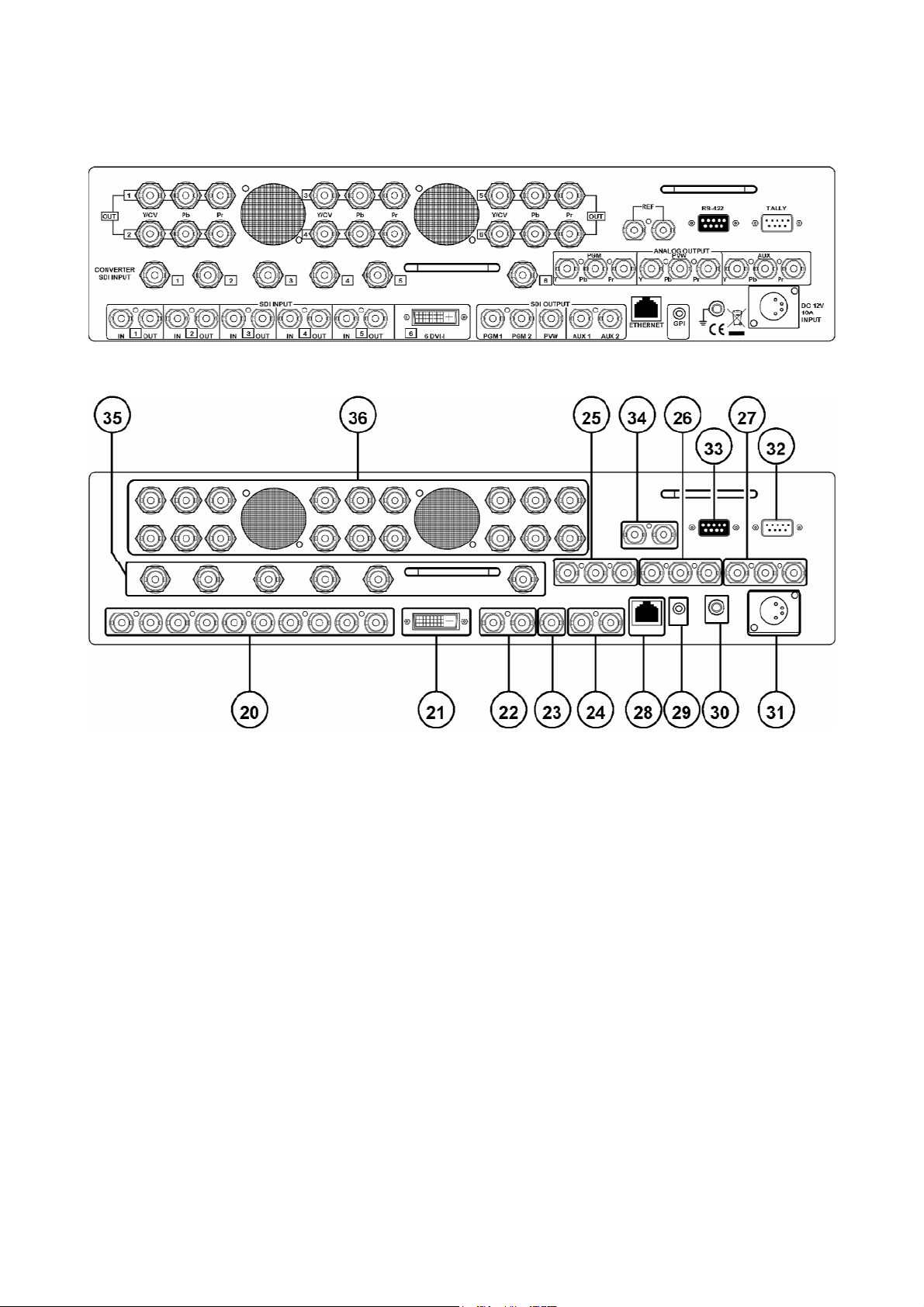
Rear Panel
The rear panel of the SE-1000 looks something like this:
Each section of the panel is clearly labelled, but here is a detailed overview.
20 HD/SD SDI Signal Inputs (Digital Inputs 1 to 5). Each input has a loop through output adjacent to it.
IN = Input OUT = Loop through Output
21 DVI-I Signal Input (Digital Input 6)
22 HD/SD SDI Digital PGM (Program) Output Connecters (PGM 1 & PGM 2)
23 HD/SD SDI Digital PVW (Preview) Output Connecter (PVW)
24 HD/SD SDI Digital AUX (Auxiliary) Output Connecters (AUX 1 & AUX 2)
25 HD/SD YUV Component Analogue PGM (Program) Output Connecters (PGM 1)
26 HD/SD YUV Component Analogue PVW (Preview) Output Connecters (PVW)
27 HD/SD YUV Component Analogue AUX (Auxiliary) Output Connecters (AUX 1)
28 Ethernet 10/100 Port. This is used for importing still images from, and exporting still images to a PC.
29 GPI Port (General Purpose Interface). The GPI port allows simple contact closure control of the
AUTO Take button (10). Each time a contact closure is executed the SE-1000 will automatically
perform the designated transition.
30 Ground / Earth Terminal. When connecting the SE-1000 to any other component, make sure that it is
properly grounded by connecting this terminal to an appropriate point. When connecting, use the
socket and be sure to use wire with a cross-sectional area of at least 1.0 mm2.
12
Page 14

31 DC Power In Socket. Connect the supplied 12V 10A switch mode power supply to this socket.
N.B. If you intend to use an alternative 12v DC supply, ensure that it is within +/- 2V and has a
current of 5 A or more.
32 Tally Out Socket. This supplies tally light information for up to six devices. Please refer to the section
External Interfaces for more details.
33 RS-422 Input Socket. The SE-1000 can be controlled from external devices via the RS-422 socket.
Please refer to the section External Interfaces for more details.
34 External Reference Input and BB Output Connecters (REF). An external sync signal can be fed into
the SE-1000 via the REF In port. The external signal is looped through, so that it may be fed into
other devices.
When the SE-1000 is set to Internal Sync Mode (INT) both REF ports supply BB outputs, so that
other devices can be synced to the SE-1000
35 HD/SD SDI Format/Standard Converter (DAC-40) Inputs (1 to 6). The SE-1000 has six built in
format/standard converters. Each converter can be fed an HD/SD SDI Digital signal, which will then
be converted into an HD/SD YUV or Composite Analogue signal. Please refer to the section Format
Standard Converters in Set Up for more details.
36 Analogue CV / HD/SD YUV Component Format/Standard Converter (DAC-40) Output Connecters.
These are the output connections for the six built in DAC-40 converters. Please refer to the section
Format Standard Converters in Set Up for more details.
13
Page 15
Set Up
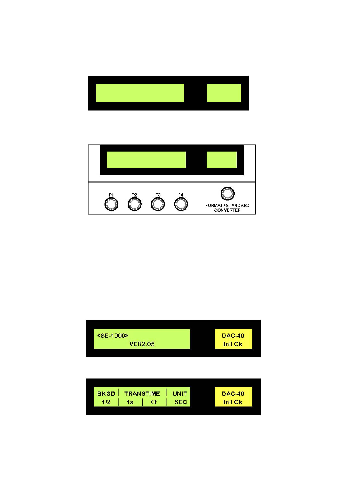
The SE-1000 is set up via various menus, which are displayed on the two LCD panels. The main LCD panel
(15) displays all of the system settings, with the exception of the Format /Standard Converter Settings which
are displayed in the DAC-40 LCD panel (14).
Main LCD Panel DAC-40 LCD Panel
Once accessed each menu is adjusted by using the Adjustment Knobs F1 to F4 (12), or, in the case of the
DAC-40 Format / Standard Converter, by using the Format / Standard Converter Control Knob (13).
Adjustment Knobs F1 to F4 Format / Standard
Converter Adjustment
Knob
We will start by looking at the various menus that are displayed on the main LCD panel.
Powering Up
Using the supplied power cord, connect the 12V 10A power supply to a suitable mains outlet, and then
connect the power supply DC out to the DC IN Socket (31) on the rear of the SE-1000.
Now switch the Power On / Off Switch (1) to the “I” position.
As the SE-1000 boots up the Main LCD panel will briefly show the SE-1000 version number, it is worth
making a note of this.
Once the SE-1000 has finished booting up you will see an information panel displayed on the LCD.
The display may vary but will be similar to the example above. At this stage parameters cannot be changed,
the display is information only.
14
Page 16
Set Up Menus
o view other information and to change parameters we must first press the [FUNC] button. When the
T
[FUNC] button is pressed it will illuminate green, as will one of the Wipe Pattern / Function Selector buttons.
The first time the [FUNC] button is pressed on first boot up, the TIME button will be
illuminated, (this corresponds to the example LCD panel on the previous page). We
ill look at the TIME Menu a bit later, once other settings are complete.
w
First we will look at the SET UP menu options.
Press the [FUNC] button, so that it is illuminated, and then press the [SET UP] button,
so that it is also illuminated.
The buttons, and the LCD panel should look like this:
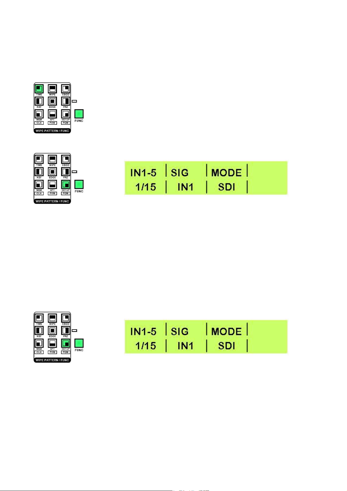
The LCD panel shows information in a uniform fashion.
In the upper left corner is the menu name, which refers to the section that the menu adjusts - In the example
above IN1-5
In the lower left corner is the page number and the total number of pages, for the selected menu - In the
example above 1/15 which means we are on page 1 of the Set Up Menu, and there are a total of 15.
The rest of the display will vary according to the adjustments that can be made in the particular menu.
To navigate the various menu pages rotate Adjustment Knob F1, and to adjust parameters rotate Adjustment
Knobs F2 / F3 / F4 (12).
Set Up Menu 1/15 - Inputs 1 to 5
which refers to Inputs 1 to 5.
This menu is for reference only, as inputs 1 to 5 are automatically SDI.
To leave the menu press the [FUNC] button so that it is no longer illuminated.
15
Page 17
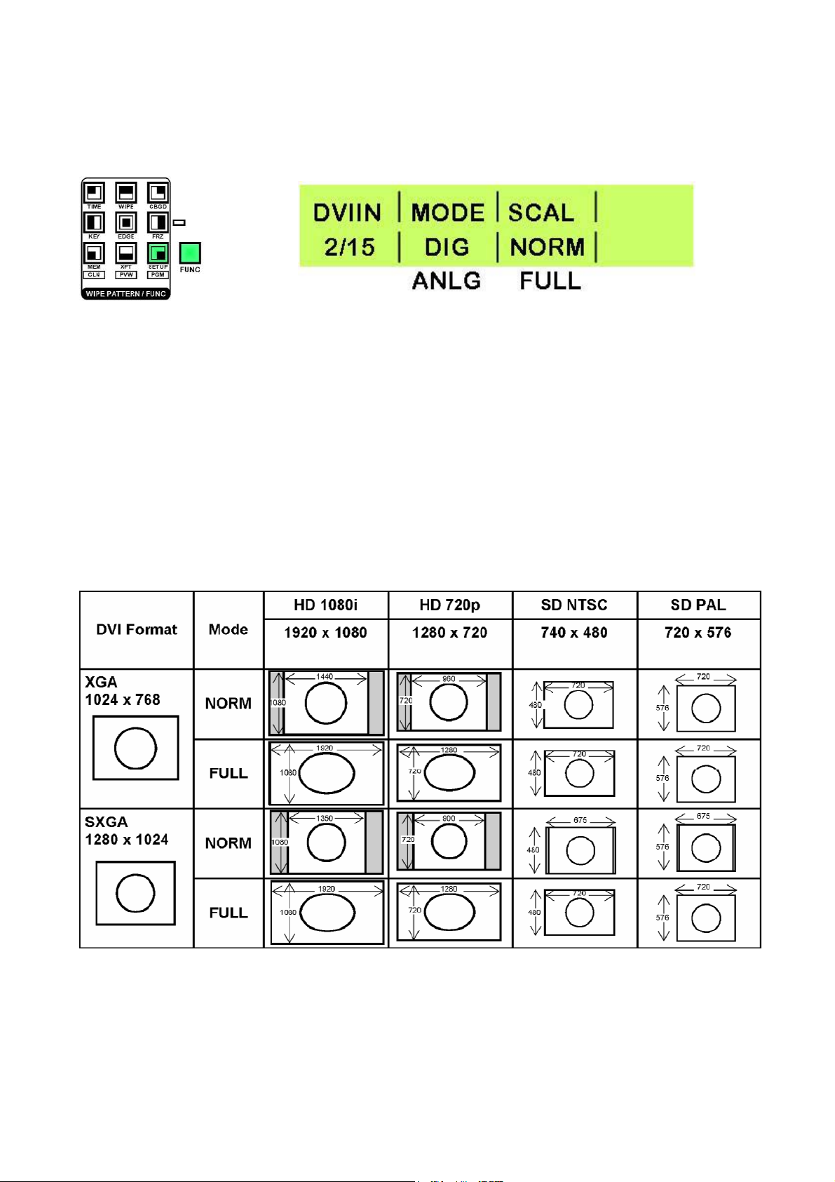
Set Up Menu 2/15 - DVI Input Mode
Press the [FUNC] button, so that it is illuminated, and then press the [SET UP] button, so that it is also
illuminated.
Rotate Adjustment Knob F1 until DVIIN 2/15 is displayed
The recommended screen resolutions for the DVI input are 1024 x 768 (XGA) and 1280 x 1024 (SXGA).
The DVI input can be set to digital or analogue according to the type of signal you want to use.
Use Adjustment Knob F2 to change the setting.
You can set the scaling of the DVI image to normal (NORM) or full (FULL) by rotating Adjustment Knob F3,
please see the following table.
NORM - Fills the screen vertically but maintains the aspect ratio of the original format.
FULL - Stretches the image to fill the screen horizontally and vertically.
N.B. Please also read Set Up Menu 13/15 DVI Phase / Position Settings (Page 23).
To leave the menu press the [FUNC] button so that it is no longer illuminated.
DVI Format Reference Table:
16
Page 18
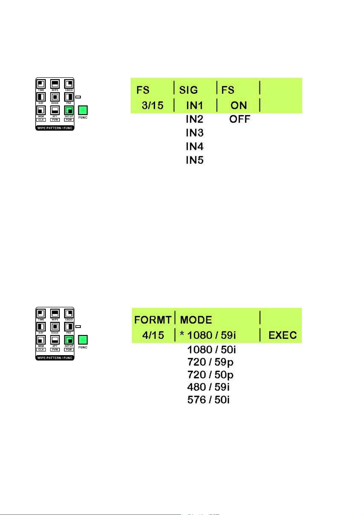
Set Up Menu 3/15 - Frame Synchroniser
Press the [FUNC] button, so that it is illuminated, and then press the [SET UP] button, so that it is also
illuminated.
Rotate Adjustment Knob F1 until FS 3/15 is displayed
By default all inputs of the SE-1000 are set with the frame synchroniser on.
With Inputs 1 to 5 you can switch the frame synchroniser on or off; the frame synchroniser on input 6 (DVI) is
always on.
Use Adjustment Knob F2 to select the input, and Adjustment Knob F3 to set On or Off.
To leave the menu press the [FUNC] button so that it is no longer illuminated.
If you choose to set the frame synchroniser to off, the SE-1000 uses an automatic signal phase adjustment
(AVDL) which will adjust the input signal phase to the horizontal synchronisation reference signal phase.
Please also refer to Menu 6/15 Output Phase Adjustment.
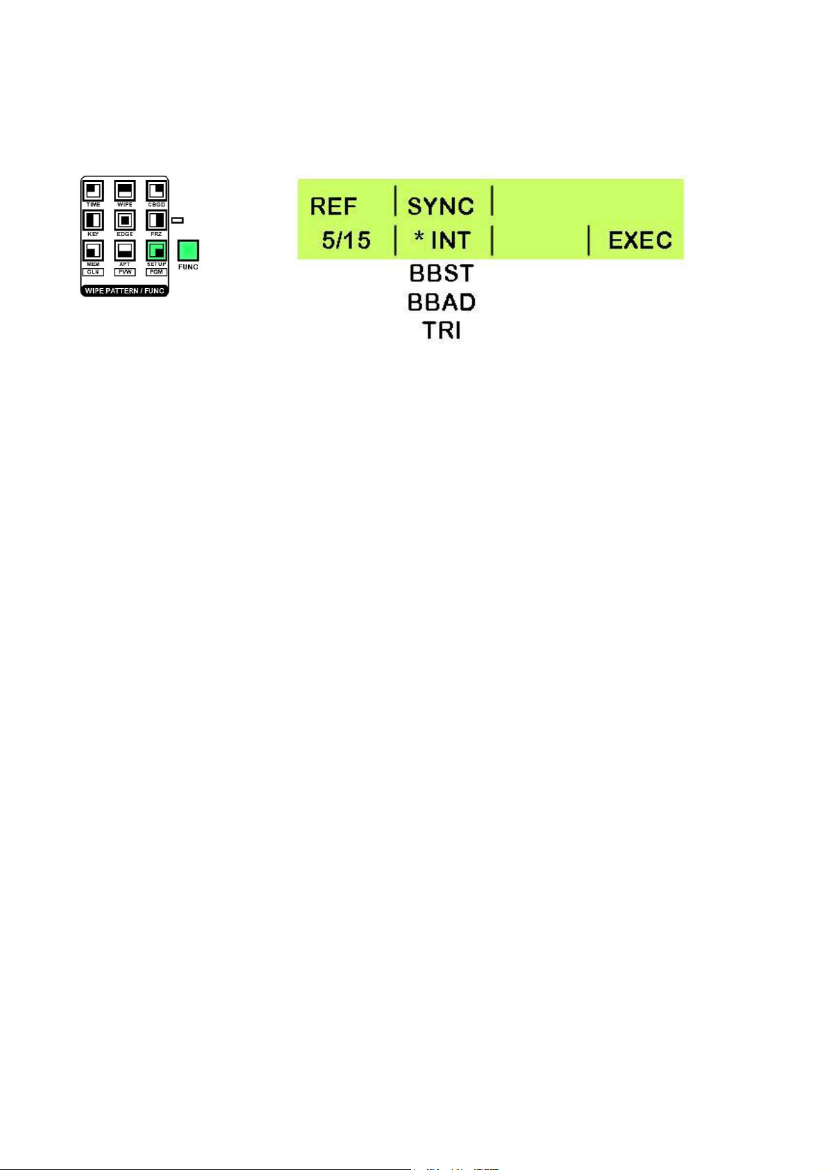
Set Up Menu 4/15 - Video Format Setting
Press the [FUNC] button, so that it is illuminated, and then press the [SET UP] button, so that it is also
illuminated.
Rotate Adjustment Knob F1 until FORMT 4/15 is displayed
The SE-1000 can only be set to one format. It is not possible to combine SD and HD signals on different
inputs. The format mode selected must match the format of the inputs being used.
To set the format, rotate Adjustment Knob F2 until the format you require is being displayed, then press
Adjustment Knob F4 to confirm the setting.
The active format will be marked with an * ; in the example above 1080 / 59i is the active format.
To leave the menu press the [FUNC] button so that it is no longer illuminated.
17
Page 19
Set Up Menu - 5/15 Ref - Internal External Sync.
Press the [FUNC] button, so that it is illuminated, and then press the [SET UP] button, so that it is also
illuminated.
Rotate Adjustment Knob F1 until REF 5/15 is displayed.
The SE-1000 can be set to either internal or external synchronisation.
If the SE-1000 is set to internal synchronisation it can cleanly switch asynchronous video inputs.
In any of the external synchronisation modes a reference signal will be required.
There are three external modes available:
BBST - Black Burst Signal (vertical phase of 0H)
BBAD - Black Burst Signal (vertical phase of 90H for 59.94i / p formats, or 75H for 50i / p formats)
(Available in HD Formats only)
TRI - Tri-Level Sync Signal (vertical phase of 0H)
(Available in HD Formats only)
To change the sync mode rotate Adjustment Knob F2 until the required setting is displayed, and then press
Adjustment Knob F4 to confirm the setting.
The active format will be marked with an *; in the example above INT is the active format.
To leave the menu press the [FUNC] button so that it is no longer illuminated.
18
Page 20
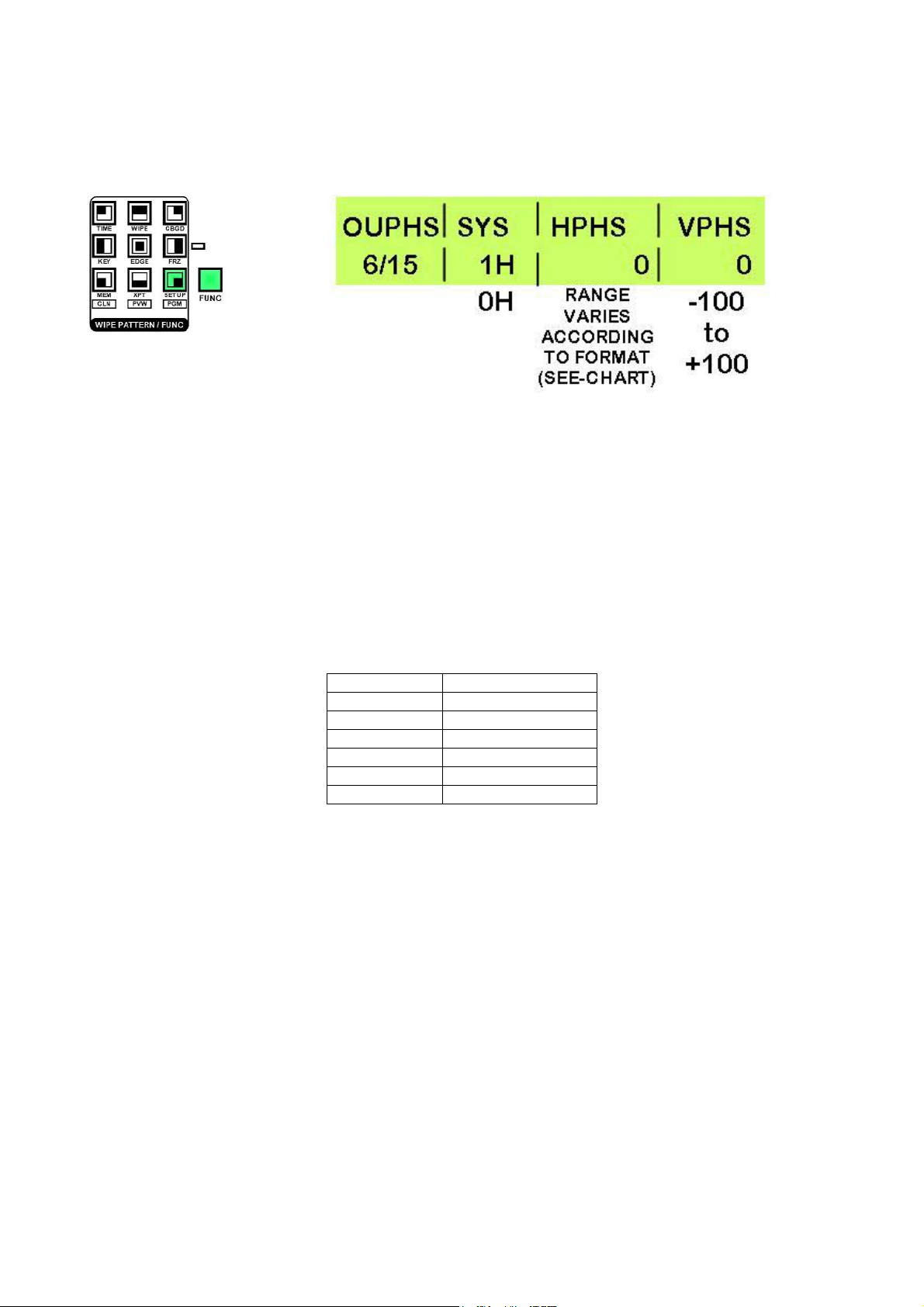
Menu 6/15 Output Phase Adjustment
Press the [FUNC] button, so that it is illuminated, and then press the [SET UP] button, so that it is also
illuminated.
Rotate Adjustment Knob F1 until OUPHS 6/15 is displayed.
The phase of the video output signals can be adjusted as follows:
By rotating Adjustment Knob F2 you can choose between 0H or 1H:
0H - The output video signals are output to the system REF signal output in-phase.
In this mode the frame synchroniser should be ON for all inputs.
1H - The output video signals are output to the system REF signal output with 1H delay.
You can adjust Horizontal Phase (HPHS) by rotating Adjustment Knob F3, the range varies according the
system format that you selected - see chart.
Video Format
1080 / 59i -1100 to 1099
1080 / 50i -1320 to 1319
720 / 59i -825 to 824
720 / 50p -990 to 989
480 / 59i -429 to 428
576 / 50i -432 to 431
Adjustment Range
Vertical Phase (VPHS) can be adjusted by rotating Adjustment Knob F4.
To leave the menu press the [FUNC] button so that it is no longer illuminated.
19
Page 21
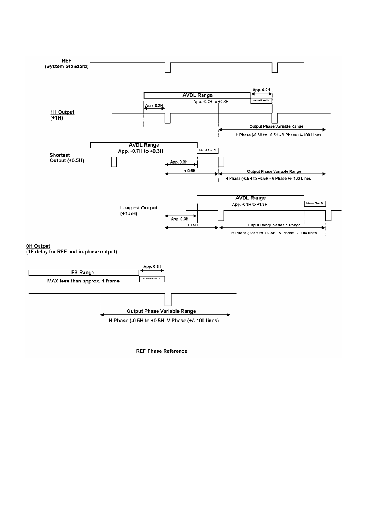
Phase Adjustment Set Up Diagram:
20
Page 22

Menu 7/15 IP Address Settings
Press the [FUNC] button, so that it is illuminated, and then press the [SET UP] button, so that it is also
illuminated.
Rotate Adjustment Knob F1 until IP 7/15 is displayed.
The default IP Address is 192.168.0.10.
This can be adjusted if required.
Rotate Adjustment Knob F2, you will see the * move across the line from left to right. Position the * above the
parameter that you want to change; in the example above 192.
Rotate Adjustment Knob F3 to change the value. As you change the value you will see a ! appear next to the
*, this indicates that the value has been changed but not stored.
Once you have set the required value press Adjustment Knob F3 - you will see the ! disappear, which
confirms the new value is stored.
To leave the menu press the [FUNC] button so that it is no longer illuminated.
Menu 8/15 MASK Settings
Press the [FUNC] button, so that it is illuminated, and then press the [SET UP] button, so that it is also
illuminated.
Rotate Adjustment Knob F1 until MASK 8/15 is displayed.
The default MASK is 255.255.255.0.
This can be adjusted if required.
Rotate Adjustment Knob F2, you will see the * move across the line from left to right. Position the * above the
parameter that you want to change; in the example above the first 255.
Rotate Adjustment Knob F3 to change the value. As you change the value you will see a ! appear next to the
*, this indicates that the value has been changed but not stored.
Once you have set the required value press Adjustment Knob F3 - you will see the ! disappear, which
confirms the new value is stored.
To leave the menu press the [FUNC] button so that it is no longer illuminated.
21
Page 23

Menu 9/15 GW (Gateway) Settings
Press the [FUNC] button, so that it is illuminated, and then press the [SET UP] button, so that it is also
illuminated.
Rotate Adjustment Knob F1 until GW 9/15 is displayed.
The default Gateway is 0.0.0.0.
This can be adjusted if required.
Rotate Adjustment Knob F2, you will see the * move across the line from left to right. Position the * above the
parameter that you want to change; in the example above the first 0.
Rotate Adjustment Knob F3 to change the value. As you change the value you will see a ! appear next to the
*, this indicates that the value has been changed but not stored.
Once you have set the required value press Adjustment Knob F3 - you will see the ! disappear, which
confirms the new value is stored.
To leave the menu press the [FUNC] button so that it is no longer illuminated.
Menu 10/15 Displaying the MAC Address
Press the [FUNC] button, so that it is illuminated, and then press the [SET UP] button, so that it is also
illuminated.
Rotate Adjustment Knob F1 until MAC 10/15 is displayed.
The MAC Address will be displayed, on this case 00073601000
To leave the menu press the [FUNC] button so that it is no longer illuminated.
Menu 11/15 Bus Mode Settings
The SE-1000 has two different bus modes, these affect the way the PGM/A and PST/B crosspoint buttons
work.
In A / B Mode the live output switches between crosspoint rail A (PGM) and crosspoint rail B (PST). Each
time a transition or switch is performed the output will switch from A to B or B to A.
Example:
Before Transition- B is RED During Transition A / B are RED After Transition A is RED
22
Page 24

n P/P Mode (PGM / PST), often referred to as flip flop mode, the output will always be from the PGM/A
I
crosspoint rail, and PST/B will always be the cued channel.
Example:
Before Transition A is RED During Transition A / B are RED After Transition A is RED
To change the Bus Mode:
Press the [FUNC] button, so that it is illuminated, and then press the [SET UP] button, so that it is also
illuminated.
Rotate Adjustment Knob F1 until BUS 11/15 is displayed.
Rotate to Adjustment Knob F2 to switch between modes.
To leave the menu press the [FUNC] button so that it is no longer illuminated.
Menu 12/15 System Settings for LCDBacklight / VANC / BB 0 / 7.5 ire
The SYS (System) menu contains three settings, Backlight On/Off, VANC On/Off and BB.
Press the [FUNC] button, so that it is illuminated, and then press the [SET UP] button, so that it is also
illuminated.
Rotate Adjustment Knob F1 until SYS 12/15 is displayed.
Rotate Adjustment Knob F2 to turn the LCD Backlight On / Off.
Rotate Adjustment Knob F3 to turn VANC On / Off - On VANC Data is passed through / Off VANC data is not
passed through.
Rotate Adjustment knob F4 to change the BB ire setting from 0 to 7.5. This only applies to 59i / 59Pformats;
50i and 50p will always default to 0 ire.
As a general rule North American NTSC equipment uses 7.5 ire, Japanese NTSC equipment uses 0 ire.
To leave the menu press the [FUNC] button so that it is no longer illuminated.
23
Page 25

Menu 13/15 DVI Phase / Position Settings
Press the [FUNC] button, so that it is illuminated, and then press the [SET UP] button, so that it is also
illuminated.
Rotate Adjustment Knob F1 until DVIPH 13/15 is displayed.
Rotate Adjustment Knob F2 to adjust the clock/phase of the analogue DVI input, try to minimise any noise in
the image.
Rotate Adjustment Knob F3 to alter the horizontal position (HPOS) of the DVI input.
Rotate Adjustment Knob F4 to alter the vertical position (VPOS) of the DVI input.
To leave the menu press the [FUNC] button so that it is no longer illuminated.
Menu 14/15 INIT Initialise SE-1000
Init will return the SE-1000 to its factory default settings.
Press the [FUNC] button, so that it is illuminated, and then press the [SET UP] button, so that it is also
illuminated.
Rotate Adjustment Knob F1 until INIT 14/15 is displayed.
To reset the SE-1000 to factory default:
Press Adjustment Knob F2.
If you are certain that you want to continue, rotate Adjustment Knob F2 so that No changes to Yes, then
press Adjustment Knob F2 to confirm.
The SE-1000 will reset itself to default settings.
24
Page 26

Menu 15/15 STATS Alarm Info. / Ver No.
The STATS display gives information about alarm events and SE-1000 firmware version number; there are
no adjustments to be made.
Press the [FUNC] button, so that it is illuminated, and then press the [SET UP] button, so that it is also
illuminated.
Rotate Adjustment Knob F1 until STATS 15/15 is displayed.
ALM If the alarm LED has illuminated on the SE-1000, you should check this menu to see the cause, this
could be the fan, a power fluctuation or both fan and power (F P).
OPT (is not used on this model)
VER displays the version number, which you will be required to know if you contact technical support.
To leave the menu press the [FUNC] button so that it is no longer illuminated.
XPT Menus Setting The Crosspoints
Crosspoint assignments determine which signal is routed to which button. The settings that you can see
below are the default settings. You can choose to route the signals in whatever way you like.
Menu 1/3 XPTAS Crosspoint Assignments
The XPTAS display gives information about crosspoint assignments; there are no adjustments to be made.
To make adjustments you need to go into XPTAS Menu 2/3.
Press the [FUNC] button, so that it is illuminated, and then press the [XPT] button, so that it is also
illuminated.
Rotate Adjustment Knob F1 until XPTAS 1/3 is displayed.
The display indicates that:
1 is set to black
2 is set to input 1
3 is set to input 2
4 is set to input 3
5 is set to input 4
6 is set to input 5
7 is set to DVI (input 6)
Other options that may be displayed are:
G - Colour Background
C - Colour Bars
F - FMEM
To leave the menu press the [FUNC] button so that it is no longer illuminated.
25
Page 27

Menu 2/3 XPTAS Assigning Crosspoints
Press the [FUNC] button, so that it is illuminated, and then press the [XPT] button, so that it is also
illuminated.
Rotate Adjustment Knob F1 until XPTAS 2/3 is displayed.
Rotate Adjustment Knob F2 to select the crosspoint (XPT) that you want to change.
Rotate Adjustment Knob F3 to select the signal (SIG) that you want to assign.
The signal options are:
IN1 to IN5 SD/HD SDI Video Inputs 1 to 5
DVI DVI Input (Video Input 6)
BLK Black (Internally generated)
CBGD Colour Background (Internally generated)
CBAR Colour Bar (Test Pattern) (Internally Generated)
FMEM Frame Memory Image
(see MEM Menus - FMEM 3/3 Frame Memory - Page 27)
To leave the menu press the [FUNC] button so that it is no longer illuminated.
Menu 3/3 XPTAS Crosspoint Switch Timing
Press the [FUNC] button, so that it is illuminated, and then press the [XPT] button, so that it is also
illuminated.
Rotate Adjustment Knob F1 until XPTAS 3/3 is displayed.
Rotate Adjustment Knob F2 to change the switch timing setting (TIMG). ANY is ok for live applications; F1
and F2 are suited to NLE applications. F1 switches on field1 and F2 switches on field 2, some NLE systems
favour 1 and some favour 2, if in doubt consult you NLE application provider.
To leave the menu press the [FUNC] button so that it is no longer illuminated.
26
Page 28

MEM Menus
The SE-1000 can store up to 10 panel settings in the preset memory. The preset memory is flash memory,
so it is stored even when the SE-1000 is switched off, or initialised (INIT).
The following settings can be stored:
Item Description Default Value
ROSSPOINT
C
WIPE
TRANSITION AREA
KEY
USER COLOUR
Bus 1
A
B Bus 1
Key S 1
Key F 1
AUX Bus 1
Colour Background WHITE
Wipe Pattern 4 (Centre)
Border Width 50
Soft Edge Width 4
Border Colour YLW (Yellow)
BKGD / KEY Selection BKGD
MIX / WIPE Selection MIX
Auto Transition Time (BKGD) 30 F (Frames)
Auto Transition Time (KEY) 30 F (Frames)
Key Type (TYPE) LIN
Key Adjustment (ADJ) GAIN: 100
CLIP: 0
DENS: 100
Inversion ON / OFF OFF
Fill Colour BLE (Blue)
Edge Colour YLW (Yellow)
Edge ON / OFF (TYPE) OFF
Edge Width 4
User Colour 1 (HUE / SAT / LUM) 0 , 0 , 100
User Colour 2 (HUE / SAT / LUM) 355 , 100 , 7
User Colour 3 (HUE / SAT / LUM) 50 , 100 , 9
User Colour 4 (HUE / SAT / LUM) 0 , 0 , 0
Menu 1/3 PSMEM Preset Memory
PSMEM 1/3 allows you to store, recall and clear presets.
Press the [FUNC] button, so that it is illuminated, and then press the [MEM] button, so that it is also
illuminated.
Rotate Adjustment Knob F1 until PSMEM 1/3 is displayed.
Rotate Adjustment Knob F2 to select the mode you require:
STOR - To store values to a preset
RECL - To recall values from a preset and change the panel settings
CLR - To clear values from a preset
27
Page 29

Rotate Adjustment Knob F3 to select the number (NO.) of the preset that you wish to use (1 to 10). If any
information is stored on a preset you will see an * next to the number. (In the example above *1 has stored
information)
To execute the command (STOR / RECL / CLR) press Adjustment Knob F4; after a few seconds the action
is complete.
To leave the menu press the [FUNC] button so that it is no longer illuminated.
Menu 2/3 PSMEM XPT Enable / Disable
PSMEM 2/3 allows you to enable or disable the crosspoint setting presets. If XPT is enabled then the XPT
settings will be overwritten when a preset memory is recalled, if XPT is disabled the crosspoint settings will
remain as they are, even when a preset memory is recalled.
For example if you have selected 1 on the PGM/A Rail and 2 on the PST/B Rail, when disable is selected
(DSBL) these settings will not change when you recall any preset memory. If enable (ENBL) is selected the
selections on the PGM/A and PST/B rails will change when a preset memory is recalled.
Press the [FUNC] button, so that it is illuminated, and then press the [MEM] button, so that it is also
illuminated.
Rotate Adjustment Knob F1 until PSMEM 2/3 is displayed.
Rotate Adjustment Knob F2 to select ENBL (enable) or DSBL (disable).
To leave the menu press the [FUNC] button so that it is no longer illuminated.
Menu 3/3 FMEM Frame Memory
FMEM allows you to store a still image from the AUX output signal; this image can then be assigned to a
crosspoint.
N.B. The frame store is 8-bit, so the stored image may appear slightly downgraded.
Press the [FUNC] button, so that it is illuminated, and then press the [MEM] button, so that it is also
illuminated.
Rotate Adjustment Knob F1 until FMEM 3/3 is displayed.
Watch the AUX output signal, and when you see the image you want to store press Adjustment Knob F4.
To assign the stored FMEM image to a crosspoint see Menu 2/3 XPTAS Assigning Crosspoints - Page 25
To leave the menu press the [FUNC] button so that it is no longer illuminated.
Frames can also be stored to FMEM from a PC via Ethernet, see Image Transfer Software.
28
Page 30

FRZ Menus Setting Freeze Frames
Each of the video inputs on the SE-1000 can be set to freeze frame at any time. The freeze frame will be
held as a still image.
Menu 1/2 FRZ Freeze Frame Assignments
The FRZ 1/2 display gives information about which crosspoints have freeze frames assigned. An * above the
crosspoint number indicates that a freeze frame is assigned. In the example below crosspoints 2 and 5 are
both assigned a freeze frame.
Press the [FUNC] button, so that it is illuminated, and then press the [FRZ] button, so that it is also
illuminated.
Rotate Adjustment Knob F1 until FRZ 1/2 is displayed.
To leave the menu press the [FUNC] button so that it is no longer illuminated.
Menu 2/2 FRZ Assigning Freeze Frames
To assign freeze frames:
Press the [FUNC] button, so that it is illuminated, and then press the [FRZ] button, so that it is also
illuminated.
Rotate Adjustment Knob F1 until FRZ 2/2 is displayed.
Rotate Adjustment Knob F2 to select the input (SIG) that you want to freeze.
Watch the video input on a monitor and when you see the image you want to freeze, press Adjustment Knob
F4 - The LCD display will change from OFF to ON.
To release the input from the freeze frame press Adjustment Knob F4 - The LCD display will change from
ON to OFF.
To leave the menu press the [FUNC] button so that it is no longer illuminated.
N.B. If any inputs are set to freeze frame the Freeze Status LED will light up.
29
Page 31

CBGD Menus Setting the Background Colour
Menu 1/5 CBGD - Colour Background
The CBGD Menu 1/5 allows you to set the colour of the background
CBGD Menus 2/5 to 5/5 allow you to set four custom colours - USR1 to USR4 - these can be used in the
EDGE, KEY, CBGD and WIPE Settings.
Press the [FUNC] button, so that it is illuminated, and then press the [CBGD] button, so that it is also
illuminated.
Rotate Adjustment Knob F1 until CBGD 1/5 is displayed.
Rotate Adjustment Knob F2 to select the colour you require. There are eight preset colours available, plus
four custom colours (USR1 to USR4) (see USR1 to USR4 Setting Custom Colours).
To leave the menu press the [FUNC] button so that it is no longer illuminated.
Menus 2/5 to 5/5 USR1 to USR4 Setting Custom Colours
The following settings apply to:
CBGD Menus 2/5 to 5/5
EDGE Menus 2/5 to 5/5
KEY Menus 4/7 to 7/7
WIPE Menus 2/5 to 5/5
USR-1 to USR-4 allow you to set custom colours which can be used in the same way as the eight preset
colours. Once set, the custom colours are stored even when the unit is switched off.
Adjusting any one of the menus will change the settings in all of the menus; e.g. USR1 in EDGE, KEY,
CBGD & WIPE is the same setting.
In order to see what you are adjusting you will firstly need to assign CBGD to a crosspoint (see XPTAS
Assigning Crosspoints - page 25). Select the crosspoint that has been assigned as CBGD as the Program
(PGM) Output, you should see a solid background colour on your output monitor.
30
Page 32

You will also need to set the CBGD to the USR number that you are adjusting. E.g. If you are adjusting
SR1 you need to set the CBGD Colour to USR1 in order to see the colour background that you are
U
adjusting on your output monitor.
To set USR1, USR2, USR3 & USR4 follow this procedure. In this example we are using the CBGD Menu,
but the procedure would be similar if you were using the EDGE, KEY, or WIPE menus.
ress the [FUNC] button, so that it is illuminated, and then press the [CBGD] button, so that it is also
P
illuminated.
Rotate Adjustment Knob F1 until USR1 2/5 is displayed.
Rotate Adjustment Knob F2 to alter the hue of the custom colour. 0 is the red end of the spectrum and as
you increase the hue value you will see the colour change gradually through blues, greens, yellows and
finally back to reds.
N.B. if saturation (SAT) or Luminance (LUM) is set to 0 you will not see any colour changes.
Rotate Adjustment Knob F3 to alter the colour saturation of the custom colour. 0 is monochrome (black and
white) and 100 is full primary colour.
Rotate Adjustment Knob F4 to alter the luminance (brightness) of the custom colour. 0 is black and 100 is
white (with colour saturation (SAT) set to 0)
Repeat the above settings for USR2, USR3 & USR4; rotate Adjustment Knob F1 to select between USR1,
USR2, USR3 & USR4.
Once you have set the custom colours, to leave the menu press the [FUNC] button so that it is no longer
illuminated.
KEY Menus Setting up a Key
Keying allows you to use an image, ideally black and white, to combine two images. The black element of
the key image will be replaced by the background image, and the white element will be replaced by the key
fill.
31
Page 33

Menu 1/7 KEY Setting Up A Key
ress the [FUNC] button, so that it is illuminated, and then press the [KEY] button, so that it is also
P
illuminated.
Rotate Adjustment Knob F1 until KEY 1/7 is displayed.
Rotate Adjustment Knob F2 to select between LIN (Linear) or SELF keying.
LIN Linear uses the luminance signals of the selected Key Source.
SELF Self uses the luminance signals of the key fill. As the luminance signals of the key fill are being used
the key source is effectively irrelevant.
Rotate Adjustment Knob F3 to switch INV (Invert) On or Off. Invert reverses the key effect, i.e. the white area
will be replaced by the background image and the black area will become the key fill.
Rotate Adjustment Knob F3 to select the PVW (PREVIEW) Mode.
AUTO Preview images of the next transition are output to preview
ON Images with Key Effects added are output to preview
OFF Images are output to preview without Key Effects added.
To leave the menu press the [FUNC] button so that it is no longer illuminated.
Menu 2/7 K-ADJ Key Adjustments
Key adjustments fine tune the way the key is going to appear. It is easiest to adjust these settings with the
key output shown on the preview or program monitor.
Press the [FUNC] button, so that it is illuminated, and then press the [KEY] button, so that it is also
illuminated.
Rotate Adjustment Knob F1 until K-ADJ 2/7 is displayed.
Rotate Adjustment Knob F2 to alter the CLIP setting. This will increase the reference level for creating the
key. Default value is 0
Rotate Adjustment Knob F3 to alter the GAIN setting. This will increase / decrease the key gain. Default
value is 100
Rotate Adjustment Knob F4 to alter the DENS (Density) setting. This will increase / decrease the key density.
Default value is 100
To leave the menu press the [FUNC] button so that it is no longer illuminated.
32
Page 34

Menu 3/7 Fill Key Fill
Press the [FUNC] button, so that it is illuminated, and then press the [KEY] button, so that it is also
illuminated.
Rotate Adjustment Knob F1 until FILL 3/7 is displayed.
Rotate Adjustment Knob F2 to select between BUS or COLR
BUS Will use the selected Key Fill video signal
COLR Will use the selected colour as the Key Fill
Rotate Adjustment Knob F3 to select the colour for the Key Fill. You can choose from one of the eight preset
colours, or one of the four user defined custom colours.
To leave the menu press the [FUNC] button so that it is no longer illuminated.
Menu 4/7 - 7/7 USR1 to USR4 Setting Custom Colours
These settings are covered in CBGD Menus - Menus 2/5 to 5/5 USR1 to USR4 Setting Custom Colours see page 30
EDGE Menus Setting the Key Edge
The EDGE Menu 1/5 allows you to set the edge style for Keying Effects. The settings include Edge Type,
Width and Colour.
EDGE Menus 2/5 to 5/5 allow you to set four custom colours - USR1 to USR4 - these are the same settings
that are used in KEY, CBGD and WIPE BODR Settings.
Menu 1/5 EDGE Type Width Colour
The EDGE Menu 1/5 allows you to set the edge style for Keying Effects. The settings include Edge Type,
Width and Colour.
33
Page 35

DGE Menus 2/5 to 5/5 allow you to set four custom colours - USR1 to USR4 - these are the same settings
E
that are used in KEY, CBGD and WIPE BODR Settings.
Press the [FUNC] button, so that it is illuminated, and then press the [EDGE] button, so that it is also
illuminated.
Rotate Adjustment Knob F1 until EDGE 1/5 is displayed.
Rotate Adjustment Knob F2 to select the type of edge you require.
OFF - No edge will be added.
BODR - A border is added around the entire edge of the key object.
DROP - A border is added to the bottom right hand side of the key object.
SHDW - A shadow is added to the bottom right hand side of the key object.
OUTL - An outline, just a border with no fill, is added around the entire key object
Rotate Adjustment Knob F3 to select the width of the edge that you require.
Rotate Adjustment Knob F4 to select the colour of the edge that you require. There are eight preset colours
available, plus four custom colours (USR1 to USR4) (see USR1 to USR4 Setting Custom Colours)
To leave the menu press the [FUNC] button so that it is no longer illuminated.
Menu 2/5 - 5/5 USR1 to USR4 Setting Custom Colours
These settings are covered in CBGD Menus - Menus 2/5 to 5/5 USR1 to USR4 Setting Custom Colours see page 30
WIPE Menus Setting Wipe Preferences
Menu 1/5 allows you to select the width, softness and colour of your wipe borders.
Menus 2/5 - 5/5 allow you to define the four custom colours USR1 - USR4 - these are the same settings that
are used in EDGE, KEY and CBGD Settings.
34
Page 36

Menu 1/5 BODR (Border) Settings
Press the [FUNC] button, so that it is illuminated, and then press the [WIPE] button, so that it is also
illuminated.
Rotate Adjustment Knob F1 until BODR 1/5 is displayed.
Rotate Adjustment Knob F2 to adjust the border width.
Rotate Adjustment Knob F3 to adjust the softness of the border.
Rotate Adjustment Knob F4 to select the colour of the border. You can choose from one of the eight preset
colours, or one of the four user defined custom colours USR1 - USR4.
To leave the menu press the [FUNC] button so that it is no longer illuminated.
Menu 2/5 - 5/5 USR1 to USR4 Setting Custom Colours
These are the same settings that are used in EDGE, KEY and CBGD Settings.
These settings are covered in CBGD Menus - Menus 2/5 to 5/5 USR1 to USR4 Setting Custom Colours -
see page 30
TIME Menus Setting Auto Transition Times
Menu 1/5 adjusts the auto transition time for wipes / fades / dissolves, and Menu 2/5 adjusts the auto
transition time for key effects.
The display can be set to Seconds and Frames, or Frames only, whichever you prefer.
Menu 1/5 BKGD (Background) Time Setting
Press the [FUNC] button, so that it is illuminated, and then press the [TIME] button, so that it is also
illuminated.
Rotate Adjustment Knob F1 until BKGD 1/5 is displayed.
35
Page 37

Rotate Adjustment Knob F2 to adjust the transition time in seconds.
Rotate Adjustment Knob F3 to adjust the transition time in frames.
Rotate Adjustment Knob F4 to select the display mode.
SEC Time is displayed in Seconds and Frames.
F Time is displayed in Frames only.
To leave the menu press the [FUNC] button so that it is no longer illuminated.
Menu 2/5 Key Time Setting
Press the [FUNC] button, so that it is illuminated, and then press the [TIME] button, so that it is also
illuminated.
Rotate Adjustment Knob F1 until BKGD 1/5 is displayed.
Rotate Adjustment Knob F2 to adjust the transition time in seconds.
Rotate Adjustment Knob F3 to adjust the transition time in frames.
Rotate Adjustment Knob F4 to select the display mode.
SEC Time is displayed in Seconds and Frames.
F Time is displayed in Frames only.
To leave the menu press the [FUNC] button so that it is no longer illuminated.
36
Page 38

Format / Standard Converter Set Up
The SE-1000 has six format / standard converters built in - See items 35 / 36 in the illustration on page 12.
The converters can take HD / SD SDI and convert to HD / SD / YUV or Composite Video. You can use the
converters to monitor your inputs on standard definition monitors, such as the Datavideo TLM 433. You could
also use one, or more of the converters to give varied output options from your SE-1000, you could output
SD YUV, HD YUV and HD SDI all at the same time. See Monitoring for an example set up.
Each converter has its own set up menu, which we will now look at. In the following example we are setting
up converter one, the same principles apply to two through to six. The settings are all non-volatile, so once
set they remain in the memory of the SE-1000, even when it is switched off.
The settings for the format standard converter appear in the small LCD panel above the T Bar, and the
adjustments are made using the Format Standard Converter Adjustment Knob.
When the SE-1000 boots up you will see the status display for converter channel one. In the example above
channel one is set to SD 480i CVBS, this means that it will output a standard definition composite video
signal in NTSC (480i).
To see the status of channels two to six rotate the adjustment knob, each channel will appear in turn.
Setting the converter output to HD / SD
In this example we are setting channel 1.
With the LCD displaying the status for channel 1, press the Adjustment Knob to bring up the Format
Standard Converter Adjustment Menu.
If the display is not showing function 1 (FN01) rotate the Adjustment Knob until it is.
Press the Adjustment Knob, and rotate it to select HD or SD, and then press the Adjustment Knob to save
the setting.
This will bring up the function 2 adjustment menu (FN02)
Now you need to set the format that you require. The options will be different for SD and HD.
37
Page 39

SD HD
Rotate the Adjustment Knob to select the format that you require, and then press the Adjustment Knob to
save the setting. Once set the display will return to FN01.
To Exit the set up menu rotate the Adjustment Knob anti clockwise until FN13 - EXIT is displayed and then
press the Adjustment Knob.
Note: If no adjustments are made within 20 seconds the LCD will return to the status display
automatically.
Setting the IRE - NTSC Standard Definition Only
If you have selected a standard definition NTSC format (480i YUV / 480i CVBS) function 3 (FN03) gives you
the option of 0 or 7.5 IRE.
This setting adjusts the black level of the video output, generally NTSC in North America uses 7.5 ire, and
NTSC in Japan uses 0 ire.
If you are unsure of which setting to use please refer to the instruction manual of the device that you are
intending to output to.
With the LCD displaying the status for channel 1, press the Adjustment Knob to bring up the Format
Standard Converter Adjustment Menu, and rotate the Adjustment Knob until FN03 is displayed.
Rotate the Adjustment Knob to select the required setting, and then press the Adjustment Knob to save the
setting.
To Exit the set up menu rotate the Adjustment Knob anti clockwise until FN13 - EXIT is displayed and then
press the Adjustment Knob.
Note: If no adjustments are made within 20 seconds the LCD will return to the status display
automatically.
38
Page 40

Setting the Brightness
n standard definition mode you can adjust the brightness of each of the output channels. To adjust the
I
brightness it is advisable to monitor the output on a screen.
With the LCD displaying the status for channel 1, press the Adjustment Knob to bring up the Format
Standard Converter Adjustment Menu, and rotate the Adjustment Knob until FN04 is displayed.
Note: FN04 will not appear if the output is set to an HD format.
Press the Adjustment Knob and rotate it to select the required setting, anti-clockwise for a lower value
(darker), clockwise for a higher value (brighter). The default (neutral) value is 50.
Once you have set the required level press the Adjustment Knob. The SAVE option will appear.
Rotate the Adjustment Knob to select YES and then press it to store the settings. Once stored the screen will
display the new value.
To Exit the set up menu rotate the Adjustment Knob anti clockwise until FN13 - EXIT is displayed and then
press the Adjustment Knob.
Note: If no adjustments are made within 20 seconds the LCD will return to the status display
automatically.
Setting the Colour Saturation
In standard definition mode you can adjust the colour saturation of each of the output channels. To adjust the
colour saturation it is advisable to monitor the output on a screen.
With the LCD displaying the status for channel 1, press the Adjustment Knob to bring up the Format
Standard Converter Adjustment Menu, and rotate the Adjustment Knob until FN05 is displayed.
Note: FN05 will not appear if the output is set to an HD format.
Press the Adjustment Knob and rotate it to select the required setting, anti-clockwise for a lower value (less
colour), clockwise for a higher value (more colour). The default (neutral) value is 50.
Once you have set the required level press the Adjustment Knob. The SAVE option will appear.
39
Page 41

Rotate the Adjustment Knob to select YES and then press it to store the settings. Once stored the screen will
isplay the new value.
d
To Exit the set up menu rotate the Adjustment Knob anti clockwise until FN13 - EXIT is displayed and then
press the Adjustment Knob.
ote: If no adjustments are made within 20 seconds the LCD will return to the status display
N
automatically.
Setting Tint - NTSC Composite Video Output Only
Note: The Tint Setting (FN06) will not be available for any output formats except 480i CVBS.
With the LCD displaying the status for channel 1, press the Adjustment Knob to bring up the Format
Standard Converter Adjustment Menu, and rotate the Adjustment Knob until FN06 is displayed.
Press the Adjustment Knob and rotate it to select the required setting, anti-clockwise for a lower value,
clockwise for a higher value. The default (neutral) value is 50.
Once you have set the required level press the Adjustment Knob. The SAVE option will appear.
Rotate the Adjustment Knob to select YES and then press it to store the settings. Once stored the screen will
display the new value.
To Exit the set up menu rotate the Adjustment Knob anti clockwise until FN13 - EXIT is displayed and then
press the Adjustment Knob.
Note: If no adjustments are made within 20 seconds the LCD will return to the status display
automatically.
40
Page 42

Setting an Output to Colour Bar - Standard Definition Output Only
Each of the output channels can be set to Colour Bars; this is an aid to setting up your monitors correctly.
The colour bars are not available on High Definition Outputs.
With the LCD displaying the status for channel 1, press the Adjustment Knob to bring up the Format
Standard Converter Adjustment Menu, and rotate the Adjustment Knob until FN07 is displayed.
Press the Adjustment Knob and rotate it to set the Colour Bars to On or Off; and then press the Adjustment
Knob again to store the setting.
To Exit the set up menu rotate the Adjustment Knob clockwise until FN13 - EXIT is displayed and then press
the Adjustment Knob.
Note: If no adjustments are made within 20 seconds the LCD will return to the status display
automatically.
Setting an Output to Crosshatch - High Definition Output Only
Each of the output channels can be set to a Crosshatch pattern; this is an aid to setting up your monitors
correctly. The Crosshatch is not available on Standard Definition Outputs.
With the LCD displaying the status for channel 1, press the Adjustment Knob to bring up the Format
Standard Converter Adjustment Menu, and rotate the Adjustment Knob until FN07 is displayed.
Press the Adjustment Knob and rotate it to set the Crosshatch to On or Off; and then press the Adjustment
Knob again to store the setting.
To Exit the set up menu rotate the Adjustment Knob clockwise until FN13 - EXIT is displayed and then press
the Adjustment Knob.
Note: If no adjustments are made within 20 seconds the LCD will return to the status display
automatically.
41
Page 43

Checking Video In Format
ach converter automatically selects the Video Input Format according to the signal that it receives. You can
E
check the format on the LCD panel.
With the LCD displaying the status for channel 1, press the Adjustment Knob to bring up the Format
Standard Converter Adjustment Menu, and rotate the Adjustment Knob until FN08 is displayed.
Press the Adjustment Knob and the display will show the video input format.
Press the Adjustment Knob again and the display will return to the previous screen.
To Exit the set up menu rotate the Adjustment Knob clockwise until FN13 - EXIT is displayed and then press
the Adjustment Knob.
Note: If no adjustments are made within 20 seconds the LCD will return to the status display
automatically.
Checking Main and Control Firmware Versions
Occasionally you may be required to supply the firmware version numbers to an engineer, this is where you
can find them.
With the LCD displaying the status for channel 1, press the Adjustment Knob to bring up the Format
Standard Converter Adjustment Menu, and rotate the Adjustment Knob until FN09 - Main Firmware or FN10
Control Firmware is displayed.
Press the Adjustment Knob and the display will show the firmware revision number.
Press the Adjustment Knob again and the display will return to the previous screen.
To Exit the set up menu rotate the Adjustment Knob clockwise until FN13 - EXIT is displayed and then press
the Adjustment Knob.
42
Page 44

Resetting a Channel
eset returns a converter channel to its factory default settings.
R
With the LCD displaying the status for channel 1, press the Adjustment Knob to bring up the Format
Standard Converter Adjustment Menu, and rotate the Adjustment Knob until FN11 is displayed.
ress the Adjustment Knob and rotate it to select Yes or No, then press the Adjustment Knob again.
P
Once a reset has been done the screen will show the Reset Ok screen.
Press the Adjustment Knob to return to the screen to the menu options.
To Exit the set up menu rotate the Adjustment Knob anti clockwise until FN13 - EXIT is displayed and then
press the Adjustment Knob.
Note: If no adjustments are made within 20 seconds the LCD will return to the status display
automatically.
Checking Channel Status
To check if a channel is performing correctly press the Adjustment Knob and rotate it to select FN12.
Press the Adjustment Knob and you will see the Status Screen which should read RDY (READY). If it does
not read RDY, there may be a fault with the channel.
Press the Adjustment Knob to return to the screen to the menu options.
To Exit the set up menu rotate the Adjustment Knob anti clockwise until FN13 - EXIT is displayed and then
press the Adjustment Knob.
43
Page 45

Monitoring
If you are fortunate enough to have SD/HD SDI monitors then you can monitor Inputs 1 to 5 directly from the
loop through outputs, if however you are inhibited by the cost of these monitors, you can use composite
monitors such as the Datavideo TLM 433.
The six built in format standard converters allow you to down convert your inputs to composite or component,
for easy monitoring.
he diagram below shows the recommended set up for monitoring Inputs 1 to 5 plus the auxiliary (AUX)
T
Output.
The auxiliary output can display any of the seven crosspoint channels, the preview channel or the program
channel (see Assigning a signal to the Auxiliary Output), so it gives maximum versatility to your
monitoring set up. With this set up it would be easy to monitor the DVI input, or quickly switch to preview or
program output monitoring.
The loop through outputs of Inputs 1 to 5 are connected to the format standard converter inputs 1 to 5. The
AUX 2 output is connected to format standard converter input 6.
The format standard converter outputs are set to composite; and they are connected to two TLM-433 monitor
banks.
The optional Datavideo TB-10 Tally Box can provide tally indication to the TLM-433 monitor banks; there is a
tally LED above each monitor.
44
Page 46

Basic Operation
Switching
The Live Output (PGM) is indicated by the Red Button on the Crosspoint Bus, to switch from one source to
another simply press the required Crosspoint Button on the live bus.
In this example PGM/A is the live bus, and Crosspoint 6 is the live channel. To switch to a different channel
simply press one of the other Crosspoint Buttons on the PGM/A bus.
The live bus may be either the PGM/A bus or the PST/B bus according to which Bus Mode has been set
(see Bus Mode Settings Page 22), however the live bus will always be the one with the Red Crosspoint
button. There are also LED Bus indicators adjacent to the T-Bar - The live bus is indicated by a green LED
Performing a Transition Manually (Using the T-Bar)
You can use the T-Bar to perform a manual transition from one source to another.
You can select between Wipe or Mix.
Wipe will perform a wipe with the selected wipe pattern. There are nine preset wipe patterns to choose from.
Each wipe pattern can have various border and edge settings applied (see Setting Wipe Preferences Page
34) In the example below the central wipe pattern has been selected, and it is illuminated amber, to select a
different wipe pattern simply press the wipe pattern button that you want.
The wipe direction can be set using the Wipe direction selector switch.
There are three options:
N Sets the wipe pattern to the normal direction
N/R Sets the wipe direction to alternate. When the first transition is completed, the next transition
will run in the opposite direction. For example if you wipe from A to B top to bottom, when
you wipe back from B to A the wipe will automatically be bottom to top.
R Sets the wipe pattern to reverse.
45
Page 47

Mix will perform a simple dissolve from the live source to the cued source.
To select between Wipe or Mix, press the Wipe or Mix button, the selected option will be illuminated amber.
In this example Mix is selected. You will also notice that the background (BKGD) button is illuminated.
Select the channel that you want to go to on the cued bus; this will be the bus with a green Crosspoint button.
In this example the cued bus is PST/B, and the Channel 5 has been selected. The live bus is PGM/A and
Channel 6 is the live output.
Assuming the T-Bar is at the top, pull the T-Bar down towards you. You will see the live output gradually
wipe or mix from one source to the other, the further the T-Bar travels the more complete the transition
becomes.
As the T-Bar is moved you will notice that both buses become live, this is because both sources are in use.
When the T-Bar has fully traversed from top to bottom, or bottom to top, the SE-1000 will return to having
one live bus and one cued bus.
Performing a Transition Automatically (Using the Auto Button)
To perform a transition automatically, please ensure that the T-Bar is either fully up or fully down.
The AUTO button will execute a transition, wipe or fade, at the speed that has been set in the auto transition
times menu. - (See TIME Menus - Setting Auto Transition Times page 35)
You can select between Wipe or Mix.
Wipe will perform a wipe with the selected wipe pattern. There are nine preset wipe patterns to choose from.
Each wipe pattern can have various border and edge settings applied (see Setting Wipe Preferences Page
34) In the example below the central wipe pattern has been selected, and it is illuminated amber, to select a
different wipe pattern simply press the wipe pattern button that you want.
46
Page 48

The wipe direction can be set using the Wipe direction selector switch.
There are three options:
N Sets the wipe pattern to the normal direction
N/R Sets the wipe direction to alternate. When the first transition is completed, the next transition
will run in the opposite direction. For example if you wipe from A to B top to bottom, when
you wipe back from B to A the wipe will automatically be bottom to top.
R Sets the wipe pattern to reverse.
Mix will perform a simple dissolve from the live source to the cued source.
To select between Wipe or Mix, press the Wipe or Mix button, the selected option will be illuminated amber.
In this example Mix is selected. You will also notice that the background (BKGD) button is illuminated.
Select the channel that you want to go to on the cued bus; this will be the bus with a green Crosspoint button.
In this example the cued bus is PST/B, and the Channel 5 has been selected. The live bus is PGM/A and
Channel 6 is the live output.
Press the AUTO button to effect the transition. You will see that the AUTO button is illuminated red during
the transition, and that both buses become live. When the transition is complete the AUTO button light is
extinguished and the SE-1000 will return to having one live bus and one cued bus.
47
Page 49

Performing a Key
Setting up a key is covered in KEY Menus - Setting up a Key on page 31
A key can be performed manually using the T-Bar or automatically using the AUTO button.
The AUTO button will activate a key at the speed that has been set in the auto transition times menu. - (See
TIME Menus - Setting Auto Transition Times page 35)
In the following examples the KEY-S (Source) is a matte imported to F-MEM and assigned to XPT 1, the
KEY-F (FILL) is a video source assigned to XPT 6, the live source is a video source assigned to XPT 7 and
the cued source is a video source assigned to XPT 5
Once you have set your KEY-S and KEY-F (see KEY Menus - Setting up a Key on page 31) you can
perform a key in two ways.
Press the KEY Button so that it is illuminated amber, the Mix or Wipe Button will also be illuminated
according to the effect you have selected
Pull the T-Bar towards you, or press the AUTO Button, and the KEY effect will appear. The KEY LED will be
illuminated red when the key is active. You will see that the live source has become the Key Background.
48
Page 50

To cancel the key effect push the T-Bar the other way, or press the AUTO Button, the output will return to the
live source without key.
The second way to perform a key effect is to use Key in conjunction with the Background (BKGD) button.
Press the Key button and the Background (BKGD) button simultaneously, so that they are both illuminated.
Mix or Wipe will also be illuminated according to the effect that you have selected.
You can see that XPT 7 is live and XPT 5 is cued. In this mode the cued source (XPT 5) will become the Key
Background.
Pull the T-Bar towards you, or press the AUTO Button, and the KEY effect will appear. The KEY LED will be
illuminated red when the key is active. You will see that the cued source (XPT 5) has become the Key
Background, and XPT 7 has become the cued source.
49
Page 51

To cancel the key effect push the T-Bar the other way, or press the AUTO Button, the output will switch back
to the live source without key.
Assigning a signal to the Auxiliary Output
The Auxiliary Output (AUX) can be assigned with any one of the seven crosspoints, the Preview (PVW),
Program (PGM) or Clean (CLN) output. The Clean (CLN) output is the same as the Program (PGM) output
but with any KEY images removed.
To assign an output to Auxiliary:
Press and hold the AUX button so that it is illuminated.
While holding the AUX button in, press the button of the source that you want to assign, so that it is also
illuminated, in the example above crosspoint 6 is assigned.
To assign a crosspoint, press and hold the AUX button and press the crosspoint button 1 to 7 on the PST/B
rail, then release the AUX button.
To assign the Program (PGM), Preview (PVW) or Clean (CLN) outputs, press and hold the AUX button and
press the [PGM], [PVW] or [CLN] buttons, then release the AUX button.
50
Page 52

Setting an input signal to Freeze Frame
Any of the six input signals can be set to a freeze frame (still image).
Press the [FUNC] button, so that it is illuminated, and then press the [FRZ] button, so that it is also
illuminated.
Rotate Adjustment Knob F1 until FRZ 2/2 is displayed.
Rotate Adjustment Knob F2 to select the input (SIG) that you want to freeze.
Watch the video input on a monitor and when you see the image you want to freeze, press Adjustment Knob
F4 - The LCD display will change from OFF to ON.
To release the input from the freeze frame press Adjustment Knob F4 - The LCD display will change from
ON to OFF.
You can check which crosspoints are set to freeze frame in FRZ Menu 1/2
Rotate Adjustment Knob F1 so that FRZ 1/2 is displayed.
An * above the crosspoint number indicates that a freeze frame is assigned. In the example above
crosspoints 2 and 5 are both assigned a freeze frame.
To leave the menu press the [FUNC] button so that it is no longer illuminated.
N.B. If any inputs are set to freeze frame the Freeze Status LED will light up.
Saving an image to flash memory F-MEM
You can save a still image to flash memory, maybe to use as a KEY-F (FILL) or to export to a PC. The image
is captured from the AUX Output.
N.B. The frame store is 8-bit, so the stored image may appear slightly downgraded.
Press the [FUNC] button, so that it is illuminated, and then press the [MEM] button, so that it is also
illuminated.
Rotate Adjustment Knob F1 until FMEM 3/3 is displayed.
51
Page 53

Watch the AUX output signal, and when you see the image you want to store press Adjustment Knob F4.
To assign the stored FMEM image to a crosspoint see Menu 2/3 XPTAS Assigning Crosspoints - Page 25
To leave the menu press the [FUNC] button so that it is no longer illuminated.
Wiring Examples
There are many ways in which you can connect the SE-1000 to your ancillary equipment.
We cannot cover every possible permutation but many of the principles shown in these diagrams can be
used in other set ups.
On page 44 ( Monitoring ) there is an example of how to utilise the six built in Format / Standard converters
for convenient monitoring of all the input channels. The two Datavideo TLM-433 3 x 4” TFT LCD Monitor
Banks can be mounted above the SE-1000, together with the ITC-100, to form an extremely compact and
space efficient set up.
Of course you could choose to use the format standard converters in other ways if you wish.
SE-1000 with two TLM-433 monitor banks and ITC-100 talkback / intercom.
52
Page 54

Wiring Examples
In this example the SE-1000 is synchronising the video sources internally, no genlock is required. The 4
cameras and playback VTR are connected using HD-SDI, and the laptop PC is connected using DVI.
The ITC-100 is providing talkback communication between the crew and the director, and also tally light
indication for the crew and talent. The PGM HD Component output is fed to the Datavideo TLM-170 17” HD
Component monitor, while the PGM HD-SDI out is going to an HD Record Deck. The 6 inputs are being
monitored on two TLM-433 3 x 4” LCD monitors, via the six built in format / standard converters.
53
Page 55

Wiring Examples
In this example the SE-1000 is relying upon external sync, all the sources are connected to a signal
generator, which is also connected to the SE-1000. The 4 cameras and playback VTR are connected using
HD-SDI, and the laptop PC is connected using DVI.
54
Page 56

Image Transfer Software
Image transfer software for the SE-1000, which allows still images to be imported and exported between the
SE-1000 and a PC is supplied on a CD, and is also freely available from the Datavideo website, see Service
and Support on page 68 for details of your local website.
One example of how this might be used is the import of a matte for use with the built in keyer. A simple black
and white matte can be created on a PC and then imported into the SE-1000. You can also use it to save a
still image from the SE-1000 to your PC, which you could then use to create a DVD sleeve.
PC Requirements
Windows 2000 or Windows XP
Pentium III. 1 GHz or faster
256 MB RAM or more
50 MB of available HDD space - ideally more
10 Base-T or 100 Base-TX Ethernet Port
TrueColour 24 bit / 32 bit, 800 x 600 pixels or better
Installing the Program
Open on the folder SE1000TOOL.
Note: If it has been downloaded you may need to unzip it first
Double Click on imgTransfer.exe to launch the program.
To close the program click on the X in the top right hand corner
55
Page 57

Connecting the SE-1000 to a PC
The SE-1000 can either be connected directly to a PC or it can be connected via a hub.
If the SE-1000 is connected directly to a PC you must use a LAN crossover cable, if it is connected via a hub
then use a straight LAN cable.
Setting the IP Address
To communicate with the SE-1000 you will need to set an appropriate IP address. The default IP address of
the SE-1000 is 192.168.0.10, if you have changed the settings then you will need to use your own values.
All PCs are slightly different but as a rough guide your PC should like something like this. If you are unsure of
how to set your PC up it would best to consult your PC supplier.
To set your PCs network TCP/IP settings to work with the SE-1000 open up Control Panel on your PC and
choose “Network Connections”.
Right click on the Local Area Connection and select Properties from the drop down list.
The “Local Area Connection Properties” Window should open. Highlight “Internet Protocol (TCP/IP)” and
then click on “Properties”
56
Page 58

The “Internet Protocol (TCP/IP) Properties” Window should appear.
At this stage if you are uncertain about setting up IP addresses it would be advisable to make a note of the
settings that you have at present, at least you will be able to set everything back to the way it was if you do
anything wrong.
Click on “Use the following IP address:” and enter the details as shown, this assumes that the SE-1000 has
not been changed from its default values.
Once you have set the IP address, Subnet mask and Default gateway as above, click on OK.
Then click on OK in the “Local Area Connection Properties” to close the window.
57
Page 59

Your PC should now be ready to communicate with the SE-1000.
Launch the SE-1000 Image Transfer Tool (imgTransfer.exe). You will see the IP Address at the bottom of the
screen. The IP Address should match the SE-1000, which is 192.168.0.10. (In this example the IP address is
192.168.1.10 and therefore does not match)
If it does not match click on modify and enter the correct address. Then click on SAVE to store the new
setting.
58
Page 60

Setting the Format (Mode)
It is important that the format of the image transfer tool matches the format that you have set the SE-1000 to,
otherwise image transfers will fail.
Click on the drop down arrow next to the Mode window and select the format you require.
Setting the Aspect Ratio
If you are importing an image that is not the right shape to fill the screen you can choose to stretch the image,
or maintain its aspect ratio and have black bars either side.
The image attributes appear just below the image, in the bottom right hand side of the preview screen - in
this example the image is 720 x 576 pixels
To stretch the image select Full, or to maintain the aspect ratio select Keep. If the image is exactly the right
size you will not see any difference between the settings.
FULL KEEP
59
Page 61

Transferring an image to the SE-1000
Click on Select Image, and the familiar Windows “Open Window” will pop up. Select the image that you want
to transfer to the SE-1000, it can be a BMP, TIF, JPG, GIF or PNG file, and click on Open.
Then click on Send Image. A progress bar should appear and after a while an ImgTransfer OK box should
appear.
Click on the OK box to complete the process.
Transferring an image from the SE-1000
To transfer an image from the SE-1000 to a PC you must first capture a still image to FMEM - see Page 28
FMEM Frame Memory for details
To transfer the FMEM image to the PC click on Get Image, after a few seconds the image should appear.
To save the image, click on Save Image. The Windows “Save As” Window will pop up.
60
Page 62

Select the destination that you want to save to, and enter the name that you want to give to the file, and then
click on “Save” in the usual way. After a few seconds the image will be saved and you can close the program
down.
External Interfaces
The SE-1000 has three external interfaces, RS-422, GPI and Tally.
RS-422 and GPI allow the SE-1000 to be controlled from an external device.
Tally provides information about the status of each of the Input Channels. The Datavideo TB-10 is able to
decode this data and feed tally information to tally lights, monitors such as the Datavideo TLM 433, or
talkback systems such as the Datavideo ITC-100.
Please see Useful Accessories for further details of TLM-433, TB-10, ITC-100
RS-422
RS-422 enables the SE-1000 to be controlled from external devices.
The RS-422 port is a sub d 9 pin port, and it is wired as follows:
Pin No.
1 Frame Ground Frame Ground
2 RXD (-) Receive Data (-)
3 TXD (+) Transmit Data (+)
4 Ground Ground
5 NC Not Used
6 Ground Ground
7 RXD (+) Receive Data (+)
8 TXD (-) Transmit Data(-)
9 Frame Ground Frame Ground
Signal Type Description
The transmission parameters are:
Baud Rate 38400
Parity ODD
Stop Bit 1 bit
The following functions can be controlled via RS-422. (Commands are compliant with GVG Protocol)
Crosspoint Switch
Wipe Pattern Selection
Transition Mode Selection (BKGD/KEY, MIX/WIPE)
Auto Transition Time Setting
Auto Transition Execute
Preset Memory Store / Recall
61
Page 63

GPI Connector
The GPI (General Purpose Interface) Connecter allows for a simple remote control to be added to the SE-
1000. A simple push button will emulate the Auto Button. Each time the button is pressed the SE-1000 will
perform whatever transition is set.
he GPI is a 3.5mm Jack Socket, and wiring a remote is very simple.
T
Tally Socket
The Tally Socket provides status information for input channels 1 to 6.
The Datavideo TB-10 can translate this data and provide tally light information for the
Datavideo TLM 433 monitors or the ITC-100 Talkback system.
See Useful Accessories for more details of the TLM 433 / ITC-100 / TB-10
The data format is as follows:
Pin No.
1 Input 1 Open Collector Output Tally Output - Video Input 1
2 Input 2 Open Collector Output Tally Output - Video Input 2
3 Input 3 Open Collector Output Tally Output - Video Input 3
4 Input 4 Open Collector Output Tally Output - Video Input 4
5 Input 5 Open Collector Output Tally Output - Video Input 5
6 Input 6 Open Collector Output Tally Output _ Video Input 6 (DVI)
7 Enable Input Enable Signal of Tally Output
8 Alarm Open Collector Output Fan Alarm / PSU Alarm Output
9 Ground Ground Ground
Signal Name Input / Output Type Description of Signal
Open: Active Closed: Inactive
62
Page 64

Troubleshooting / FAQ
No power
If no lights are displayed on the SE-1000, when the power switch is in the On position, then there is no power
or insufficient power, getting to the unit.
Ensure that the power supply is connected to an appropriate AC mains outlet and that it is switched on.
Check the fuse in the AC mains cord. Ensure that the power supply you are using is the 12v 10A unit that is
supplied with the SE-1000. If you are running the SE-1000 from a Datavideo PD-1 Power Distribution Centre,
please ensure that you are using the special SE-1000 power adapter cable, and that both of the inlet cables
are connected to the PD-1.
No Video Output
Since the SE-1000 is unable to accept multiple input formats it is important that the input formats match the
intended output format. For example, you cannot put 1080/50i and take 576/50i out.
If you are feeding HD in then you must take HD out, or if you are feeding SD in you must take SD out.
Alarm Light is On
The Alarm Light can indicate that something is wrong with the fans, the power supply, or both the fan and the
power supply.
Check the status menu to see why the light is on (see page 25)
If the indication is FAN, check that the fans are not blocked or impeded and that there is sufficient ventilation
room around them.
If the indication is PWR, check that an appropriate power supply is being used (see No Power above)
63
Page 65

Useful Accessories
TLM-433 / TLM-433JF Monitor Bank / Monitor Bank Holder
The Datavideo TLM-433 3 x 4” TFT LCD monitor bank is an ideal monitoring bank for the SE-1000.
Pictured above are 2 x TLM-433 which gives 6 x preview monitors, 5 for the input channels plus 1 for the
AUX or PVW output. Each monitor has a Bi-Colour Tally Light above it to indicate the Live and Cued sources.
The monitors are mounted in a TLM-433JF LCD Holder, which attaches to the SE-1000 and provides mounts
for the 2 x TLM-433 plus room for the ITC-100 Intercom / Talkback System.
TB-10 - Tally Box
The TB-10 provides a simple Tally Light breakout from the SE-1000. It can supply tally information to the
TLM-433 monitor banks and the ITC-100 Talkback Intercom System. Additionally there are simple 3.5mm
Tally Outputs to connect directly to Tally LEDs.
64
Page 66

ITC-100 Talkback / Intercom System
The ITC-100 is an ideal accessory for the SE-1000. It provides bi-directional communication between the
camera crew and the control room, together with bi-colour tally light information down one cable. The TB-10
can provide tally information to the ITC-100, and the ITC-100 can then send the information to the ITC100SL belt packs, which each member of the camera crew would be wearing.
Features:
Industry Standard 19”/1U rack design, for easy integration
Supports 8-Way Intercom (standard package includes 4 sets of ITC-100SL with
belt-pack accessories)
Full Duplex design with additional external earphone and microphone interface
Bi-colour tally light indicator
Selectable channel talk, broadcast to all or mute.
Half-Duplex design for ITC-100SL to eliminate the environmental noise
Enables communication between the camera crew
Communication distance up to 200 meters
Supplied complete with Gooseneck Microphone and Light
65
Page 67

Specification
ideo Processing -
V
Video Format SD (480/59.94i - 576/50i)
HD (1080/59.94i - 1080/50i - 720/59.94p - 720/50p)
SDI/HD-SDI Specifications
tandard SMPTE 259M-C (270Mbps - 525/625 Component Video) and SMPTE 292M (1.485/1.001
S
Gbps)
Connector BNC (IEC 169-8)
Impedance 75 Q
Return Loss HD > 15 dB (5 MHz to 750 MHz)
> 10 dB (750 MHz to 1.5 GHz)
SD > 15 dB (5 MHz to 270 MHz)
Equalization 265 m Belden 8281 cable at 270 Mbps; 135 m (typical) of Belden 1694A at 1.485 Gbps
Source Inputs
HD/SD-SDI 5 inputs (with active loop through)
RGB DVI-I x 1 (SXGA 1280x1024 - XGA 1024x768 (60Hz)
Key 1 input from any video input
Reference 1 x Black Burst / TRI with loop-through
Main Outputs
SDI 3 x Outputs (PGM x 2 - PVW x 1 plus
HD Analogue 3 x Outputs - Y.Pb.Pr - HD only (PGM x 1 - PVW x 1 - AUX x 1)
Reference Loop-through x 1 (Genlock) - Black Burst x 2 (Internal Sync Mode) - Black Burst / TRI Loop-
through x 1
Video Delay
Frame Synchroniser Off - 1H
Frame Synchroniser On - 1F
Effects
Transition Cut - Mix - Wipe (9 Patterns / 3 Directions)
Key Self Key - Linear Key
Interface
Ethernet 100 Mbps / 10 Mbps x 1
Serial (Editor) D-Sub 9 Pin x 1 RS422A
Tally Output D-Sub 9 Pin x 1 6 Channel Open Collector Output
GPI 3.5mm Jack Socket x 1 Auto Take
HD/SD Cross Converter
Inputs 6 x HD/SD-SDI
Outputs 6 x HD-YUV - YUV - Composite Video
Input Formats SD 480/59.94i - 576/50i
HD 1080/59.94i - 1080/50i - 720/59.94p - 720/50p - Auto Detect
AUX x 2)
66
Page 68

utput Formats SD 480/59.94i - 576/50i
O
HD HD-YUV 1080/59.94i - 1080/50i - 720/59.94p - 720/50p
Aspect Converter Input SD 16:9 or 4:3
Output SD 16:9 or 4:3
IRE 0 - 7.5 IRE Options (NTSC Only)
Operating Temperature 0°C to 40°C (32°F to 102°F)
Humidity 10% to 90% (non condensing)
Power DC 12V / 10A
Dimensions (W x H x D) 426mm (16.8”) x 119mm (4.7”) x 368mm (14.5”)
Weight Approx 5.7 Kg / 14 lbs
67
Page 69

Service and Support
It is our goal to make your products ownership a satisfying experience. Our supporting staff is available to
assist you in setting up and operating your system. Please refer to our web site www.datavideo-tek.com for
answers to common questions, support requests or contact your local office below.
Datavideo Corporation (USA)
12300-U East Washington Blvd., Whittier, CA 90606 USA
Tel: +1 562 696 2324 contactus@datavideo.us
Datavideo Technologies Europe BV
loridadreef 106, 3565 AM Utrecht, The Netherlands
F
Tel: +31 30 261 9656 info@datavideo.nl
Datavideo UK Limited
Unit 2 Waterside Business Park, Hadfield, Glossop, Derbyshire SK13 1BE UK
Tel: +44 1457 851000 sales@datavideo.co.uk
Datavideo Technologies Co., Ltd.
10F, 176 Jian-Yi Rd, Chung Ho City, Taipei Hsien, Taiwan 235
Tel: +886 2 8227 2888 service@datavideo.com.tw
Datavideo Technologies China Co.
2F-D, 2 Lane 777, West Guangzhong Rd, Zhabei District, Shanghai, China
Tel: +86 21 5603 6599 service@datavideo.cn
Datavideo Technologies (S) PTE Ltd.
No. 100, Lorong 23 Geylang, #01-03 D’Centennial Bldg, Singapore 388398
Tel: +65 6749 6866 info@datavideo.sg
www.datavideo.us
www.datavideo.info
www.datavideo.info
www.datavideo.com.tw
www.datavideo.cn
www.datavideo.info
Datavideo Hong Kong Limited
G/F., 26 Cross Lane, Wanchai, HK
Tel: +852 2833 1981 info@datavideohk.com
www.datavideohk.com
All the trademarks are the properties of their respective owners.
Datavideo Technologies Co., Ltd. All rights reserved 2007.
68
P/N:
 Loading...