

Page 1
UNIVERSAL REMOTE
RMC-300A
CONTROL PANEL
Instruction Manual
Page 2

Contents
FCC COMPLIANCE STATEMENT.......................................................................................... 4
WARNINGS AND PRECAUTIONS ........................................................................................ 4
WARRANTY ...................................................................................................................... 5
STANDARD WARRANTY ................................................................................................................. 5
THREE YEAR WARRANTY ............................................................................................................... 6
DISPOSAL ......................................................................................................................... 6
1. PRODUCT INTRODUCTION ......................................................................................... 7
1.1 FEATURES ....................................................................................................................... 7
1.2 SYSTEM DIAGRAM ............................................................................................................ 8
2. CONNECTIONS AND CONTROLS .................................................................................. 9
2.1 REAR PANEL .................................................................................................................... 9
2.2 OPERATION PANEL ......................................................................................................... 11
Camera Control ................................................................................................................. 11
Switcher Control ............................................................................................................... 15
Camera Preset / Switcher Multi-Functional Composite Keys ....................................... 16
Camera Selection Composite Keys 1/13 – 12/24 ......................................................... 17
Keyboard Brightness Control ............................................................................................ 17
3. OSD MENU .............................................................................................................. 18
3.1 CAMERA ....................................................................................................................... 18
Camera Settings ................................................................................................................ 19
Shutter .......................................................................................................................... 19
Gain ............................................................................................................................... 19
Focus ............................................................................................................................. 19
Video Mode ................................................................................................................... 19
White Balance ............................................................................................................... 19
Video Setting ................................................................................................................. 20
Audio Setting ................................................................................................................. 21
Serial Port Settings ............................................................................................................ 22
3.2 RMC-300A.................................................................................................................. 23
Manage Device ................................................................................................................. 23
System ............................................................................................................................... 25
Language ....................................................................................................................... 25
Information ................................................................................................................... 25
Serial Port ...................................................................................................................... 25
Network Setting ............................................................................................................ 26
2
Page 3

Camera Tally .................................................................................................................. 27
Joystick Speed Mode..................................................................................................... 28
Screen Saver .................................................................................................................. 28
4. DEVICE SETUP .......................................................................................................... 29
4.1 DVIP ........................................................................................................................... 29
DHCP ................................................................................................................................. 31
Static IP ............................................................................................................................. 31
4.2 RS-422 ........................................................................................................................ 32
5. FIRMWARE UPDATE ................................................................................................. 35
6. DIMENSIONS ........................................................................................................... 38
7. SPECIFICATIONS ....................................................................................................... 39
SERVICE AND SUPPORT .................................................................................................. 40
Disclaimer of Product & Services
The information offered in this instruction manual is intended as a guide only. At all times,
Datavideo Technologies will try to give correct, complete and suitable information. However,
Datavideo Technologies cannot exclude that some information in this manual, from time to
time, may not be correct or may be incomplete. This manual may contain typing errors,
omissions or incorrect information. Datavideo Technologies always recommend that you
double check the information in this document for accuracy before making any purchase
decision or using the product. Datavideo Technologies is not responsible for any omissions
or errors, or for any subsequent loss or damage caused by using the information contained
within this manual. Further advice on the content of this manual or on the product can be
obtained by contacting your local Datavideo Office or dealer.
3
Page 4

FCC Compliance Statement
This device complies with part 15 of the FCC rules. Operation is subject to the following two
conditions:
(1) This device may not cause harmful interference, and
(2) This device must accept any interference received, including interference that may
cause undesired operation.
Warnings and Precautions
1. Read all of these warnings and save them for later reference.
2. Follow all warnings and instructions marked on this unit.
3. Unplug this unit from the wall outlet before cleaning. Do not use liquid or aerosol
cleaners. Use a damp cloth for cleaning.
4. Do not use this unit in or near water.
5. Do not place this unit on an unstable cart, stand, or table. The unit may fall, causing
serious damage.
6. Slots and openings on the cabinet top, back, and bottom are provided for ventilation. To
ensure safe and reliable operation of this unit, and to protect it from overheating, do not
block or cover these openings. Do not place this unit on a bed, sofa, rug, or similar
surface, as the ventilation openings on the bottom of the cabinet will be blocked. This
unit should never be placed near or over a heat register or radiator. This unit should not
be placed in a built-in installation unless proper ventilation is provided.
7. This product should only be operated from the type of power source indicated on the
marking label of the AC adapter. If you are not sure of the type of power available,
consult your Datavideo dealer or your local power company.
8. Do not allow anything to rest on the power cord. Do not locate this unit where the
power cord will be walked on, rolled over, or otherwise stressed.
9. If an extension cord must be used with this unit, make sure that the total of the ampere
ratings on the products plugged into the extension cord do not exceed the extension
cord rating.
10. Make sure that the total amperes of all the units that are plugged into a single wall
outlet do not exceed 15 amperes.
11. Never push objects of any kind into this unit through the cabinet ventilation slots, as
they may touch dangerous voltage points or short out parts that could result in risk of
fire or electric shock. Never spill liquid of any kind onto or into this unit.
4
Page 5

12. Except as specifically explained elsewhere in this manual, do not attempt to service this
product yourself. Opening or removing covers that are marked “Do Not Remove” may
expose you to dangerous voltage points or other risks, and will void your warranty. Refer
all service issues to qualified service personnel.
13. Unplug this product from the wall outlet and refer to qualified service personnel under
the following conditions:
a. When the power cord is damaged or frayed;
b. When liquid has spilled into the unit;
c. When the product has been exposed to rain or water;
d. When the product does not operate normally under normal operating conditions.
Adjust only those controls that are covered by the operating instructions in this
manual; improper adjustment of other controls may result in damage to the unit and
may often require extensive work by a qualified technician to restore the unit to
normal operation;
e. When the product has been dropped or the cabinet has been damaged;
f. When the product exhibits a distinct change in performance, indicating a need for
service.
Warranty
Standard Warranty
Datavideo equipment is guaranteed against any manufacturing defects for one year
from the date of purchase.
The original purchase invoice or other documentary evidence should be supplied at the
time of any request for repair under warranty.
The product warranty period beings on the purchase date. If the purchase date is
unknown, the product warranty period begins on the thirtieth day after shipment from a
Datavideo office.
All non-Datavideo manufactured products (product without Datavideo logo) have only
one year warranty from the date of purchase.
Damage caused by accident, misuse, unauthorized repairs, sand, grit or water is not
covered under warranty.
Viruses and malware infections on the computer systems are not covered under
warranty.
Any errors that are caused by unauthorized third-party software installations, which are
not required by our computer systems, are not covered under warranty.
All mail or transportation costs including insurance are at the expense of the owner.
All other claims of any nature are not covered.
5
Page 6

All accessories including headphones, cables, batteries, metal parts, housing, cable reel
and consumable parts are not covered under warranty.
Warranty only valid in the country or region of purchase.
Your statutory rights are not affected.
Three Year Warranty
All Datavideo products purchased after July 1st, 2017 qualify for a free
two years extension to the standard warranty, providing the product is
registered with Datavideo within 30 days of purchase.
Certain parts with limited lifetime expectancy such as LCD panels, DVD drives, Hard
Drive, Solid State Drive, SD Card, USB Thumb Drive, Lighting, Non-PCIe Card and third
party provided PC components are covered for 1 year.
The three-year warranty must be registered on Datavideo's official website or with your
local Datavideo office or one of its authorized distributors within 30 days of purchase.
Disposal
For EU Customers only - WEEE Marking
This symbol on the product or on its packaging indicates that this product
must not be disposed of with your other household waste. Instead, it is
your responsibility to dispose of your waste equipment by handing it
over to a designated collection point for the recycling of waste electrical
and electronic equipment. The separate collection and recycling of your
waste equipment at the time of disposal will help to conserve natural resources and ensure
that it is recycled in a manner that protects human health and the environment. For more
information about where you can drop off your waste equipment for recycling, please
contact your local city office, your household waste disposal service or the shop where you
purchased the product.
CE Marking is the symbol as shown on the left of this page. The letters
"CE" are the abbreviation of French phrase "Conformité Européene"
which literally means "European Conformity". The term initially used was
"EC Mark" and it was officially replaced by "CE Marking" in the Directive
93/68/EEC in 1993. "CE Marking" is now used in all EU official documents.
6
Page 7

1. Product Introduction
Datavideo RMC-300A is a multi-functional Multi-Camera Controller capable of controlling up
to 24 PTZ and block cameras via DVIP or 8 PTZ and block cameras via RS-422. With DVIP and
the RS-422 interface, the RMC-300A allows you to configure and control all Datavideo
cameras, PTR-10T Robotic Head, SE-3200 Switcher and HDR-80/90 ProRes Recorder.
The RMC-300A includes a built-in 5 inch LCD screen designed for intuitive device
configuration.
The controller is affordable, easy to set up, hassle free and perfect for electronic field
production.
1.1 Features
Remote Control via RS-422 or DVIP port
Able to control up to 24 Datavideo PTZ/block cameras with 7 presets for each
camera
RGB keyboard for easy identification of keyboard functions
User friendly UI on 5” touch screen for easy camera setup
Zoom knob and pan/tilt joystick for adjusting the zoom ratio and lens position
Easy to use and high precision
Control camera, switcher and recorder from a remote location
Firmware upgrade via USB 2.0 port
7
Page 8
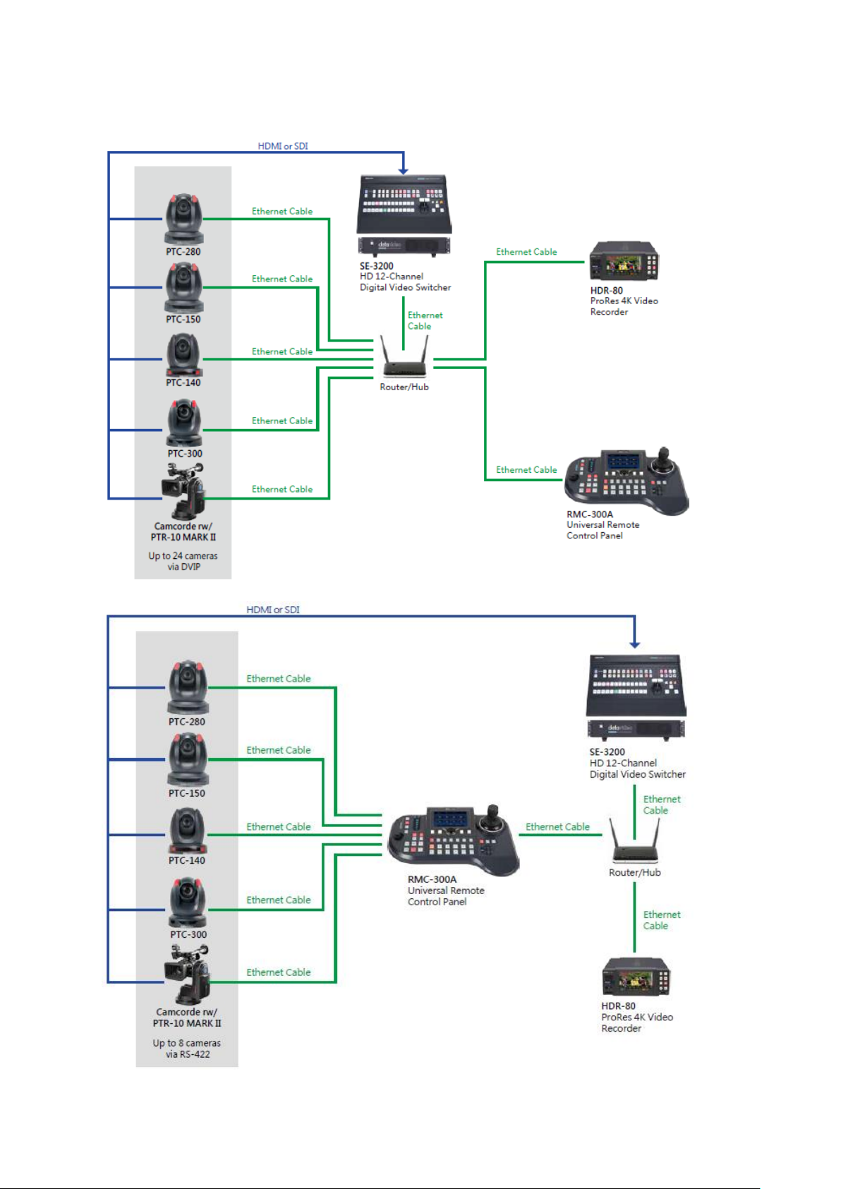
1.2 System Diagram
8
Page 9
2. Connections and Controls
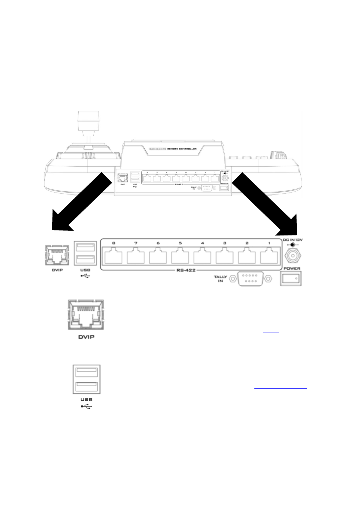
DVIP Control
The DVIP port connects the camera controller directly to the
PC or a network router via any RJ-45 cables, allowing the
controller to control up to 24 cameras. See DVIP for more
details.
USB 2.0 Firmware Upgrade Port
Connect the USB storage device to the USB firmware
upgrade port for firmware upgrade. See Firmware Update
for instructions.
In this chapter, we will first describe the rear panel ports for establishing connections with
external devices. In the second section, we will discuss panel operations.
2.1 Rear Panel
9
Page 10
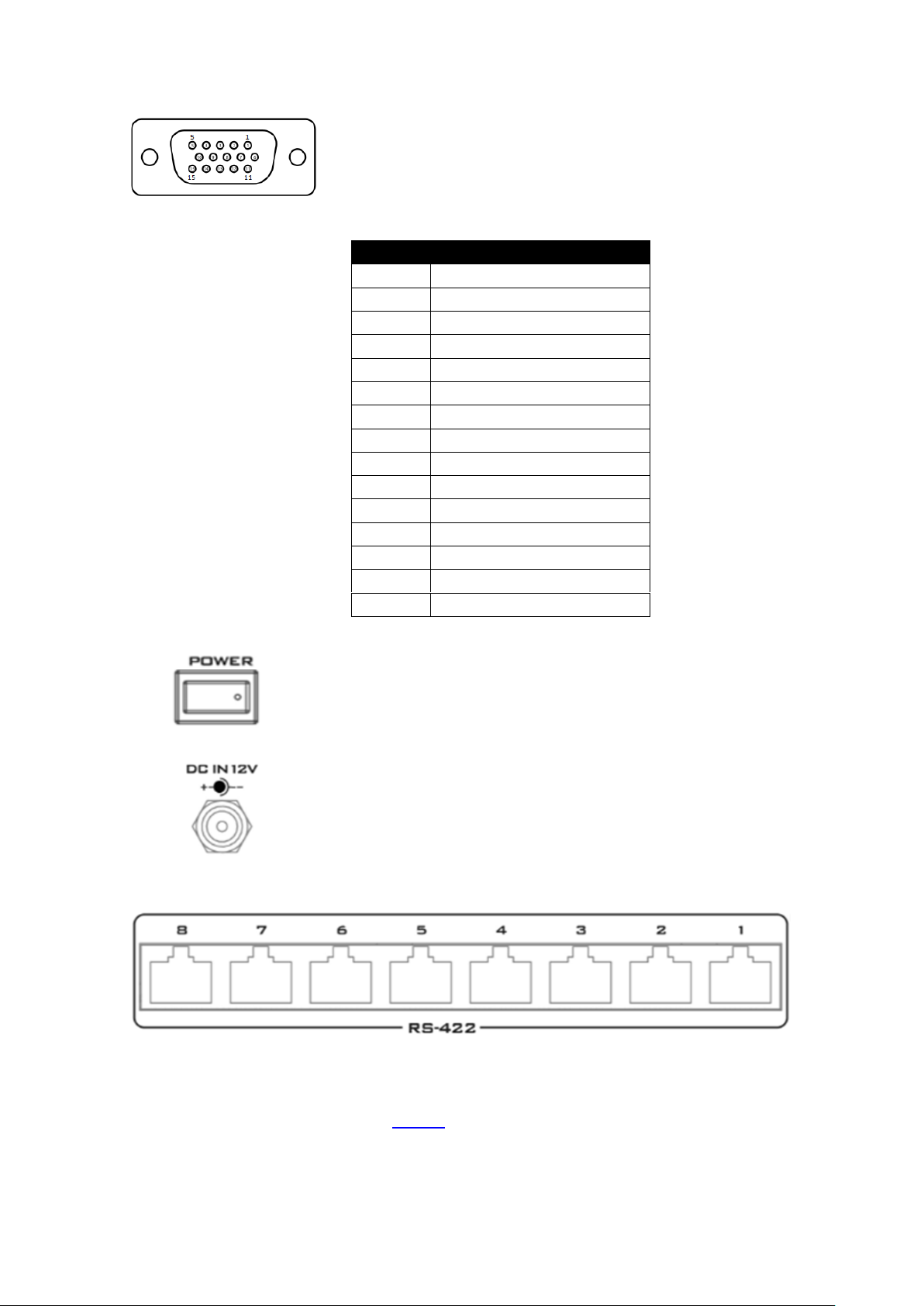
Tally IN Port
The D-sub 15 pin female Tally IN port receives tally signals
from the connected switcher’s tally out. Red indicates OnAir, and Green indicates next camera source.
The following table shows the pinout of the tally in jack.
Pin
Function
1
Program Channel 1
2
Program Channel 5
3
Preview Channel 1
4
GND
5
Program Channel 4
6
Program Channel 2
7
Program Channel 6
8
Preview Channel 2
9
GND
10
Preview Channel 5
11
Program Channel 3
12
Preview Channel 6
13
Preview Channel 3
14
GND
15
Preview Channel 4
Power Switch
Power switch ON/OFF
DC IN
DC in socket connects the supplied 12V PSU. The connection
can be secured by screwing the outer fastening ring of the
DC In plug to the socket.
8 Serial Communication Ports
On rear panel of the RMC-300A, there are 8 RJ-45 communication ports designed for
establishing direction connection with PTZ cameras. The communication protocol used here
is RS-422, allowing you to connect the controller to RS-422 ports of PTZ cameras (example:
PTC-150) using any RJ-45 cables. See RS-422 section for setup details.
Note: Before establishing connections with cameras, first make sure that they are already
set to RS-422 connection mode.
10
Page 11
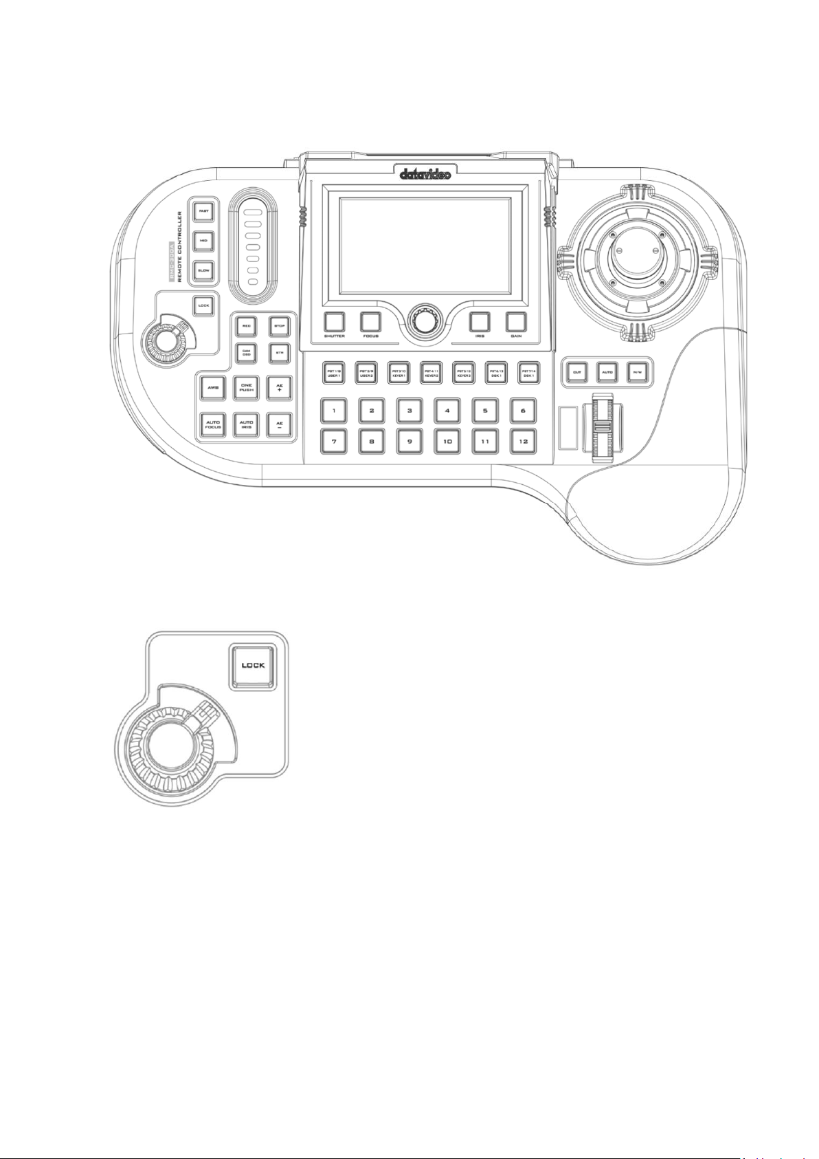
2.2 Operation Panel
VR Knob – Zoom
ZOOM – Twist the joystick clockwise (to the right) or anti-
clockwise (to the left) to zoom in or out the selected PTZ
camera.
Note: Make sure the LOCK button is not enabled. If the
LOCK button LED is ON, the joystick is locked; press the
LOCK button to unlock the joystick.
LOCK Button
When enabled, the joystick will be in the lock state. To
resume its functional status, simply press the button once
to unlock the joystick.
Camera Control
11
Page 12
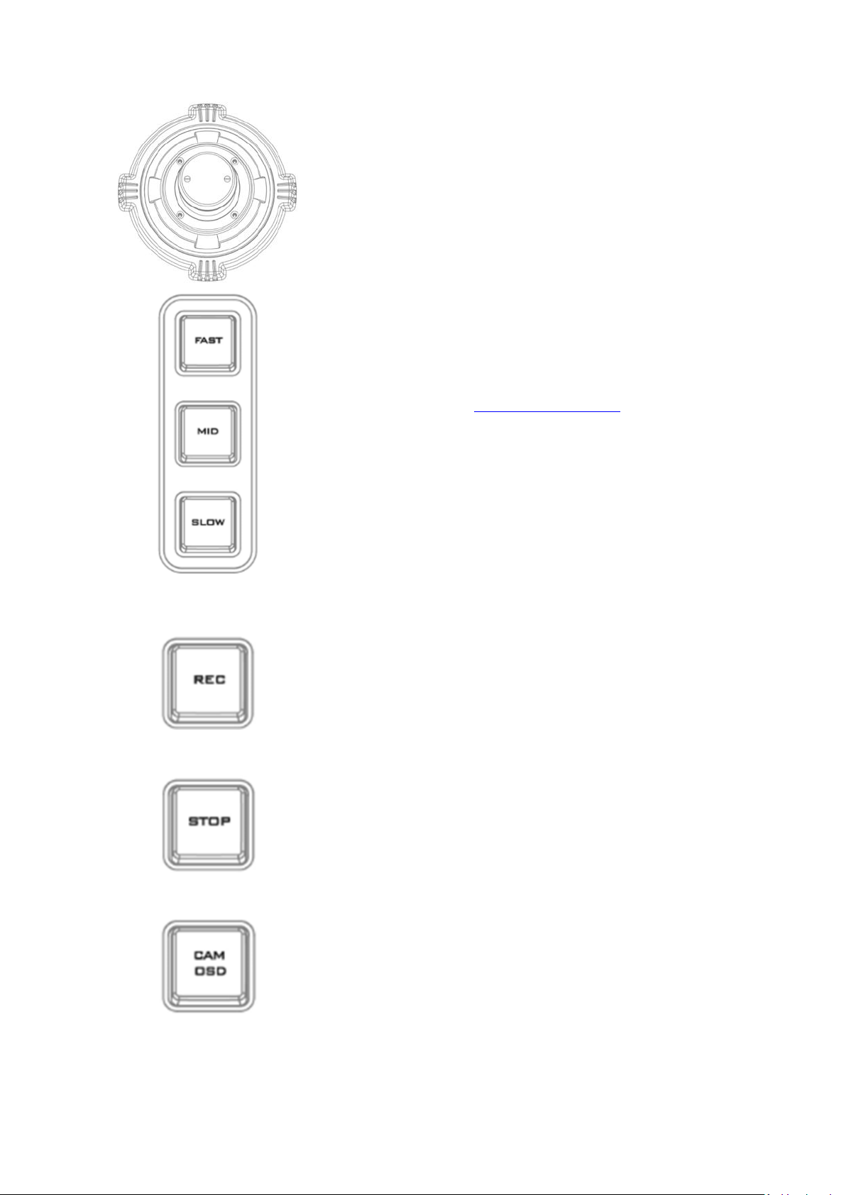
Joystick – PAN / TILT
PAN – Move the joystick left or right to pan the selected
PTZ camera from left to right or vice versa.
TILT – Move the joystick up or down to tilt the selected PTZ
camera up or down.
PTZ Speed Selection Buttons
The speed at which the selected camera moves can be
chosen by pressing one of the three speed buttons (Fast,
MID and Slow).
Note: When the joystick is pushed all the way to the
edges, the PTZ speed can also increase. You may select
the increase style in Joystick Speed Mode.
Browsing the OSD menu – Use the P/T joystick to move
between options and select.
Note: Before attempting to use the joystick to PAN or TILT
a selected camera, first make sure the LOCK button is not
enabled. If the LOCK button LED is ON, the joystick is
locked; press the LOCK button to unlock the joystick.
Recorder Activation Button (REC)
Press the REC button to activate recording on HDR-80/90
(Currently unavailable).
Recorder Deactivation Button (STOP)
Press the STOP button to de-activate recording on HDR80/90 (Currently unavailable).
CAM OSD Button
Pressing the CAM OSD button opens OSD menu of the
selected camera, then use the P/T joystick to browse and
select the menu options. See the camera user manual for
instructions on how to set your camera.
12
Page 13

STR (Memory) Button
Press the STR button to enter the RMC-300A into STORE
MODE. When activated, this allows the current camera
position to be stored in a chosen Preset Button by pressing
the corresponding preset button.
Press again to exit STORE MODE.
White Balance
Certain light conditions can cause discoloration of your
image. White balance allows you to adjust the color
balance in order to produce the best image quality.
Automatic White Balance (AWB)
Push to enable automatic white balance adjustment.
One Push White Balance
The One Push White Balance mode is a fixed white balance
mode that is automatically adjusted at the user’s request
(button push). The One Push White Balance data is lost
when the power is turned off, in other words, turning off
the machine power resets the One Push White Balance
setting.
The One Push White Balance mode can also be used for
white balance calibration. Zoom in the camera lens on a
white piece of paper which basically serves as a reference
for what is white, then press the PUSH AUTO button to
balance other colors accordingly.
AE+ Button
Press AE+ button to enable automatic exposure mode. The
selected camera will automatically increase exposure by
adjusting shutter and iris according to the subject’s
brightness.
AE- Button
Press AE- button to enable automatic exposure mode. The
selected camera will automatically decrease exposure by
adjusting shutter and iris according to the subject’s
brightness.
13
Page 14

AUTO FOCUS Button
Press the AUTO FOCUS button to enable auto focus
adjustment of the selected camera.
AUTO IRIS Button
Press the AUTO IRIS button to enable auto iris adjustment
of the selected camera.
The 5 inch color touch screen
displays the 4-in-1 OSD menu of
camera, switcher, recorder and
RMC-300A.
The knob allows the user to
manually adjust the camera’s
shutter speed, focus, iris and gain.
14
Page 15

SHUTTER Button
Press to enable manual
adjustment of the shutter
speed.
IRIS Button
Press to enable manual
adjustment of the lens iris.
Note: Make sure the AUTO IRIS
button is deactivated.
FOCUS Button
Press to enable manual
adjustment of the focus.
Note: Make sure the AUTO
FOCUS button is deactivated.
GAIN Button
Press to enable manual
adjustment of the gain or
brightness.
Transition Scroll Wheel
The wheel triggers transition of PVW and PGM views
(currently not available).
CUT Button
Pressing the Cut button performs immediate manual switch
between PVW and PGM views without the transition effect
(Currently unavailable).
MIX/WIPE Button
Pressing the M/W button selects either MIX or WIPE
transition effect which can be activated by either moving
the transition scroll wheel or pressing the AUTO button
(Currently unavailable).
AUTO Button
Pressing the Auto button automatically transitions PVW
and PGM views according to the selected transition effect
(Currently unavailable).
Switcher Control
15
Page 16

Camera Preset / Switcher Multi-Functional Composite Keys
The above composite keys allow you to save and recall PTZ settings in/from camera presets
or activate the corresponding switcher functions as labelled. In this section, the Camera
Preset buttons (PST 1/8 – PST 7/14) will be referred to as the PST button, the User Memory
buttons (USER 1 and USER 2) for accessing the switcher’s system settings will be referred to
as the USER button, the Keyer function buttons (KEYER 1 – KEYER 3) for accessing the
switcher’s keyer settings will be referred to as the KEYER button, and the DSK function
buttons (DSK 1 and DSK 2) for accessing the switcher’s DSK settings will be referred to as the
DSK button.
Follow the steps below to save and recall PTZ settings to/from presets:
1. Pan, tilt and zoom your camera.
2. On the 5” touchscreen, tap the Preset button to activate Presets 1 – 7 or tap the
Preset Shift button to activate Presets 8 – 14.
Note: Camera preset composite keys should illuminate purple if presets 1 – 7 are selected
and cyan if presets 8 – 14 are selected.
3. On the physical control panel, press the STR button which should illuminate red after that.
4. Now, on the physical control panel, press the PST button to which the PTZ settings should
be assigned.
5. After the save is complete, the STR button should illuminate white and the selected PST
button should illuminate red.
6. To RECALL a preset, first select a camera by pressing a Camera Selection Composite Key
(see the next section), then press the corresponding PST button to pan, tilt and zoom the
camera to the saved PTZ position.
The USER buttons allow access to the switcher’s system settings (currently unavailable).
The KEYER buttons allow access to the switcher’s Keyer settings (currently unavailable).
The DSK buttons allow access to the switcher’s DSK settings (currently unavailable).
16
Page 17

Camera Selection Composite Keys 1/13 – 12/24
Keyboard Brightness Slider
The LED style slider adjusts the keyboard brightness (currently
unavailable).
Each Camera Selection Composite Key allows you to select up to two camera numbers as
labelled. To switch between cameras 1-12 and cameras 13-24, simply press the Camera
Shift button on the touch screen.
Keyboard Brightness Control
17
Page 18

3. OSD MENU
Camera
Tap to enable Camera Selection Composite Keys, which should
illuminate yellow (the color of the camera button), indicating that the
keys are activated for selection of cameras 1 to 12.
Preset
Tap to enable Camera Preset / Switcher Multi-Functional Composite
Keys, which should illuminate purple (the color of the Preset button),
indicating that the keys are activated for selection of presets 1 to 7.
Camera Shift
Tap to switch the color of Camera Selection Composite Keys, to dark
green (the color of the Camera Shift button), indicating that the keys
are activated for selection of cameras 13 to 24.
Preset Shift
Tap to enable Camera Preset / Switcher Multi-Functional Composite
Camera Settings
Serial Port Parameters
This chapter provides descriptions of various functions in the OSD menu.
Locate and turn on the device’s power switch at the rear panel, after which the 5
inch color touch screen should display the 4-in-1 OSD menu of camera, switcher,
recorder and RMC-300A.
Note: The Switcher and Recorder functions are currently unavailable.
3.1 Camera
The control interface allowing the user to operate connected cameras is illustrated below.
The bottom row of buttons is described below:
18
Page 19

Keys, which should illuminate light blue (the color of the Preset Shift
button), indicating that the keys are activated for selection of presets 8
to 14.
Camera Settings
Tap camera icon to open the camera configuration page.
The options are described below.
Shutter
Displays the camera’s shutter speed such as 1/30.
Note: This field currently works for PTC-150 PTZ camera only.
Gain
Currently unavailable.
Focus
Displays the camera’s focus mode such as AF, or auto focus.
Video Mode
Currently unavailable.
White Balance
Displays the camera’s white balance mode such as WB Auto or auto white balance.
If the camera is in manual white balance mode, you may tap to open the
configuration page.
19
Page 20

MWB Pro stands for manual white balance professional, allowing the user to manually
adjust white balance by dragging red and green gain sliders on the configuration page.
Video Setting
Tap to open the camera video configuration page.
Note: For PTC-150 and PTC-200 PTZ cameras, only video mode, video orientation and
3DNR are allowed for configuration; for PTC-140, PTC-280 and PTC-300 PTZ cameras, the
rest of setting options other than video mode, video orientation and 3DNR are allowed for
configuration.
20
Page 21

Video Mode
Currently unavailable.
Video Orientation
You can select the following video orientations as shown in the diagram below. Selecting
OFF disables this option.
Other Video Settings (Currently unavailable)
3DNR
Contrast
Sharpness
Saturation
Exposure
Hue
AGC
Gamma
HDR (High Dynamic Range)
Audio Setting
Currently unavailable.
21
Page 22

Serial Port Settings
Gear Icon
Tap the gear icon on the “Camera” page to open the serial port configuration page.
Descriptions of the displayed options are outlined below. Please note that the “Serial Port
Configs” page is currently unavailable.
Baud Rate: Available rates are listed as follows.
9600
19200
38400
57600
115200
Data Bits: You can choose either 7 or 8 bits but the most frequently used data bit is 8 bits.
Parity: You can turn ON/OFF the parity bit.
Stop Bits: You can turn ON/OFF the stop bit.
Flow Control: You can turn ON/OFF flow control.
22
Page 23

3.2 RMC-300A
The RMC-300A’s system configuration interface is illustrated below.
Manage Device
Once you are in the device management page, you should be able to see function keys for
SCAN, LOAD and SAVE.
23
Page 24

Scan: After the Scan button is clicked, you will see a progress bar indicating the status of the
scan. Once the scan is complete, all of the connected devices within the same network
environment will be shown according to the order of the IP addresses.
Load: System will load the latest pre-saved order of the devices. After the Load button is
clicked, you will see a progress bar indicating the status of the load.
Save: System will memorize current order of the devices.
24
Page 25

System
On the System page, you will see the following function buttons.
Language
Currently unavailable.
Information
Tap to view the device information and upgrade device firmware.
Serial Port
Tap to enable/disable serial ports.
25
Page 26

ON: Cameras 1 – 8 are reserved for RS-422 connections.
Note: Cameras connected via DVIP while the serial port is enabled will be numbered from
9 – 24 as cameras connected to the serial ports take the priority over numbers from 1 – 8.
OFF: Cameras 1 – 24 are reserved for DVIP connection.
Network Setting
Tap to modify network settings.
The network options are described below:
Host Name: Tap to open an on-screen keyboard to modify the device name.
26
Page 27

Model Name: RMC-300A (cannot be modified)
DHCP: If enabled, the IP address will be automatically assigned by the router; if disabled, tap
the following options to open a number keyboard and enter relevant settings.
IP Address
Network Mask
Gateway
Primary DNS
Secondary DNS
MAC Address: 11:22:33:44:55:66 (cannot be modified)
After you have finished configuring the network settings, tap Save at the top right corner to
save new settings. To reset, simply tap the Reset button.
Camera Tally
Currently unavailable.
27
Page 28

Joystick Speed Mode
Nonlinear:
Speed increases exponentially.
Arithmetic:
Speed increases linearly.
Fixed:
Speed remains constant.
The panning and tilting speed will increase when you push the joystick all the way to the
limit. The joystick speed mode allows you to set the acceleration mode. The options are
Nonlinear, Arithmetic and Fixed.
Screen Saver
The screen saver can be automatically activated after the device is idle for a period of time.
The slider sets the time to activate the screen saver which is basically a black screen on the 5”
LCD display. To deactivate the screen saver and wake up RMC-300A, simply tap any point on
the screen.
28
Page 29

4. Device Setup
Cannot connect to Camera 9.
Please reboot that device then scan again.
In this chapter, we will show you how you can connect the RMC-300A controller to multiple
cameras via DVIP or RS-232 connection and operate cameras using your RMC-300A
controller.
Please note that you will be prompted of an error message if connection to the camera
fails. An example of the error prompt is shown below.
4.1 DVIP
DVIP is a communication protocol designed by Datavideo for transfer of data between
network devices. The diagram below best illustrates the connection between RMC-300A
and multiple cameras via DVIP.
29
Page 30

First, connect the RMC-300A and Datavideo cameras to a router via DVIP ports using
Ethernet cables. If the RMC-300A and the cameras are already set to DHCP, their IP
addresses will be automatically assigned by the router. If the connection mode is set to
static IP, you will then need to manually configure the network settings.
Note: RMC-300A’s network setting is DHCP by default.
To access or modify the RMC-300A’s network settings, tap “RMC-300A” at the top right
corner of the touch screen then tap “System” at the bottom right corner to open the system
configuration page.
Tap “Network Setting” then select DHCP or Static IP according to your network preference.
30
Page 31

DHCP
Enable DHCP mode if you would like your device IP address be assigned dynamically by the
router. Connect the RMC-300A to the router via the DVIP port.
Static IP
To connect using Static IP, simply disable DHCP mode and manually configure the following
according to your network environment:
IP Address
Network Mask
Gateway
Primary DNS
Secondary DNS
After you have configured your static IP settings, you can then connect the DVIP port of your
RMC-300A to the router and the connection will be immediately established.
Note: The gateway IP should be set to the router IP; the first three octets of the IP
addresses of the RMC-300A and the gateway IP should be identical.
Because Static IP involves advanced settings, please contact your IT department for further
assistance.
See the camera’s user manual for its DVIP connection settings.
An example of the static IP settings is illustrated below:
31
Page 32

4.2 RS-422
There are 8 RS-422 ports on the rear panel of RMC-300A. Each port can only connect one
camera at a time. The diagram below best illustrates the connection between the RMC300A and multiple cameras via RS-422.
32
Page 33

You can use a custom made RJ-45 cable to connect the RMC-300A to any Datavideo camera.
RMC-300A Controller
PTZ Camera
GND
1
Orange/White
Orange/White
1
GND
NC 2 Orange
Orange
2
NC
TX-
3
Green/White
Green/White
3
RX-
RX- 4 Blue
Blue
4
TX-
RX+
5
Blue/White
Blue/White
5
TX+
TX+ 6 Green
Green
6
RX+
NC
7
Brown/White
Brown/White
7
NC
NC 8 Brown
Brown
8
NC
GND
Please make the connection cable according to the pinout information described below.
Note: If you experience difficulties in making your RS-422 connection cable, please contact
your local dealer or Datavideo office for further assistance and recommendations.
See the camera’s user manual for its RS-422 connection settings.
After you’ve successfully established device connections, please tap “RMC-300A” on the
touch screen then tap “System” to open the configuration page as shown below. Tap “Serial
Ports” to enable RS-422 connection.
Note: Cameras connected via DVIP while the serial port is enabled will be numbered from
9 – 24 as cameras connected to the serial ports take the priority over numbers from 1 – 8.
33
Page 34

After you’ve enabled the serial port, go back to the “Camera” page on the touch screen and
tap the gear icon to open the Serial Port configuration page as shown below.
Note: The “Serial Port Configs” page is currently unavailable.
Below are descriptions of various RS-422 configuration options:
Baud Rate: Available rates are listed as follows.
9600
19200
38400
57600
115200
Data Bits: You can choose either 7 or 8 bits but the most frequently used data bit is 8 bits.
Parity: You can turn ON/OFF the parity bit.
Stop Bits: You can turn ON/OFF the stop bit.
Flow Control: You can turn ON/OFF flow control.
34
Page 35

5. Firmware Update
Datavideo usually releases new firmware containing new features or reported bug fixes
from time to time. Customers can either download the RMC-300A firmware as they wish or
contact their local dealer or reseller for assistance.
This section outlines the firmware upgrade process which should take approximately a few
minutes to complete.
The existing RMC-300A settings should persist through the firmware upgrade process,
which should not be interrupted once started as this could result in a non-responsive unit.
1. Go to the official product page to download the latest firmware file to the datavideo
folder on the USB disk (F:/datavideo/rmc300a_fwup).
Note: The directory name, datavideo, must be in lower case, and the firmware file
name must not contain any extension and must not be renamed.
2. Plug the USB disk containing the latest firmware file into the USB 2.0 Firmware
Upgrade Port, then turn ON the RMC-300A.
3. After the RMC-300A has been powered ON successfully, then at the top right corner of
the UI on the LCD screen, tap RMC-300A then System.
35
Page 36

4. On the System page, tap the version number in Information.
5. On the Information page, tap the Update button.
36
Page 37

6. While the firmware is being updated, you will be prompted as shown below.
7. Reboot your RMC-300A after the firmware has been successfully updated.
37
Page 38

6. Dimensions
RMC-300A
Unit: Millimeters (mm)
38
Page 39

7. Specifications
Model Name
RMC-300A
Product Name
Universal Remote Control Panel
Maximum Camera Control
24
Preset (Position)
14 for each camera
Control Protocol
DVIP, DHCP Client
Connection to Camera
RS-422, Ethernet
Input/Output
USB 2.0 x 2
10/100 Mbps Ethernet (RJ-45 connector) x 1
RS-422 (RJ-45 connector) x 1
Built in Monitor
Size: 5”
Resolution: 1280 x 720
Firmware Update
USB 2.0
Dimensions
420 x 294 x 134 mm
Weight
1.504 Kg
Operating Temperature
0°C – 40°C (32°F – 104°F)
Storage Temperature
-10°C – 60°C (14°F – 140°F)
Operating Humidity
10% to 80% (non-condensing)
Power
DC 12V, 19W
39
Page 40

Mar-19.2021
Version E3
Datavideo Technologies Co., Ltd. All rights reserved 2020
www.datavideo.com/product/RMC-300A
 Loading...