

Page 1
Page 2

Contents
Contents .............................................................................................. 2
Warnings and Precautions ................................................................. 3
Warranty .............................................................................................. 4
Standard Warranty ....................................................................... 4
Two Year Warranty ...................................................................... 4
Disposal ............................................................................................... 4
1. Produ ct Overview ............................................................................ 5
1.1 Features ................................................................................ 5
2. Overview of Connections & Controls ............................................ 6
2.1 Control Panel Overview ......................................................... 6
2.2 Rear Panel Terminals ............................................................ 7
3. Keyboard Controls .......................................................................... 8
3.1 User Memory & WIPE Transition Combination Keys .............. 8
3.2 Program Source Row............................................................. 9
3.3 Preview Source Row ........................................................... 10
3.4 Transition and Transition Effect ........................................... 12
3.5 Keyer Assignment and Adjustment ...................................... 13
4. Configuration and Debug Mode ................................................... 14
4.1 Enter Configuration and Debug Mode .................................. 14
4.2 Selection of Configuration and Debug Mode Functions ....... 14
4.3 USER 1 – Version Display ................................................... 15
4.4 USER 2 – LED Brightness Adjustment and Memory ............ 16
4.5 USER 3 – Button Functional Check ..................................... 16
4.6 USER 4 – T-Bar and Knob Functional Check ...................... 16
4.7 USER 5 – Exit Configuration and Debug Mode .................... 17
5. Firmware Update ........................................................................... 18
6. Frequently-Asked Quest ions ........................................................ 18
7. Dimensions .................................................................................... 19
8. Specifications ................................................................................ 19
9. Service and Support ..................................................................... 20
Disclaimer of Product and Services
The information offered in this instruction manual is intended as a guide only. At all times, Datavideo Technologies will try to
give correct, complete and suitable information. However, Datavideo Technologies cannot exclude that some information in
this manual, from time to time, may not be correct or may be incomplete. This manual may contain typing errors, omissions
or incorrect information. Datavideo Technologies always recommend that you double check the information in this
document for accuracy before making any purchase decision or using the product. Datavideo Technologies is not responsible
for any omissions or errors, or for any subsequent loss or damage caused by using the information contained within this
manual. Further advice on the content of this manual or on the product can be obtained by contacting your local Datavideo
Office or dealer.
2
Page 3

Warnings and Precautions
1. Read all of these warnings and save them for later reference.
2. Follow all warnings and instructions marked on this unit.
3. Unplug this unit from the wall outlet before cleaning. Do not use liquid or aerosol cleaners. Use a
damp cloth for cleaning.
4. Do not use this unit in or near water.
5. Do not place this unit on an unstable cart, stand, or table. The unit may fall, causing serious
damage.
6. Slots and openings on the cabinet top, back, and bottom are provided for ventilation. To ensure
safe and reliable operation of this unit, and to protect it from overheating, do not block or cover
these openings. Do not place this unit on a bed, sofa, rug, or similar surface, as the ventilation
openings on the bottom of the cabinet will be blocked. This unit should never be placed near or
over a heat register or radiator. This unit should not be placed in a built-in installation unless
proper ventilation is provided.
7. This product should only be operated from the type of power source indicated on the marking
label of the AC adapter. If you are not sure of the type of power available, consult your
Datavideo dealer or your local power company.
8. Do not allow anything to rest on the power cord. Do not locate this unit where the power cord
will be walked on, rolled over, or otherwise stressed.
9. If an extension cord must be used with this unit, make sure that the total of the ampere ratings
on the products plugged into the extension cord do not exceed the extension cord rating.
10. Make sure that the total amperes of all the units that are plugged into a single wall outlet do not
exceed 15 amperes.
11. Never push objects of any kind into this unit through the cabinet ventilation slots, as they may
touch dangerous voltage points or short out parts that could result in risk of fire or electric
shock. Never spill liquid of any kind onto or into this unit.
12. Except as specifically explained elsewhere in this manual, do not attempt to service this product
yourself. Opening or removing covers that are marked “Do Not Remove” may expose you to
dangerous voltage points or other risks, and will void your warranty. Refer all service issues to
qualified service personnel.
13. Unplug this product from the wall outlet and refer to qualified service personnel under the
following conditions:
a. When the power cord is damaged or frayed;
b. When liquid has spilled into the unit;
c. When the product has been exposed to rain or water;
d. When the product does not operate normally under normal operating conditions. Adjust only
those controls that are covered by the operating instructions in this manual; improper
adjustment of other controls may result in damage to the unit and may often require
extensive work by a qualified technician to restore the unit to normal operation;
e. When the product has been dropped or the cabinet has been damaged;
f. When the product exhibits a distinct change in performance, indicating a need for service.
3
Page 4

Warranty
Standard Warranty
• Datavideo equipment is guaranteed against any manufacturing defects for one year from the
date of purchase.
• The original purchase invoice or other documentary evidence should be supplied at the time of
any request for repair under warranty.
• Damage caused by accident, misuse, unauthorized repairs, sand, grit or water is not covered by
this warranty.
• All mail or transportation costs including insurance are at the expense of the owner.
• All other claims of any nature are not covered.
• Cables & batteries are not covered under warranty.
• Warranty only valid within the country or region of purchase.
• Your statutory rights are not affected.
Two Year Warranty
• All Datavideo products purchased after 01-Oct.-2008 qualify for a free one
year extension to the standard Warranty, providing the product is
registered with Datavideo within 30 days of purchase. For information on
how to register please visit www.datavideo.com or contact your local
Datavideo office or authorized Distributors
• Certain parts with limited lifetime expectancy such as LCD Panels, DVD Drives, Hard Drives are
only covered for the first 10,000 hours, or 1 year (whichever comes first).
Any second year warranty claims must be made to your local Datavideo office or one of its authorized
Distributors before the extended warranty expires.
Disposal
For EU Customers only - WEEE Marking
This symbol on the product indicates that it should not be treated as household
waste. It must be handed over to the applicable take-back scheme for the recycling
of Waste Electrical and Electronic Equipment. For more detailed information about
the recycling of this product, please contact your local Datavideo office.
4
Page 5

1. Product Overview
The RMC-260 is a cost effective controller designed specifically for the SE-1200MU Digital Video
Switcher. The RMC-260 interfaces with the SE-1200MU via an RS-232 interface.
The RMC-260 is designed to be a user switcher-style controller to allow easy & quick control SE1200MU, with hard keys for the main switcher functions and on-screen menu controls for quick & easy
adjustment of parameters in the field.
The RMC-260 can be used with or without the PC Control Software, although the PC Control software
must still be used for Software Upgrades and Import/Export of UserMems, Stills, and Clips.
That’s Datavideo, sharing the value!
1.1 Features
• A switcher style keyboard for SE-1200MU operation
• Clear key definitions
• Support Keyers enable and quick function assignment
• Save user behaviour to user memory keys for quick access
• Two keyers with two corresponding knobs for assignment of Keyer 1/2 sources
• XPT (Cross Point Assignment)
• Take button to switch between PVW and PGM views
• FTB button fades the PGM view to a black screen
• Still Grab function for capturing instantaneous video image
• RS-232 interface for communication between RMC-260 and SE-1200MU
• Bright LED lighting
5
Page 6
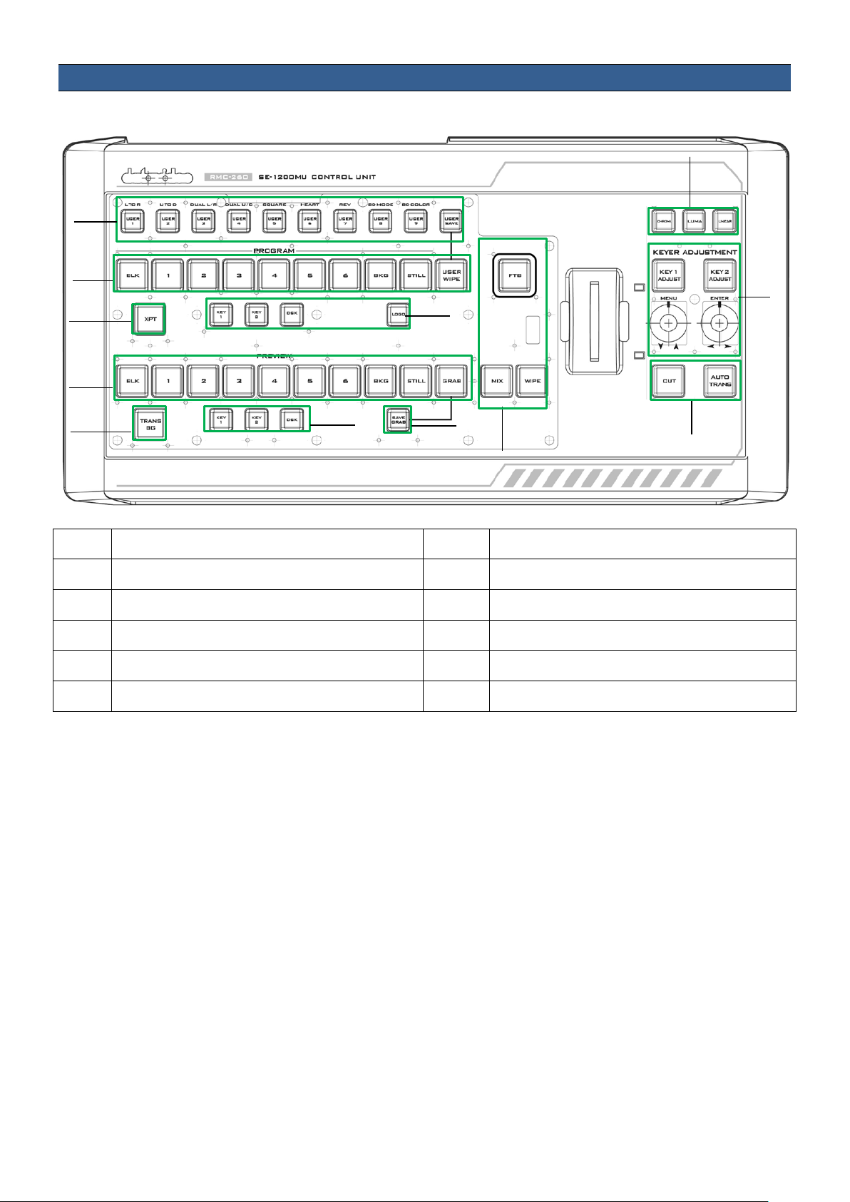
2. Overview of Connecti ons & Cont rols
3
2
1
12
5
9
10
4
6
7
8
11
2.1 Control Panel Overview
1 User Memory & WIPE Transition Selection 7 Keyers / DSK Function on PVW
2 Program Source Row 8 Save Grab Image
3 XPT Cross-Point Function 9 Transition Effect
4 Keyers / DSK Function on PGM 10 Keyer Assignment Button Row
5 Preview Source Row 11 Keyer Adjustment / Menu Control
6 Background Transition 12 Transition
6
Page 7

2.2 Rear Panel Terminals
Power ON/OFF
Switches the power ON/OFF
DC In Socket
Connect the supplied 12V PSU to this socket. The connection
USB Firmware
For connection to PC during the firmware upgrade process
RS-232 Interface
RS-232 interface for communication between RMC-260 and SE-
Switch
can be secured by screwing the outer fastening ring of the DCIN plug to the socket.
Upgrade
1200MU
Note: It takes about 2-3 seconds for the RMC-260 indicator to
be turned off after the RS-232 connection is removed.
7
Page 8

3. Keyboard Controls
USER SAVE button will take precendence over the USER WIPE button.
3.1 User Memory & WIPE Transition Combination Keys
User Memory buttons 1-9: The User buttons are a shortcut way of loading previously saved user
configurations, thus allowing the user to recall the last saved switcher settings.
USER SAVE
Pressing this button allows selection of the User Memory number from the User
Memory button row for saving user defined settings.
After the USER SAVE button is pressed, the USER SAVE button LED will be turned on
and the USER 1-9 buttons will start flashing. Pick and press one USER button, all
other USER buttons will be turned off except the selected USER button (USER SAVE
button will remain ON). After the User settings are saved successfully, the selected
USER button and the USER SAVE button will be turned off.
When the USER SAVE button and the USER WIPE button are OFF, the user defined
settings may be recalled by pressing one of the USER buttons from the USER
memory button row.
When the USER SAVE button and the USER WIPE button are ON at the same, the
WIPE Transition Selection: There are a total of 6 wipe transition types with details of each described in
the table below.
L TO R
Wipe from left to right.
DUAL U/D
Wipe from Top and Bottom to
Centre.
U TO D
Wipe from top to bottom.
SQUARE
Box Wipe from Centre to outside
edges.
DUAL L/R
Wipe from Left and Right
sides to Centre.
8
HEART
Heart Wipe from Centre to outside
edges.
Page 9

REV
When the REV button is ON then the selected transition will operate in the reverse
direction only.
After the desired WIPE transition effect is selected, the user may turn on the WIPE border by pressing
the BD MODE button and apply the border color by pressing the BD COLOR button.
BD MODE
Border width increment /
BD COLOR
Optional color border applied
decrement
3.2 Program Source Row
The Program row of buttons is for control of the program output, which is the live output. You can
switch or CUT from one video source to another directly on the Program row. You will see the PGM
output changes as you press different keys along this top row of buttons.
Buttons 1, 2, 3, 4, 5 and 6: Video source buttons.
BLK button: Black background for use on the Program row.
BKG button: Background button that assigns a background color or color bars for use on the Program
row.
STILL button: Press this button to cycle through Live Video, Freeze and Still.
USER WIPE: Press this button to swap between User Memory function and WIPE transition function.
WIPE is enabled after USER WIPE button is ON. When the USER SAVE button and the USER WIPE button
are ON at the same time, the USER SAVE button will take precendence over the USER WIPE button.
STILL: Press to cycle through Live Video/Freeze/Still of PGM
Note: If you are not sure what you are seeing is Freeze or Still, please enable the Multiview label info.
9
Page 10

PGM XPT
Video source and channel assignments in accordance with the user’s preference.
Press an output button on the Program row and the selected output button
lected input on the Preview row is assigned to the
The user may continue the assignment by pressing another output button on
PGM KEY 1
PGM KEY 2
PGM DSK
PGM LOGO
1. First press the XPT button. Buttons of Program and Preview rows will flash.
2.
will turn red.
3. Press an input button on the Preview row and the selected input button will
turn green.
4. At this point, the se
corresponding output on the Program row.
5.
the program row or press the XPT button to complete the assignment.
Enable / Disable Keyer 1
Enable / Disable Keyer 2
3.3 Preview Source Row
The Preview row of buttons is for control of the Preview window. The Preview row sets the next
transitioned program by pressing the corresponding key to select the source.
Pressing DSK places logo or animations on the program view. Before placing the
DSK on the program view, make sure it is correct on the PVW screen first.
Display of pre-selected logo on the Preview and Program outputs
Buttons 1, 2, 3, 4, 5 and 6: Video source buttons.
BLK button: Black background for use on the Preview row.
10
Page 11

BKG button: Background button that assigns a background color or color bars for use on the Preview
specifies that the Background will be
this button allows the user to select the desired keyer function
this button allows the user to select the desired keyer function
this button allows the user to select the desired keyer function
row.
STILL button: Press this button to cycle through Live Video, Freeze and Still.
Note: If you are not sure what you are seeing is Freeze or Still, please enable the Multiview label info.
GRAB button: Pressing the GRAB button will capture a frame of video.
PVW TRANS BG
Background transition, TRANS BG
“transitioned” from the Program source to the Preview Source.
PVW KEY 1
Press to Enable / Disable Keyer 1 on Multiview and PVW Output or display
keyer type.
Press and hold
from the KEYER ASSIGNMENT ROW (labelled number 10 in the Control Panel
Overview section). As soon as Chroma/Luma/Linear buttons flash, press the
corresponding button once to select the desired keyer.
PVW KEY 2
Press to Enable / Disable Keyer 2 on Multiview and PVW Output or display
keyer type.
Press and hold
from the KEYER ASSIGNMENT ROW (labelled number 10 in the Control Panel
Overview section). As soon as Chroma/Luma/Linear buttons flash, press the
corresponding button once to select the desired keyer.
PVW DSK
Enable / Disable DSK on Multiview and PVW Output.
Press and hold
from the KEYER ASSIGNMENT ROW (labelled number 10 in the Control Panel
Overview section). As soon as Chroma/Luma/Linear buttons flash, press the
corresponding button once to select the desired keyer.
SAVE GRAB
Pressing the SAVE GRAB button to save the grabbed picture to storage media
11
Page 12

3.4 Transition and Transition Effect
T-Bar
CUT Button
AUTO TRANS Button
FTB
MIX Button
WIPE Button
The Transition Control controls what the “next” transition (mix, wipe, cut, Auto TRANS or the T-bar) will
do, i.e. they specify what is “in the transition.”
This performs a manually controlled transition from the current program
source to the selected Preview source. When the T-Bar has travelled as far as
it can go, the transition between sources is complete.
The CUT button is used to instantaneously switch between the currently
selected Program and a Preview source.
Instead of using the manually operated T-Bar, the Auto TRANS button is
used to automatically transition between the selected Program and a
Preview source over a set period.
Fade To Black, this button fades the current video program source to black.
When pressed again it acts in reverse from complete black to the currently
selected program video source.
The MIX button is selected when a dissolve transition between the selected
Program and a Preview source is required. This Mix transition is generated
by moving the T-Bar manually or Pressing the Auto TRANS button.
The WIPE button is selected when a wipe effect transition between the
selected Program and a Preview source is required. This WIPE effect is
generated by moving the T-Bar manually or by pressing the Auto button.
Clip transition mode is activated when MIX/WIPE buttons are enabled
simultaneously.
12
Page 13

3.5 Keyer Assignment and Adjustment
CHROMA
LUMA
LINEAR
KEYER ADJUSTMENT
rotate the left knob to move
3 seconds resets the MENU to their
Press to select Chroma Keyer
Press to select Luma Keyer
Press to select Linear Keyer
Press KEY 1/2 ADJUST buttons to activate the adjustment of the keyer type
assigned to KEY 1/2. The knob is designed for the user to fine-tune the keyer.
OSD MENU
• Press the left knob (MENU label) to open the OSD menu.
• To browse through the menu, simply
up/down the Main Menu Options
• Press the right knob (ENTER label) to select an option on the Menu and
rotate the right knob to move left/right across the Sub-Menu Options.
• Press the right knob (ENTER label) to select a Sub-Menu Option and rotate
the right knob to adjust the parameter values.
• To exit a particular sub-menu option, press the left knob.
MENU RESET
Long-pressing the menu knob for 2factory defaults.
13
Page 14

4. Configuration and Debug Mode
4.1 Enter Configuration and Debug Mode
While SE-1200MU is not connected (all LEDs are white), simultaneously press USER 1 and USER SAVE
buttons and all button LEDs will flash; wait till all buttons return to white color and once the USER 1
button turns red, the device is in the Configuration and Debug Mode.
4.2 Selection of Configuration and Debug Mode Functions
Rotate the MENU knob below the KEY1 ADJUST button to cycle through USER 1-5 (F1-F5) and as you
rotate the MENU knob, you will see the USER 1-5 buttons turn red one at a time.
To enter a particular menu function, simply press the MENU knob.
To exit, press the MENU knob again.
The available functions are listed as follows:
USER 1 – Version information display
USER 2 – LED brightness adjustment and memory
USER 3 – Button functional check
USER 4 – T-Bar and knob functional check
USER 5 – Exit configuration and debug mode
14
Page 15

Bit 7
Bit 6
Bit 5
Bit 4
Bit 3
Bit 2
Bit 1
Bit 0
BLK 1 2 3 4 5 6
BKG
4.3 USER 1 – Version Display
Once the USER 1 button is selected after pressing the MENU knob, the user will immediately see some
buttons on the PROGRAM row turn red and some buttons on the PREVIEW row turn green, which
represent the current firmware version loaded on the device.
VERSION is displayed in HEX format. PROGRAM row indicates Major version digits, and PRESET row
indicates Minor version digits. BLK is the most significant bit and BKG is the least significant bit.
15
Page 16

4.4 USER 2 – LED Brightness Adjustment and Memory
To adjust the button LED brightness, simply press the MENU knob to select USER 2 button. Immediately
after the USER 2 button is selected, the user will see some or all of buttons BLK/1/2/3/4 turn red along
the PROGRAM row depending on the previous brightness setting.
• MENU Knob – Rotate left and right to adjust the LED brightness
• ENTER Knob – Press to save the current brightness setting and upon the knob press, KEY 2
ADJUST button will start flashing red. After the new setting is saved, KEY 2 ADJUST button will
remain constant red.
• DSK 2 Button – Flashing red indicates the SAVE is in progress and constant red indicates that
brightness level is successfully saved.
• Buttons BLK/1/2/3/4 along the PROGRAM row indicate the current LED brightness level.
4.5 USER 3 – Button Functional Check
Press the MENU knob to select USER 3 button to perform button functional check and press the MENU
knob to exit.
4.6 USER 4 – T-Bar and Knob Functional Check
Press the MENU knob to select USER 4 button to perform T-Bar and knob functional check.
PROGRAM row (BLK/1/2/3/4/5/6/BKG/STILL/USER WIPE) indicates T-Bar position, so moving T-Bar will
turn on/off the corresponding button LEDs along the PGM row.
KEY 1 ADJUST / KEY 2 ADJUST button LEDs indicate knob functionality. Rotate the knob right and the
KEY 2 ADJUST button will turn red and the KEY 1 ADJUST button remains white; rotate the knob left and
the KEY 1 ADJUST button will turn red and KEY 2 ADJUST button remains white.
16
Page 17

4.7 USER 5 – Exit Configuration and Debug Mode
To exit the configuration and debug mode, press the MENU knob to select the USER 5 button.
17
Page 18

5. Firmware Update
From time to time, Datavideo may release new firmware to either add new features or to fix reported
bugs in the current RMC-260 firmware. Customers can update the firmware themselves if they wish or
they can contact their local dealer or reseller for assistance should they prefer this method.
This section describes the firmware update process and it should take approximately few minutes to
complete. Once started, the update process should not be interrupted in any way as this could result in
a non-responsive unit.
Requirement
• Latest firmware update files (bootloader and application firmware)
• A USB cable not longer than 2 meters
• A Windows PC with USB 2.0 ports
1. Connect the PC to the F/W UPGRADE connector on the rear panel of the RMC-260 via a USB cable.
2. Connect the power and switch on the device.
3. The PC will automatically detect the RMC-260 device.
4. Remove firmware.bin file from the device.
5. Copy the latest firmware version file to the device.
6. Firmware update is complete after the firmware file is copied to the device.
7. Safely remove the USB device.
8. Switch off the RMC-260 power.
9. Remove the USB cable connection between the RMC-260 and the PC.
6. Frequently-Asked Quest ions
This section describes problems that you may encounter while using the RMC-260. If you have
questions, please refer to related sections and follow all the suggested solutions. If problem still exists,
please contact your distributor or the service center.
1. My PC Control Panel UI cannot work with the RMC-260.
The RMC-260 has to work with the PC Control Panel UI of the version SE-1200MU V1.2.0.7 or above.
2. While SE-1200MU is ON, loss of connection between SE-1200MU and RMC-260 is experienced after
hot plugging RS-232 connection repeatedly.
Loss of connection does not usually occur when hot plugging RS-232 connection repeatedly,
however, after 5 to 6 times, connection might be lost; wait for approximately 72 seconds, the
connection will be re-established.
18
Page 19

7. Dimensions
Baud Rate
19200 ODD
Firmware Update
USB
Input AC 100 ~ 240 V Switching Adapter
Output DC 12V
Power Consumption
5W
Operating Temperature
0°C to 50°C (32°F to 122°F)
Storage Humidity
10% to 90% (non condensing)
Dimension (mm)
430.0 x 216.5 x 69.6
Net Weight
1.28 Kg
Certification
CE, FCC
All measurements in millimetres (mm)
Communication Interface RS-232
Power Supply
8. Specifications
19
Page 20

9. Service and Support
20
 Loading...