

Page 1

1 2
Page 2

Table of Contents
WARNINGS AND PRECAUTIONS ........................................................... 4
WARRANTY ................................................................................................ 5
STANDARD WARRANTY ........................................................................................ 5
TWO YEAR WARRANTY ........................................................................................ 5
DISPOSAL .................................................................................................. 5
1. PRODUCT OVERVIEW ......................................................................... 6
2. FEATURES ............................................................................................. 6
3. LOCATION AND FUNCTION OF PARTS ............................................ 7
4. CONNECTIONS ...................................................................................... 8
4.1 CAMERA REAR CONTROL PANEL ....................................................................... 8
4.2 RECEIVER BOX FRONT PANEL ........................................................................... 8
4.3 RECEIVER BOX REAR PANEL ............................................................................. 8
5. SYSTEM DIAGRAM ............................................................................... 9
6. REMOTE CONTROL AND ON-SCREEN MENU .............................. 10
6.1 REMOTE CONTROL FUNCTIONS ...................................................................... 10
6.2 ON-SCREEN MENU ...................................................................................... 13
7. INSTRUCTION FOR INSTALLATION ................................................ 22
7.1 STEP 1 – DIP SWITCH SETTING ...................................................................... 22
7.2 STEP 2 – ONE END OF MOUNTING WIRE ......................................................... 22
7.3 STEP 3 – CEILING BRACKET (B) ...................................................................... 22
7.4 STEP 4 – CEILING BRACKET (A) AND CAMERA ................................................... 23
7.5 STEP 5 – MOUNT CAMERA TO CEILING ............................................................ 25
7.6 STEP 6 – SCREW TO SECURE CAMERA ............................................................. 26
7.7 STEP 7 – CABLE CONNECTION ........................................................................ 26
8. DIP SWITCH SETTINGS ..................................................................... 27
8.1 RS-422..................................................................................................... 27
8.2 IRID ......................................................................................................... 27
9. DVIP CONTROL PROTOCOL ............................................................ 28
Page 3

9.1 DVIP SETUP ............................................................................................... 28
9.2 DVIP CONTROL OPERATION GUIDE ................................................................ 31
10. RS-422 CONTROL PROTOCOL ...................................................... 42
10.1 RS-422 PIN DESCRIPTIONS ........................................................................ 42
10.2 RS-422 CONTROL OPERATION GUIDE ........................................................... 42
10.2.1 Overview of VISCA ......................................................................... 42
10.2.2 VISCA Communication Specifications ............................................ 43
10.2.3 VISCA Device Setting Command .................................................... 46
10.2.4 VISCA Command/ACK Protocol ..................................................... 46
10.2.5 VISCA Camera-Issued Messages ................................................... 47
10.2.6 PTC-150 Commands ...................................................................... 48
11. FIRMWARE UPDATE ........................................................................ 52
12. DIMENSIONS ..................................................................................... 53
13. SPECIFICATIONS .............................................................................. 55
14. SERVICE AND SUPPORT ................................................................ 57
Disclaimer of Product and Services
The information offered in this instruction manual is intended as a guide only. At all times,
Datavideo Technologies will try to give correct, complete and suitable information. However,
Datavideo Technologies cannot exclude that some information in this manual, from time to time,
may not be correct or may be incomplete. This manual may contain typing errors, omissions or
incorrect information. Datavideo Technologies always recommend that you double check the
information in this document for accuracy before making any purchase decision or using the
product. Datavideo Technologies is not responsible for any omissions or errors, or for any
subsequent loss or damage caused by using the information contained within this manual. Further
advice on the content of this manual or on the product can be obtained by contacting your local
Datavideo Office or dealer.
3
Page 4

Warnings and Precautions
1. Read all of these warnings and save them for later reference.
2. Follow all warnings and instructions marked on this unit.
3. Unplug this unit from the wall outlet before cleaning. Do not use liquid or aerosol cleaners.
Use a damp cloth for cleaning.
4. Do not use this unit in or near water.
5. Do not place this unit on an unstable cart, stand, or table. The unit may fall, causing serious
damage.
6. Slots and openings on the cabinet top, back, and bottom are provided for ventilation. To
ensure safe and reliable operation of this unit, and to protect it from overheating, do not
block or cover these openings. Do not place this unit on a bed, sofa, rug, or similar surface,
as the ventilation openings on the bottom of the cabinet will be blocked. This unit should
never be placed near or over a heat register or radiator. This unit should not be placed in a
built-in installation unless proper ventilation is provided.
7. This product should only be operated from the type of power source indicated on the
marking label of the AC adapter. If you are not sure of the type of power available, consult
your Datavideo dealer or your local power company.
8. Do not allow anything to rest on the power cord. Do not locate this unit where the power
cord will be walked on, rolled over, or otherwise stressed.
9. If an extension cord must be used with this unit, make sure that the total of the ampere
ratings on the products plugged into the extension cord do not exceed the extension cord’s
rating.
10. Make sure that the total amperes of all the units that are plugged into a single wall outlet do
not exceed 15 amperes.
11. Never push objects of any kind into this unit through the cabinet ventilation slots, as they
may touch dangerous voltage points or short out parts that could result in risk of fire or
electric shock. Never spill liquid of any kind onto or into this unit.
12. Except as specifically explained elsewhere in this manual, do not attempt to service this
product yourself. Opening or removing covers that are marked “Do Not Remove” may
expose you to dangerous voltage points or other risks, and will void your warranty. Refer all
service issues to qualified service personnel.
13. Unplug this product from the wall outlet and refer to qualified service personnel under the
following conditions:
a. When the power cord is damaged or frayed;
b. When liquid has spilled into the unit;
c. When the product has been exposed to rain or water;
d. When the product does not operate normally under normal operating conditions. Adjust
only those controls that are covered by the operating instructions in this manual;
improper adjustment of other controls may result in damage to the unit and may often
require extensive work by a qualified technician to restore the unit to normal operation;
e. When the product has been dropped or the cabinet has been damaged;
f. When the product exhibits a distinct change in performance, indicating a need for service.
4
Page 5

•
•
•
•
•
•
•
•
•
•
Warranty
Standard Warranty
Datavideo equipment is guaranteed against any manufacturing defects for one year from
the date of purchase.
The original purchase invoice or other documentary evidence should be supplied at the
time of any request for repair under warranty.
Damage caused by accident, misuse, unauthorized repairs, sand, grit or water is not
covered by this warranty.
All mail or transportation costs including insurance are at the expense of the owner.
All other claims of any nature are not covered.
Cables & batteries are not covered under warranty.
Warranty only valid within the country or region of purchase.
Your statutory rights are not affected.
Two Y ear Warranty
All Datavideo products purchased after 01-Oct.-2008 qualify for a free one year extension
to the standard Warranty, providing the product is registered with Datavideo within 30
days of purchase. For information on how to register please visit www.datavideo-tek.com
or contact your local Datavideo office or authorized Distributors
Certain parts with limited lifetime expectancy such as LCD Panels, DVD Drives, Hard
Drives are only covered for the first 10,000 hours, or 1 year (whichever comes first).
Any second year warranty claims must be made to your local Datavideo office or one of its
authorized Distributors before the extended warranty expires.
Disposal
For EU Customers only - WEEE Marking
This symbol on the product indicates that it will not be treated as
household waste. It must be handed over to the applicable take back
scheme for the recycling of electrical and electronic equipment. For
more detailed information about the recycling of this product, please
contact your local Datavideo office.
5
Page 6

1. Product Overview
The PTC-150T HD/SD Video Camera is a PTZ camera that can be mounted on a wall, ceiling, floor,
or a tabletop. The camera is equipped with HDBaseT Technology for remote control purpose,
video image conveyance, power transmission and Ethernet connection. The camera captures HD
video at 1920 x 1080 resolution, and features wide dynamic range with backlight compensation.
The camera features a motorized 30x optical zoom capability, and its image mirror and image
rotation functions allow you to electronically adjust the image and deliver a correctly oriented
image. In addition to the basic camera functions, the PTC-150T also has a receiver box that allows
the user to control the camera at a remote location with just one Ethernet cable.
50 programmable presets including pan, tilt, and zoom positions, allow the camera to quickly
move between predetermined camera positions using the remote, or an available PTZ controller.
For multi-camera shoots, the built-in tally light can identify active camera. The camera features a
built-in IR cut filter in the image path for low light shooting, and then returns for daytime shooting.
Moreover, PTC-150T supports real time position report on a per frame basis; this will be helpful to
virtual studio application. The camera supports Sony VISCA protocol for PTZ control using RS-422
interface over the unit's RJ-45 port.
2. Features
• HD Resolution: 1/2.8" High Definition 2.14 M Pixels progressive CMOS sensor
• 30x optical zoom (f = 4.3 mm to 129 mm)
• High definition formats supported: 1080/59.94p, 1080/50p, 1080/59.94i, 1080/29.97p,
1080/25p, 1080/50i, 720/59.94p, 720/50p
• Standard definition formats supported: 480i, 576i
• Digital Noise Reduction Function (DNR) to reduce the noise and enable clearer image
under low light conditions.
• Position coordinates report in real time per frame.
• Video Output: HD-SDI + CVBS + HDMI synchronously.
• Tally LED Design
• Supports VISCA Protocol Keyboard
• Supports DVIP Control Protocol
• Supports HDBaseT
6
Page 7

3. Location and Function of Parts
Front of Camera
Rear of Camera
DIP Switch SW2
DIP switch for IRID setting
HDMI OUT
USB Port
F/W Upgrade Only
Bottom of Camera
Lens
Built-in 1/2.8” 2.14M Pixel CMOS HD color camera
1
with white balance control, backlight compensation
settings, automatic gain settings and etc.
Tally LED
2
Tally lamp lights up when tally signal has been
transmitted to the tally signal box.
Sensor for Remote Control
3
Remote controller receiver
1
RS422 Communication Port
2
Remote control of camera via RJ-45 interface
HD-SDI OUT
3
Video signal output: 800mV+-10% 75_ BNC
CVBS OUT
4
Video signal output CVBS 1. 0Vp-p 75_ BNC
5
Video signal output16-bit YCbCr 4:2:2
6 HDBaseT Communication Port
Power Input
7
DC 12V Input
8
1 Tripod Screw Hole
DIP Switch SW1
2
Camera ID setting for camera cascading
Screw Hole
3
Screw holes for ceiling bracket mounting
7
Page 8
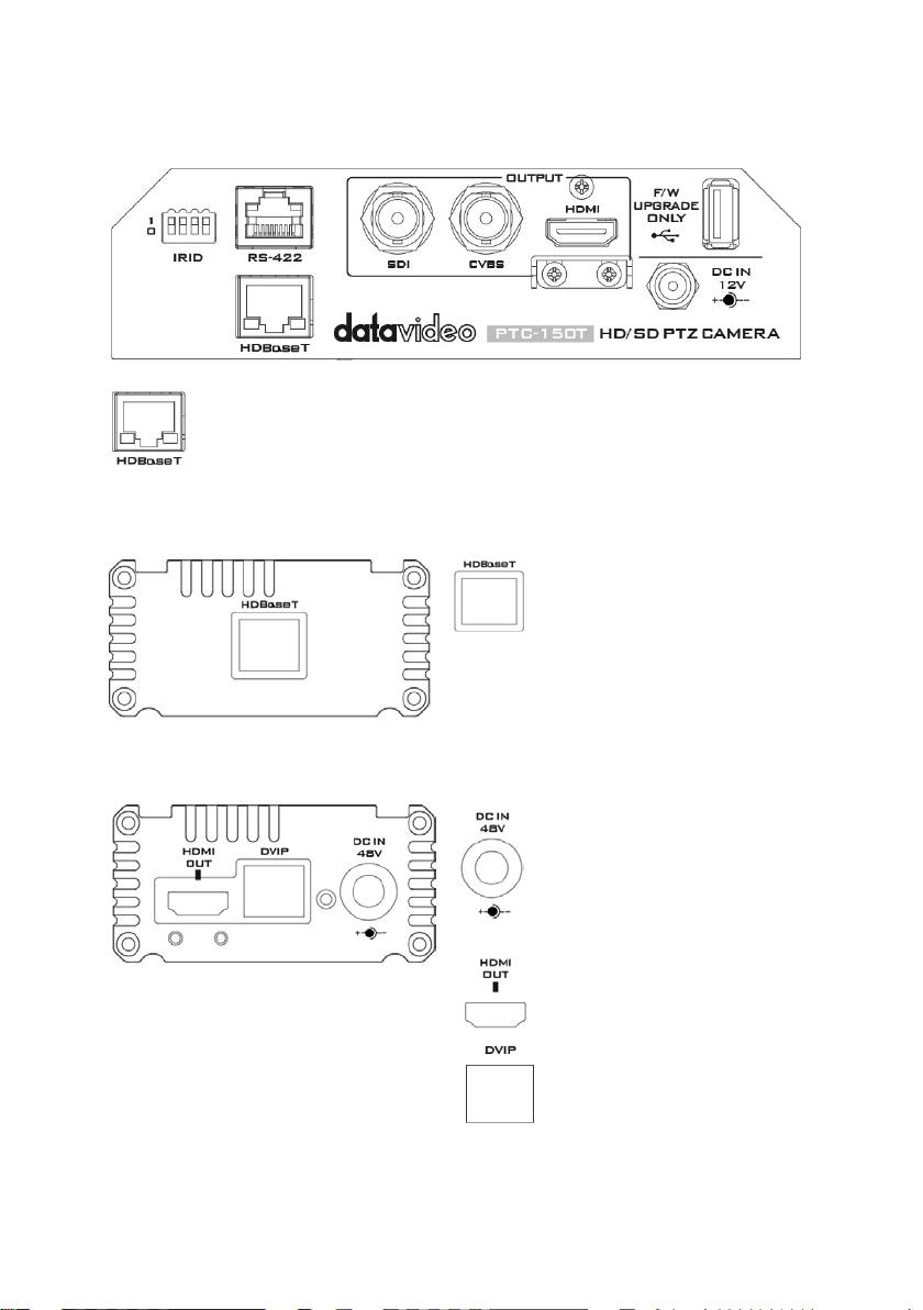
4. Connections
HDBaseT
HDBaseT
DC In Socket
HDMI OUT
DVIP Communication Port
4.1 Camera Rear Control Panel
Port for connection to the PTC-150T Receiver Box HD-Base-T Port using a CAT5e/6
Cable
4.2 Receiver Box Front Panel
Port for connection to the PTC150T Camera HDBaseT Port using a
CAT5e/6 Cable
4.3 Receiver Box Rear Panel
Warning: Please do not plug the 48V power adapter into the PTC-150T Camera DC-IN Socket.
Connects the supplied 48V PSU to
this socket. The connection can
be secured by screwing the outer
fastening ring of the DC In plug to
the socket.
Connection to Monitor Display
8
Page 9
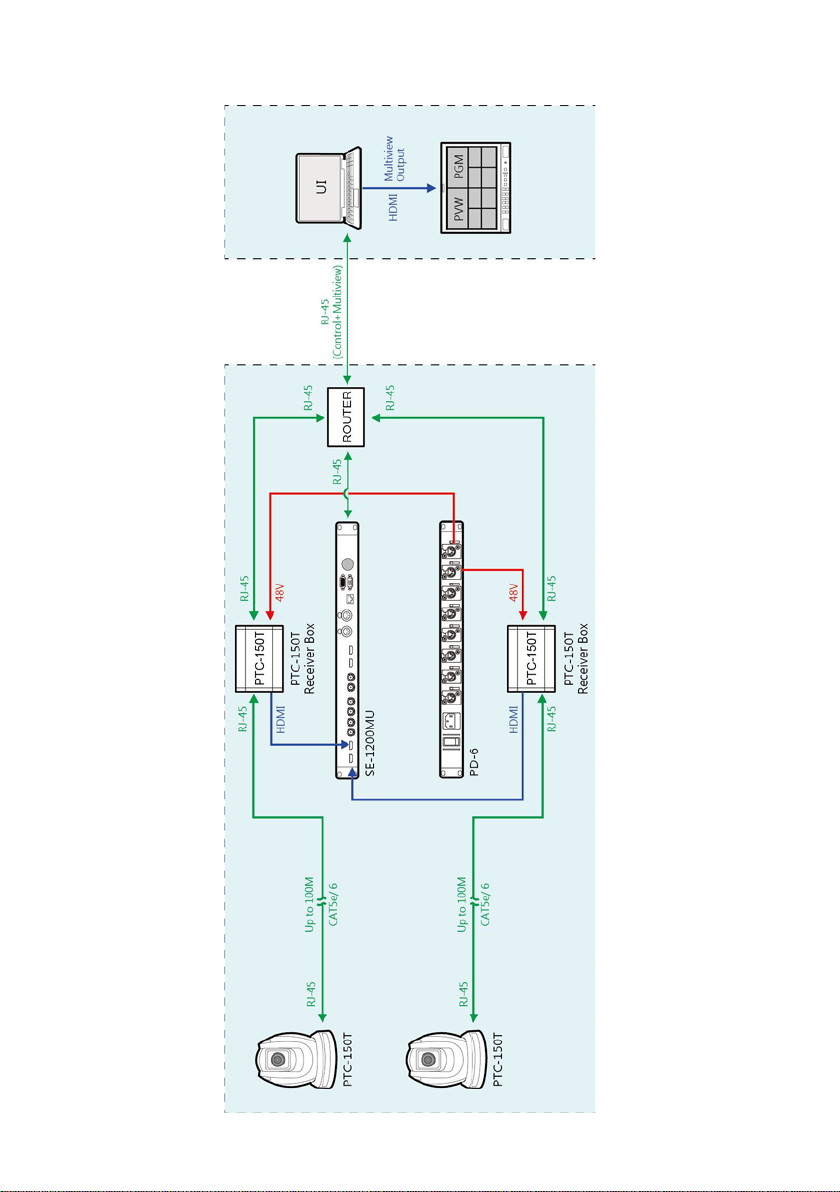
5. System Diagram
9
Page 10
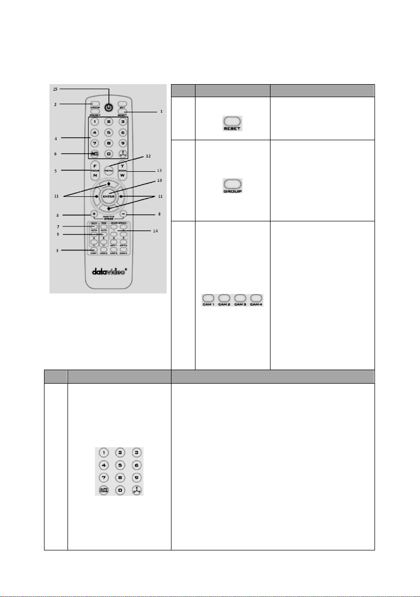
6. Remote Control and On-Screen Menu
No
Item
Description
No
Item Description
Various combinations of settings (position, zoom, focus,
Press any of the POSITION buttons 1~8 and then press
6.1 Remote Control Functions
gain control and iris control) can be saved to presets.
Adjust Preset Point
Position Setting
4
Adjust position, zoom, focus, gain control and iris of the
camera.
Set up Preset Point
Press any of the POSITION buttons 1~50 and then press
SET button.
Recall saved setting
Press any of the POSITION buttons 1~50 and then press
PRESET button.
Set up Group Scan mode
1
2
3
Reset
Group
Camera Select
Press RESET button to
return the camera lens to
the front.
Use the No. bottom & the
group bottom to select the
group scan.
Press any of the No. buttons
1~8 and then press GROUP
button.
Select CAM1-CAM4 in a
multi-camera environment
Assign an ID number to the
camera intended for
operation by adjusting the
IRID (SW2) switch located at
the rear of the camera
Press CAMERA SELECT (CAM
1~ CAM4) buttons
corresponding to the
numbers set previously to
navigate between four
cameras
10
Page 11
GROUP button.
Press number 0 and then press PRESET button.
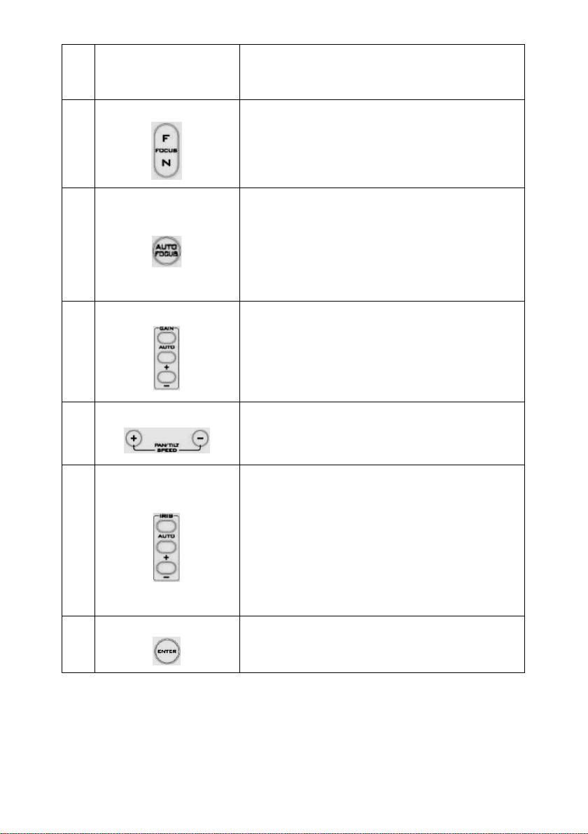
Return Camera Lens back to Front
Focus Setup
Manually focus camera lens on a subject
5
Auto Focus Control
6
Press either (F) FAR button or (N) NEAR button to manually
focus the camera lens onto the subject.
Automatically focus camera lens on a subject
Press A/ FOCUS button. Camera lens will be automatically
focused on the subject such that it is positioned at the
center of the screen.
Exit Sub-Menu Option
Press A/ FOCUS button to exit sub-menu option
10
Gain Control
7
P/T Speed
8
Auto Iris Control
9
ENTER
Adjust Brightness
Press GAIN+ button to increase the brightness or GAINbutton to decrease the brightness of the environment.
To cancel the function or return to default setup, press A/
GAIN button.
Adjust Pan/ Tilt Speed
Press SPEED + / - button to switch to different speed
(up/down)
Make the subject appear brighter
Adjust the iris opening (aperture), to control the amount of
light coming through the lens (i.e. the "exposure"). Press
IRIS+ button to enlarge the iris opening to allow more light
to come in so that the subject appears brighter and press
IRIS- button to shrink the iris opening to allow less light to
come in so that the subject appears less bright.
To cancel the function or return to default setup, press
A/IRIS button.
ENTER
Menu ENTER key
11
Page 12
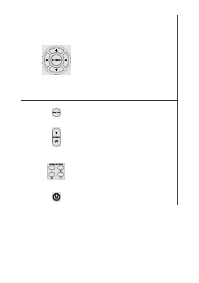
11
Direction Arrows
Change camera direction
Press arrow buttons to change the direction of the camera
head
Stop Preset Point Auto Scan mode
Press any of the DIRECTION buttons
Select Menu Option
Press UP or DOWN button to select the menu option
Adjust P/T Speed
Press UP or DOWN button to adjust the PAN/TILT Speed
Enter Sub-Menu Option
Press ENTER button to enter sub- menu option
Adjust Setup Value
Press LEFT or RIGHT button to adjust the value
Enter / Exit Camera Menu
12
Zoom In / Out Buttons
13
Zoom Speed Button
(4 speed selection)
14
Power Button
15
Enter or Exit Camera Menu Option
Zoom
Press either (T) TELE button to zoom in on the subject such
that it appears to be close to the camera or (W) WIDE
button to zoom out from the subject such that it appears
to be far away from the camera.
Adjust Zoom In/Out Speed
Press this button to switch to different speed (The
Highest~ The Lowest)
Switch Remote Controller ON/OFF
12
Page 13

6.2 On-Screen Menu
Main Options
Camera Set
(Normal)
Memory
Video
Output
Remote
Control
System
Camera Set
(Advance)
Reset
P/T/Z
Escape
1. Camera
Name
1. Preset
Position
1. Selection
Way
1. PAN/TILT
Reverse
1. Camera
Name
Reset
P/T/Z
2. Video
Mode
2. Remote
Source
2. Set
Motor
3. White
Balance
3. Set RS422
3. Tally
Light
3. White
Balance
4. Reset
All
5. Update
Software
6. PTZ
output
7. Fog
Correction
10. Pedestal
Effect
11. Backlight
Correct
12. Day/Night
Mode
14. Gamma
Mode
On-Screen MENU
On-Screen Menu allows the user to change various camera settings such as shooting conditions
and the system setup. Press [Menu] on the remote control to enter the on-screen menu as
shown below.
1: Camera Set (Normal)
2: Memory
3: Video Output
4: Remote Control
5: System
6: Camera Set (Advance)
7: Reset P/T/Z
8: Escape
The following table lists all the sub-options of the options on the main menu.
1. Display
2. Mirror 2.Group-1
3. Group-2 3. CV Mode
4. Focus 4. Group-3 4. Pattern 4. Set DVIP
5. Iris 5. Group-4 5. Escape 5. Set IR
6. AGC 6. Group-5
7. Escape 7. Group-6 7. Escape
8. Group-7 8. Aperture
9. Group-8 9. Vivid Effect
Sub-Options
10. Escape
13. Shutter
15. WD Mode
16. Escape
INFO.
6. Escape 6. AGC
2. Mirror
4. Focus
5. Iris
13
Page 14

Details of all options in the on-screen menu are listed in the table below.
First Level
Main Options
Second Level
Sub-Options
Third Level
Parameters
Fourth Level
Parameters
Sub-Option
Descriptions
LOWER LEFT
UPPER RIGHT
H+V
V
H
OFF
AWB(AUTO)
AWC (ONE PUSH)
MWB (MANUAL)
3200K (INDOOR)
6500K (OUTDOOR)
4200K (FLUO)
OFF SMART1/2/3
AUTO MANUAL
LOW
NORMAL
AUTO IRIS
MANUAL
F1.6 F2.0 F2.4 F2.8 F3.4
F4
F4.8 F5.6 F6.8 F8 F9.6 F11 F14
CLOSE
OFF
ON
0 dB ~ GAIN
LIMIT
GAIN LIMIT
9 dB
NAME
DISPLAY SW ON/OFF
POSITION
ESCAPE
MODE
SMART ATW
MWB RED COMPONENT 0~128~255
MWB BLUE COMPONENT 0~128~255
ESCAPE
FOCUS MODE
AF SENSITIVITY
FOCUS SPEED 1~4
ESCAPE
IRIS MODE
1. Camera Set
(Normal)
1. Camera Name
2. Mirror
3. White
Balance
4. Focus
5. Iris
6. AGC DAY (COLOR) AGC
MANUAL IRIS LEVEL
ESCAPE
14
AGC MODE
MANUAL GAIN
Page 15

12 dB
15 dB
18 dB
21 dB
24 dB
27 dB
30 dB
33 dB
36 dB
39 dB
ESCAPE
OFF
0 1 2
3
4
5
P T Z
PRESET NO.
1~50
ITEM ON/OFF
ON/OFF
SPEED LIMIT
1~18
WAITING TIME
0~180
NEXT TIME
RETURN
GROUP – 1
GROUP – 2
GROUP – 3
GROUP – 4
GROUP – 5
GROUP – 6
GROUP – 7
GROUP – 8
PRESET NO.
1~50
ITEM ON/OFF
ON/OFF
SPEED LIMIT
1~18
WAITING TIME
0~180
NEXT TIME
RETURN
GROUP – 1
GROUP – 2
GROUP – 3
DNR (AT AGC ON)
ON
2. Memory
7. Escape
1. Preset
Position
2. Group – 1
DNR
ESCAPE
1-50
51 ESCAPE
1-16
17. ESCAPE
DNR LEVEL
ESCAPE
NEXT POSITION
ESCAPE
3. Group – 2 1-16
NEXT POSITION
15
Page 16

GROUP – 4
GROUP – 5
GROUP – 6
GROUP – 7
GROUP – 8
17. ESCAPE
PRESET NO.
1~50
ITEM ON/OFF
ON/OFF
SPEED LIMIT
1~18
WAITING TIME
0~180
NEXT TIME
RETURN
GROUP – 1
GROUP – 2
GROUP – 3
GROUP – 4
GROUP – 5
GROUP – 6
GROUP – 7
GROUP – 8
PRESET NO.
1~50
ITEM ON/OFF
ON/OFF
SPEED LIMIT
1~18
WAITING TIME
0~180
NEXT TIME
RETURN
GROUP – 1
GROUP – 2
GROUP – 3
GROUP – 4
GROUP – 5
GROUP – 6
GROUP – 7
GROUP – 8
PRESET NO.
1~50
ITEM ON/OFF
ON/OFF
SPEED LIMIT
1~18
WAITING TIME
0~180
NEXT TIME
RETURN
GROUP – 1
GROUP – 2
GROUP – 3
GROUP – 4
GROUP – 5
GROUP – 6
GROUP – 7
GROUP – 8
ESCAPE
4. Group – 3
5. Group – 4
1-16
NEXT POSITION
ESCAPE
17. ESCAPE
1-16
NEXT POSITION
ESCAPE
17. ESCAPE
6. Group – 5 1-16
NEXT POSITION
16
Page 17

17. ESCAPE
PRESET NO.
1~50
ITEM ON/OFF
ON/OFF
SPEED LIMIT
1~18
WAITING TIME
0~180
NEXT TIME
RETURN
GROUP – 1
GROUP – 2
GROUP – 3
GROUP – 4
GROUP – 5
GROUP – 6
GROUP – 7
GROUP – 8
PRESET NO.
1~50
ITEM ON/OFF
ON/OFF
SPEED LIMIT
1~18
WAITING TIME
0~180
NEXT TIME
RETURN
GROUP – 1
GROUP – 2
GROUP – 3
GROUP – 4
GROUP – 5
GROUP – 6
GROUP – 7
GROUP – 8
PRESET NO.
1~50
ITEM ON/OFF
ON/OFF
SPEED LIMIT
1~18
WAITING TIME
0~180
NEXT TIME
RETURN
GROUP – 1
GROUP – 2
GROUP – 3
GROUP – 4
GROUP – 5
GROUP – 6
GROUP – 7
GROUP – 8
ESCAPE
7. Group – 6
8. Group – 7
1-16
NEXT POSITION
ESCAPE
17. ESCAPE
1-16
NEXT POSITION
ESCAPE
17. ESCAPE
9. Group – 8
1-16
NEXT POSITION
ESCAPE
17. ESCAPE
17
Page 18

3. Video
BY MENU
BY SWITCH
1080i60
1080i50
720p60
720p50
1080p30
1080p25
1080p60
1080p50
16:9
4:3
OFF
COLOR BAR
OFF P T
P+T
RS-422, SW
bottom DIP switch ONLY)
BY MENU
BY SWITCH
CAMERA ID
1~7
9600
19200
38400 115200
ESCAPE
9600
19200 38400 57600
115200
ESCAPE
IR GROUP ID
DIP switch ONLY)
ESCAPE
6. PTZ INFO.
Output
PAN OSD
ON/OFF
TILT OSD
ON/OFF
ZOOM OSD
ON/OFF
ESCAPE
DEBUG IR OSD
ON/OFF
DEBUG CAM. OSD
ON/OFF
DEBUG RS-422 OSD
ON/OFF
DEBUG DVIP OSD
ON/OFF
DEBUG M_CTL OSD
ON/OFF
DEBUG REG OSD
ON/OFF
DEBUG FRAME NO
ON/OFF
Output
10. Escape
1. Selection Way
2. Video Mode
3. CV Mode
4. Pattern
5. Escape
1. PAN/TILT
Reverse
4. Remote
Control
5. System
2. Remote
Source
3. Set RS-422
4. Set DVIP
5. Set IR
7. Escape
1. Display
(Configurable using
CAMERA ID MODE
RS-422 BAUD RATE
DVIP BAUD RATE
(Configurable using rear
ON/OFF
P/T/Z OSD
DEBUG OSD
CAM1~4
18
Page 19

PWR ON CAM TEST
ON/OFF
ESCAPE
2. Set Motor
LOW
+1~+5
LOW +1~+5
+5.4 +4.5 +3.6 +2.7
+1.8
+0.9 0.0 -0.9 -1.8 -2.7
-3.6 -4.5
-5.4
+6.3 +5.4
+4.5 +3.6 +2.7 +1.8 +0.9
0.0
-0.9 -1.8 -2.7 -3.6 -4.5
-5.4 -6.3
RED/GREEN
GREEN
RED
OFF
4. Reset All
YES/NO
SW VERSION
ESCAPE
MB CPU
V01.17i
MB FPGA
V017
MCTL CPU
V00.42
UPDATE ALL
YES/NO
ESCAPE
UPPER LEFT
LOWER LEFT
UPPER RIGHT
LOWER RIGHT
PAN torque ADJ
TILT torque ADJ
PAN offset ADJ
TILT offset ADJ
ESCAPE
6. Camera Set
(ADVANCE)
3. Tally Light
5. Update
Software
6. Escape
1. Camera Name
NAME
DISPLAY SW ON/OFF
POSITION
ESCAPE
19
Page 20

2. Mirror
H+V V
H
OFF
AWB (AUTO)
AWC (ONE PUSH)
MWB (MANUAL)
3200K (INDOOR)
6500K (OUTDOOR)
4200K (FLUO)
SMART ATW
mode)
OFF
AUTO
MANUAL
LOW NORMAL
1
2 3 4
AUTO
MANUAL
F1.6 F2.0
F2.4
F2.8 F3.4 F4 F4.8
F5.6
F6.8 F8
F9.6
F11 F14 CLOSE
0dB~GAIN
LIMIT
9 dB
12 dB
15 dB
18 dB
21 dB
24 dB
27 dB
30 dB
3. White
Balance
MODE
(Enabled in AWB (AUTO)
MWB RED COMPONENT 0~128~255
MWB BLUE COMPONENT 0~128~255
ESCAPE
FOCUS MODE
AF SENSITIVITY
SMART1~3
4. Focus
5. Iris
6. AGC DAY (COLOR) AGC
FOCUS SPEED
ESCAPE
IRIS MODE
Manual IRIS LEVEL
ESCAPE
AGC MODE ON/OFF
MANUAL GAIN
GAIN LIMIT
20
Page 21

33 dB
36 dB
39 dB
ESCAPE
DNR(AT AGC ON)
OFF
0 1 2 3 4
5
10. Pedestal
Effect
OFF/ON
after AGC is turned on)
NORMAL
1/100 1/125 1/250 1/500 1/1000
STANDARD
MODE4 (WD OFF)
ON/OFF
after AGC is turned on)
7. Reset P/T/Z
DNR
DNR LEVEL
ESCAPE
7. Fog
Correction
8. Aperture 0~15
9. Vivid Effect 0~14
FOG CORRECTION OFF/ON
ESCAPE
0~14
ON
8. Escape
11. Backlight
Correction
12. Day/Night
Mode
13. Shutter
14. Gamma
Mode
15. WD Mode
16. Escape
Reset P/T/Z YES/NO
(This option is enabled
B/W
COLOR
SHUTTER SPEED
ESCAPE
MODE1 (WD OFF)
MODE2 (WD OFF)
MODE3 (WD OFF)
(This option is enabled
21
Page 22

7. Instruction for installation
7.1 Step 1 – DIP Switch Setting
Set the Mirror option to H+V mode.
7.2 Step 2 – One End of Mounting Wire
Attach the mounting wire to the junction box mounted on the ceiling by screwing one end of the
mounting wire into a screw hole in the junction box with a screw (not supplied) as shown in the
diagram below.
7.3 Step 3 – Ceiling Bracket (B)
• Again, as illustrated in the diagram below, screw a ceiling bracket (B) into the
junction box mounted on the ceiling.
• Make sure the screw holes of the ceiling bracket (B) are aligned with the holes on
the junction box.
22
Page 23

7.4 Step 4 – Ceiling Bracket (A) and Camera
• Screw ceiling bracket (A) into the bottom of the camera using three screws.
• Position the screws as shown in the diagram below
• Align the screw holes on the bottom of the camera with those in the ceiling
bracket.
• Insert the screws into the corresponding screw holes in the numbered order
• The other end of the mounting wire is screwed into the screw hole #3.
• Securely tighten all three screws
23
Page 24

24 25
Page 25

7.5 Step 5 – Mount Camera to Ceiling
Page 26

7.6 Step 6 – Screw to Secure Camera
Secure the camera by screwing three screws into the corresponding screw holes as shown in the
diagram below.
7.7 Step 7 – Cable Connection
Connect the cables to the connectors located on the rear of the camera.
26
Page 27

8. DIP Switch Settings
Setting
VISCA ID
(1,2,3) = (ON,OFF,OFF)
VISCA-ID 1
(1,2,3) = (OFF,ON ,OFF)
VISCA-ID 2
(1,2,3) = (ON ,ON ,OFF)
VISCA-ID 3
(1,2,3) = (OFF,OFF,ON)
VISCA-ID 4
(1,2,3) = (ON ,OFF,ON)
VISCA-ID 5
(1,2,3) = (OFF,ON ,ON)
VISCA-ID 6
(1,2,3) = (ON ,ON ,ON)
VISCA-ID 7
Setting
Remote Source
(4) = (ON/OFF)
DVIP/RS422
Setting
Resolution
(5,6,7) = (OFF,OFF,OFF)
1920x1080i60
(5,6,7) = (ON,OFF,OFF)
1920x1080i50
(5,6,7) = (OFF,ON,OFF)
1280x720p60
(5,6,7) = (ON,ON,OFF)
1280x720p50
(5,6,7) = (OFF,OFF,ON)
1920x1080p30
(5,6,7) = (ON,OFF,ON)
1920x1080p25
(5,6,7) = (OFF,ON,ON)
1920x1080p60
(5,6,7) = (ON,ON,ON)
1920x1080p50
Setting
Remote Source
ON = video mode selected by DIP switch only
OFF = video mode selected by menu
Setting
Function Descriptions
(1,2) = (OFF,OFF)
CAM1 (IR)
(1,2) = (ON,OFF)
CAM2 (IR)
(1,2) = (OFF,ON)
CAM3 (IR)
(1,2) = (ON,ON)
CAM4 (IR)
* Keep the switch (3,4)=(OFF,OFF)
8.1 RS-422
(8) = (ON/OFF)
8.2 IRID
27
Page 28

9. DVIP Control Protocol
[MAIN MENU]
1:
CAMERA SET (NORMAL)
2:
MEMORY
3:
VIDEO OUTPUT
4:
REMOTE CONTROL
5:
SYSTEM
6:
CAMERA SET (ADVANCE)
7:
RESET P/T/Z
8:
ESCAPE
[REMOTE CONTROL]
1:
PAN/TILT REVERSE: P+T
2:
REMOTE SOURCE: DVIP, SW
3:
SET RS422
4:
SET DVIP
5:
SET IR
6:
PTZ INFO. OUTPUT: OFF
7:
ESCAPE
9.1 DVIP Setup
DVIP is a user interface that allows the user to control multiple PTC-150 cameras remotely. The
DVIP setup procedure is outlined as follows:
1. Locate the DIP switch at the bottom of the PTC-150 camera
2. Set DIP Switch positions 1 and 4 to ON
3. Plug in the power cord into the PTC-150 and connect it to a monitor via the HDMI interface.
4. Open the main menu by pressing the menu button on the remote control and select option
4 “Remote Control”
5. Select “SET DVIP” to configure the DVIP port
28
Page 29

6. Set the DVIP baud rate to to 115200
[SET DVIP]
1:
DVIP BAUDRATE: 115200
2:
ESCAPE
7. Connect your PC and the PTC-150 to an Ethernet router, which should automatically assign
an IP to the PTC-150
8. On the PC, open the DVIP Configuration Tool by double clicking “DVIP_ConfigureTools.exe”.
The DVIP Configuration Tool can be obtained from the Datavideo local distributors.
9. After the DVIP Configuration Tool is opened, select your network interface card as the
Interface and click the “Search” button
29
Page 30

10. On the DVIP Device List, you will then be able to see the Device Name, MAC address and IP
address of the connected PTC-150.
11. After the network setting (True Static and DHCP) and the host name are configured, click the
“Apply” button
12. The user will be prompted if the setup is successful.
13. Reboot the PTC-150 to apply the new settings.
30
Page 31

9.2 DVIP Control Operation Guide
Byte (8 bits)
Descriptions
0
Packet Length High Byte
1
Packet Length Low Byte
2
Command_Data [0]
…
…
513
Command_Data [511]
Byte (8 bits)
Descriptions
0
Packet Length High Byte
1
Packet Length Low Byte
2
0x80 3 Command
4
Parameter 1
…
…
251
Parameter 248
Request TCP/IP information, include DHCP mode, DHCP Host name, IP address, Netmask, MAC
address, Gateway, Primary DNS, Secondary DNS
Command
0x00
Parameter 1
0x45
Parameter 2
0x54
Parameter 3
0x48
Parameter 4
0x5F
Parameter 5
0x52
Parameter 6
0x45
Parameter 7
0x51
9.2.1 Physical Layer
• Control Interface: Ethernet
• Communication Speed: 10/100Mbps
• Control Protocol: TCP/IP
9.2.2 General Connection Information
• By default, the DVIP is configured to operate in DHCP mode. User is allowed to re-
configure to static IP address.
• TCP/IP Control port numbers
TCP port: 5002
9.2.3 Packet Data
Control Command Packet (TCP)
Broadcast Packet
UDP port: 5002
Broadcast Command List – Request TCP/IP information
Command Issue to DVIP device
31
Page 32

Command Return from DVIP device
Length
Descriptions
1 Byte
Data Length High Byte
1 Byte
Data Length Low Byte
1 Byte
0x80
1 Byte
0x00
1 Byte
DHCP; 0: Disable; 1: Enable
16 Bytes
DHCP Host name (15 bytes max) + Null (0x00) terminated
6 Bytes
MAC Address
4 Bytes
IP Address
4 Bytes
Netmask
4 Bytes
Gateway
4 Bytes
Primary DNS address
4 Bytes
Secondary DNS address
Request DVIP Firmware Revision
Command
0x01
Parameter 1
DVIP MAC address [0]
Parameter 2
DVIP MAC address [1]
Parameter 3
DVIP MAC address [2]
Parameter 4
DVIP MAC address [3]
Parameter 5
DVIP MAC address [4]
Parameter 6
DVIP MAC address [5]
Parameter 7
0x46
Parameter 8
0x57
Parameter 9
0x56
Parameter 10
0x45
Parameter 11
0x52
Parameter 12
0x5F
Parameter 13
0x52
Parameter 14
0x45
Parameter 15
0x51
Length
Descriptions
1 Byte
0x00 (Data Length High Byte)
1 Byte
0x06 (Data Length Low Byte)
1 Byte
0x80
1 Byte
0x01
1 Byte
Firmware Revision Major Number
1 Byte
Firmware Revision Minor Number
Broadcast Command List – Request specific DVIP device firmware revision
Command Issue to DVIP device
Command Return from DVIP device
32
Page 33

Broadcast Command List – Set DHCP Mode
Set DHCP Mode
Command
0x02
Parameter 1
DVIP MAC address [0]
Parameter 2
DVIP MAC address [1]
Parameter 3
DVIP MAC address [2]
Parameter 4
DVIP MAC address [3]
Parameter 5
DVIP MAC address [4]
Parameter 6
DVIP MAC address [5]
Parameter 7
0x53
Parameter 8
0x45
Parameter 9
0x54
Parameter 10
0x5F
Parameter 11
0x44
Parameter 12
0x48
Parameter 13
0x43
Parameter 14
0x50
Parameter 15
0x4D
Parameter 16
0x4F
Parameter 17
0x44
Parameter 18
0x45
Parameter 19
0x00: Disable; 0x01: Enable
Length
Descriptions
1 Byte
0x00 (Data Length High Byte)
1 Byte
0x06 (Data Length Low Byte)
1 Byte
0x80
1 Byte
0x02
1 Byte
0x06 (ACK) or 0x15 (NACK)
Set IP Address
Command
0x03
Parameter 1
DVIP MAC address [0]
Parameter 2
DVIP MAC address [1]
Parameter 3
DVIP MAC address [2]
Parameter 4
DVIP MAC address [3]
Parameter 5
DVIP MAC address [4]
Parameter 6
DVIP MAC address [5]
Parameter 7
0x53
Parameter 8
0x45
Parameter 9
0x54
Parameter 10
0x5F
Parameter 11
0x49
Parameter 12
0x50
Parameter 13
0x41
Command Issue to DVIP device
Command Return from DVIP device
Broadcast Command List – Set IP Address
Command Issue to DVIP device
33
Page 34

Parameter 14
0x44
Parameter 15
0x52
Parameter 16
IP_Address [0]
Parameter 17
IP_Address [1]
Parameter 18
IP_Address [2]
Parameter 19
IP_Address [3]
Parameter 20
Gateway [0]
Parameter 21
Gateway [1]
Parameter 22
Gateway [2]
Parameter 23
Gateway [3]
Length
Descriptions
1 Byte
0x00 (Data Length High Byte)
1 Byte
0x06 (Data Length Low Byte)
1 Byte
0x80
1 Byte
0x03
1 Byte
0x06 (ACK) or 0x15 (NACK)
Reset to Factory Default
Command
0x04
Parameter 1
DVIP MAC address [0]
Parameter 2
DVIP MAC address [1]
Parameter 3
DVIP MAC address [2]
Parameter 4
DVIP MAC address [3]
Parameter 5
DVIP MAC address [4]
Parameter 6
DVIP MAC address [5]
Parameter 7
0x52
Parameter 8
0x45
Parameter 9
0x53
Parameter 10
0x45
Parameter 11
0x54
Length
Descriptions
1 Byte
0x00 (Data Length High Byte)
1 Byte
0x06 (Data Length Low Byte)
1 Byte
0x80
1 Byte
0x04
1 Byte
0x06 (ACK) or 0x15 (NACK)
Get Device Model Number
Command
0x05
Parameter 1
DVIP MAC address [0]
Parameter 2
DVIP MAC address [1]
Command Return from DVIP device
Broadcast Command List – Reset to Factory Default
Command Issue to DVIP device
Command Return from DVIP device
Broadcast Command List – Get Device Model Number
Command Issue to DVIP device
34
Page 35

Parameter 3
DVIP MAC address [2]
Parameter 4
DVIP MAC address [3]
Parameter 5
DVIP MAC address [4]
Parameter 6
DVIP MAC address [5]
Parameter 7
0x47
Parameter 8
0x45
Parameter 9
0x54
Parameter 10
0x5F
Parameter 11
0x4D
Parameter 12
0x4F
Parameter 13
0x44
Parameter 14
0x45
Parameter 15
0x4C
Parameter 16
0x5F
Parameter 17
0x4E
Parameter 18
0x41
Parameter 19
0x4D
Parameter 20
0x45
Length
Descriptions
1 Byte
0x00 (Data Length High Byte)
1 Byte
0x06 (Data Length Low Byte)
1 Byte
0x80
1 Byte
0x04
16 Bytes
Device Model Number is 16 Bytes maximum; use null padding (0x00) if it is
less than 16 bytes.
Byte (8 bits)
Descriptions
0
Packet Length High Byte
1
Packet Length Low Byte
2
0x81
3
Command
4
Parameter 1
… … 251
Parameter 248
Request TCP/IP information, include DHCP mode, DHCP Host name, IP address, Netmask, MAC
address, Gateway, Primary DNS, Secondary DNS
Command
0x00
Parameter 1
0x45
Parameter 2
0x54
Parameter 3
0x48
Parameter 4
0x5F
Parameter 5
0x52
Command Return from DVIP device
UDP Packet
UDP Command List – Request TCP/IP information
Command Issue to DVIP device
35
Page 36

Parameter 6
0x45
Parameter 7
0x51
Length
Descriptions
1 Byte
Data Length High Byte
1 Byte
Data Length Low Byte
1 Byte
0x80
1 Byte
0x00
1 Byte
DHCP; 0: Disable; 1: Enable
16 Bytes
DHCP Host name (15 bytes max) + Null (0x00) terminated
6 Bytes
MAC Address
4 Bytes
IP Address
4 Bytes
Netmask
4 Bytes
Gateway
4 Bytes
Primary DNS address
4 Bytes
Secondary DNS address
Request DVIP Firmware Revision
Command
0x01
Parameter 1
0x46
Parameter 2
0x57
Parameter 3
0x56
Parameter 4
0x45
Parameter 5
0x52
Parameter 6
0x5F
Parameter 7
0x52
Parameter 8
0x45
Parameter 9
0x51
Length
Descriptions
1 Byte
0x00 (Data Length High Byte)
1 Byte
0x06 (Data Length Low Byte)
1 Byte
0x80
1 Byte
0x01
1 Byte
Firmware Revision Major Number
1 Byte
Firmware Revision Minor Number
Set DHCP Mode
Command
0x02
Parameter 1
0x53
Parameter 2
0x45
Parameter 3
0x54
Command Return from DVIP device
UDP Command List – Request specific DVIP device firmware revision
Command Issue to DVIP device
Command Return from DVIP device
UDP Command List – Set DHCP Mode
Command Issue to DVIP device
36
Page 37

Parameter 4
0x5F
Parameter 5
0x44
Parameter 6
0x48
Parameter 7
0x43
Parameter 8
0x50
Parameter 9
0x4D
Parameter 10
0x4F
Parameter 11
0x44
Parameter 12
0x45
Parameter 13
0x00: Disable; 0x01: Enable
Length
Descriptions
1 Byte
0x00 (Data Length High Byte)
1 Byte
0x06 (Data Length Low Byte)
1 Byte
0x81
1 Byte
0x02
1 Byte
0x06 (ACK) or 0x15 (NACK)
Set IP Address
Command
0x03
Parameter 1
0x53
Parameter 2
0x45
Parameter 3
0x54
Parameter 4
0x5F
Parameter 5
0x49
Parameter 6
0x50
Parameter 7
0x41
Parameter 8
0x44
Parameter 9
0x52
Parameter 10
IP_Address [0]
Parameter 11
IP_Address [1]
Parameter 12
IP_Address [2]
Parameter 13
IP_Address [3]
Parameter 14
Gateway [0]
Parameter 15
Gateway [1]
Parameter 16
Gateway [2]
Parameter 17
Gateway [3]
Length
Descriptions
1 Byte
0x00 (Data Length High Byte)
1 Byte
0x05 (Data Length Low Byte)
1 Byte
0x81
1 Byte
0x03
1 Byte
0x06 (ACK) or 0x15 (NACK)
Command Return from DVIP device
UDP Command List – Set IP Address & Gateway Address
Command Issue to DVIP device
Command Return from DVIP device
37
Page 38

Reset to Factory Default
Command
0x04
Parameter 1
0x52
Parameter 2
0x45
Parameter 3
0x53
Parameter 4
0x45
Parameter 5
0x54
Length
Descriptions
1 Byte
0x00 (Data Length High Byte)
1 Byte
0x06 (Data Length Low Byte)
1 Byte
0x81
1 Byte
0x04
1 Byte
0x06 (ACK) or 0x15 (NACK)
Set DHCP Host Name
Command
0x09
Parameter 1
0x53
Parameter 2
0x45
Parameter 3
0x54
Parameter 4
0x5F
Parameter 5
0x44
Parameter 6
0x48
Parameter 7
0x43
Parameter 8
0x50
Parameter 9
0x4E
Parameter 10
0x41
Parameter 11
0x4D
Parameter 12
0x45
Parameter 13…
Name (ASCII), 15 bytes Max.
Parameter
Null (0x00) terminated
Length
Descriptions
1 Byte
0x00 (Data Length High Byte)
1 Byte
0x05 (Data Length Low Byte)
1 Byte
0x81
1 Byte
0x09
1 Byte
0x06 (ACK) or 0x15 (NACK)
UDP Command List – Reset to Factory Default
Command Issue to DVIP device
Command Return from DVIP device
UDP Command List – Set DHCP Host Name
Command Issue to DVIP device
Command Return from DVIP device
38
Page 39

UDP Command List – Set Netmask
Set Netmask
Command
0x0B
Parameter 1
0x53
Parameter 2
0x45
Parameter 3
0x54
Parameter 4
0x5F
Parameter 5
0x4E
Parameter 6
0x45
Parameter 7
0x54
Parameter 8
0x4D
Parameter 9
0x41
Parameter 10
0x53
Parameter 11
0x4B
Parameter 12
Net_Mask [0]
Parameter 13
Net_Mask [1]
Parameter 14
Net_Mask [2]
Parameter 15
Net_Mask [3]
Length
Descriptions
1 Byte
0x00 (Data Length High Byte)
1 Byte
0x05 (Data Length Low Byte)
1 Byte
0x81
1 Byte
0x0B
1 Byte
0x06 (ACK) or 0x15 (NACK)
Set Gateway Address
Command
0x0C
Parameter 1
0x53
Parameter 2
0x45
Parameter 3
0x54
Parameter 4
0x5F
Parameter 5
0x47
Parameter 6
0x41
Parameter 7
0x54
Parameter 8
0x45
Parameter 9
0x57
Parameter 10
0x41
Parameter 11
0x59
Parameter 12
Gateway [0]
Parameter 13
Gateway [1]
Parameter 14
Gateway [2]
Parameter 15
Gateway [3]
Command Issue to DVIP device
Command Return from DVIP device
UDP Command List – Set Gateway Address
Command Issue to DVIP device
39
Page 40

Command Return from DVIP device
Length
Descriptions
1 Byte
0x00 (Data Length High Byte)
1 Byte
0x05 (Data Length Low Byte)
1 Byte
0x81
1 Byte
0x0C
1 Byte
0x06 (ACK) or 0x15 (NACK)
Set Gateway Address
Command
0x0D
Parameter 1
0x53
Parameter 2
0x45
Parameter 3
0x54
Parameter 4
0x5F
Parameter 5
0x50
Parameter 6
0x52
Parameter 7
0x49
Parameter 8
0x44
Parameter 9
0x4E
Parameter 10
0x53
Parameter 11
Primary_DNS_IP [0]
Parameter 12
Primary_DNS_IP [1]
Parameter 13
Primary_DNS_IP [2]
Parameter 14
Primary_DNS_IP [3]
Length
Descriptions
1 Byte
0x00 (Data Length High Byte)
1 Byte
0x05 (Data Length Low Byte)
1 Byte
0x81
1 Byte
0x0D
1 Byte
0x06 (ACK) or 0x15 (NACK)
Set Gateway Address
Command
0x0E
Parameter 1
0x53
Parameter 2
0x45
Parameter 3
0x54
Parameter 4
0x5F
Parameter 5
0x53
Parameter 6
0x45
Parameter 7
0x43
Parameter 8
0x44
Parameter 9
0x4E
Parameter 10
0x53
UDP Command List – Set Primary DNS Address
Command Issue to DVIP device
Command Return from DVIP device
UDP Command List – Set Secondary DNS Address
Command Issue to DVIP device
40
Page 41

Parameter 11
Secondary_DNS_IP [0]
Parameter 12
Secondary _DNS_IP [1]
Parameter 13
Secondary _DNS_IP [2]
Parameter 14
Secondary _DNS_IP [3]
Length
Descriptions
1 Byte
0x00 (Data Length High Byte)
1 Byte
0x05 (Data Length Low Byte)
1 Byte
0x81
1 Byte
0x0E
1 Byte
0x06 (ACK) or 0x15 (NACK)
Initial DVIP Configuration
Command
0x0F
Parameter 1
0x49
Parameter 2
0x4E
Parameter 3
0x49
Parameter 4
0x54
Parameter 5
0x5F
Parameter 6
0x45
Parameter 7
0x32
Parameter 8
0x50
Parameter 9
DHCP_Mode
Parameter 10
DHCP_Host_Name [0-14] (ASCII), 15 Bytes Max.
Parameter N
Null (0x00)
Parameter N+1
MAC_Address [0-3]
Parameter N+5
IP_Address [0-3]
Parameter N+9
Gateway_IP [0-3]
Parameter N+13
Net_Mask [0-3]
Parameter N+17
Primary_DNS_IP [0-3]
Parameter N+21
Secondary_DNS_IP [0-3]
Length
Descriptions
1 Byte
0x00 (Data Length High Byte)
1 Byte
0x05 (Data Length Low Byte)
1 Byte
0x81
1 Byte
0x0F
1 Byte
0x06 (ACK) or 0x15 (NACK)
Command Return from DVIP device
UDP Command List – Initial DVIP Configuration
Command Issue to DVIP device
Command Return from DVIP device
41
Page 42

10. RS-422 Control Protocol
NC
2 2
NC
RX-
3 3
TX-
TX-
4 4
RX-
TX+
5 5
RX+
RX+
6 6
TX+
NC
7 7
NC
NC
8 8
NC
GND
10.1 RS-422 PIN Descriptions
Camera
GND 1
Controller
1 GND
10.2 RS-422 Control Operation Guide
10.2.1 Overview of VISCA
In VISCA, the side outputting commands, for example, a computer is called the controller, while
the side receiving the commands, such as a PTC-150, is called the peripheral device. The PTC-150
serves as a peripheral device in VISCA. In VISCA, up to seven peripheral devices like the BRC300/P can be connected to one controller using communication conforming to the RS-232C/RS422 standard. The parameters of RS-232C/RS-422 are as follows.
• Communication speed: 38400 bps
• Data bits: 8
• Start bit: 1
• Stop bit: 1
• Non parity
Flow control using XON/XOFF and RTS/CTS, etc., is not supported.
The address of the controller is fixed at 0.
The addresses of peripheral devices are as follows.
42
Page 43

When the address of the controller is fixed at 0
VISCA Equipment
VISCA Controller
IN
OUT
The addresses of the peripheral devices are 1, 2, 3… in order, starting from the one nearest the
controller. The address of the peripheral device is set by sending address commands during the
initialization of the network.
When the address of the controller is fixed at 1 through 7
The addresses of the peripheral devices will be set on a pre-selected number. Within a single system,
the same number can be used only once. If an address-switch number other than 0 is to be used,
change the PTC-150 address switch to a different number beforehand.
Each VISCA device has a VISCA IN and VISCA OUT connector.
Set the DTR input (the S output of the controller) of VISCA IN to H when controlling VISCA
equipment from the controller.
Fig. 1 VISCA network configuration
10.2.2 VISCA Communication Specifications
10.2.2.1 VISCA Packet Structure
The basic unit of VISCA communication is called a packet (Fig. 2). The first byte of the packet is
called the header and comprises the sender’s and receiver’s addresses. For example, the header
of the packet sent to the PTC-150 assigned address 1 from the controller (address 0) is
hexadecimal 81H. The packet sent to the PTC-150 assigned address 2 is 82H. In the command list,
as the header is 8X, input the address of the PTC-150 at X. The header of the reply packet from
the PTC-150 assigned address 1 is 90H. The packet from the PTC-150 assigned address 2 is A0H.
Some of the commands for setting PTC-150 units can be sent to all devices at one time
(broadcast). In the case of broadcast, the header should be hexadecimal 88H.
When the terminator is FFH, it signifies the end of the packet.
43
Page 44

Fig. 2 Packet structure
Note
Fig. 2 shows the packet structure, while Fig. 3 shows the actual waveform. Data flow will take
place with the LSB first.
Fig. 3 Actual waveform for 1 byte
10.2.2.2 Timing Chart
As VISCA Command processing can only be carried out one time in a Vertical cycle, it takes the
maximum 1V cycle time for an ACK/Completion to be returned. If the Command
ACK/Completion communication time can be cut shorter than the 1V cycle time, then every 1V
cycle can receive a Command.
44
Page 45

Command Packet
Note
Inquiry
8X QQ RR … FF
QQ1) = Command/Inquiry
RR2) = category code
1)
QQ = 01 (Command), 09 (Inquiry)
RR = 00 (Interface), 04 (camera 1), 06 (Pan/Tilter)
Reply Packet
Note
Ack
X0 4Y FF
Y = socket number
Completion (Commands)
X0 5Y FF
Y = socket number
Completion (Inquiries)
X0 5Y … FF
Y = socket number
X = 9 to F: PTC-150 address + 8
Error Packet
Description
X0 6Y 01 FF
Message length error
X0 6Y 02 FF
Syntax error
X0 6Y 03 FF
Command buffer full
X0 6Y 04 FF
Command cancelled
X0 6Y 05 FF
No socket (to be cancelled)
X0 6Y 41 FF
Command not executable
X = 9 to F: PTC-150 address + 8, Y = socket number
Socket number = 1 (normal)
From this point, if 2 or more commands in a row are to be sent, wait for the first command (for
normal commands, an ACK or an error message, for query commands, an Inquiry Packet) to be
carried out before sending the next one.
10.2.2.3 Command and inquiry
• Command
Sends operational commands to the PTC-150.
• Inquiry
Used for inquiring about the current state of the PTC-150.
2)
X = 1 to 7: PTC-150 address
10.2.2.4 Responses for commands and inquiries
• ACK message
Returned by the PTC-150 when it receives a command. No ACK message is returned for inquiries.
• Completion message
Returned by the PTC-150 when execution of commands or inquiries is completed. In the case of
inquiry commands, it will contain reply data for the inquiry after the 3
ACK message is omitted, the socket number will contain a 0.
rd
byte of the packet. If the
• Error message
When a command or inquiry command could not be executed or failed, an error message is
returned.
45
Page 46

10.2.2.5 Socket number
Command Packet
Reply Packet
Note
IF_Clear
8X 01 00 01 FF
X0 50 FF
IF_Clear (broadcast)
88 01 00 01 FF
88 01 00 01 FF
X = 1 to 7: PTC-150 address (For inquiry packet)
X = 9 to F: PTC-150 address + 8 (For reply packet)
Command
Command
Message
Reply Message
Comments
General
81 01 04 38 02 FF
90 41 FF (ACK)+90 51 FF
Returns ACK when a
executed.
81 01 04 38 FF
90 60 02 FF
Accepted a command
parameters
81 01 04 38 02 FF
90 60 03 FF
There are two
accepted.
81 01 04 08 02 FF
90 61 41 FF
90 62 41 FF
Could not execute the
Inquiry
Command
81 09 04 38 FF
(Example)
90 50 02 FF (Completion)
ACK is not returned for
the inquiry command.
When command messages are sent to the PTC-150, it is normal to send the next command
message after waiting for the completion message or error message to return.
As the completion message or error message also has a socket number, it indicates which
command has ended.
The ACK message is not returned for these commands and inquiries, and only the completion
message of socket number 0 is returned.
10.2.3 VISCA Device Setting Command
Before starting control of the PTC-150, be sure to send the Address command and the IF_Clear
command using the broadcast function.
10.2.3.1 VISCA interface command
• IF_Clear
Clears the command buffers in the PTC-150 and cancels the command currently being executed.
10.2.4 VISCA Command/ACK Protocol
Command
(Example)
(Example)
(Example)
(Example)
(Completion)
90 42 FF 90 52 FF
(Syntax Error)
(Command Buffer Full)
(Command Not
Executable)
46
command has been
accepted, and
Completion when a
command has been
which is not supported
or a command lacking
commands currently
being executed, and the
command could not be
command in the
current mode.
Page 47

81 09 05 38 FF
(Example)
90 60 02 FF
Accepted an
command.
Address Set
88 30 01 FF
88 30 02 FF
Returned the device
address to +1.*
IF_Clear
(Broadcast)
88 01 00 01 FF
88 01 00 01 FF
Returned the same
command.
IF_Clear (For x)
8x 01 00 01 FF
z0 50 FF (Completion)
ACK is not returned for
this command.
Command
Command Message
Comments
ACK
z0 4y FF
(y: Socket No.)
Returned when the command is
accepted
Completion
z0 5y FF
(y: Socket No.)
Returned when the command has been
executed
Command
Command Messages
Comments
Syntax Error
z0 60 02 FF
Returned when the command format is
command parameters is accepted.
Command Buffer Full
z0 60 03 FF
Indicates that two sockets are already
when received.
No Socket
z0 6y 05 FF
Returned when no command is executed
number is specified.
Command Not
z0 6y 41 FF
Returned when a command cannot be
auto focus.
*When the address-switch is fixed at 0, the value x in 88 30 0x FF will be indeterminate.
Do not transmit the command (except Address Set, IF_Clear, CAM_POWER), when menu panel
shows on the screen. In that case, clear the menu panel first using CAM_Menu Command, and
then proceed.
(Syntax Error)
incompatible
10.2.5 VISCA Camera-Issued Messages
10.2.5.1 ACK/Completion Messages
z = Device address + 8
10.2.5.2 Error Messages
Executable
(y: Socket No.)
(y: Socket No.)
different or when a command with illegal
being used (executing two commands)
and the command could not be accepted
in a socket specified by the cancel
command, or when an invalid socket
executed due to current conditions. For
example, when commands controlling
the focus manually are received during
47
Page 48

10.2.6 PTC-150 Commands
Command Set
Command
Command Packet
Comments
AddressSet
Broadcast
88 30 01 FF
Address Set
IF_Clear
Broadcast
88 01 00 01 FF
I/F Clear
CAM_Power
On
8x 01 04 00 02 FF
Power On/Off
Off
8x 01 04 00 03 FF
CAM_ZOOM
Stop
8x 01 04 07 00 FF
Tele (Standard)
8x 01 04 07 02 FF
Wide (Standard)
8x 01 04 07 03 FF
Tele (Variable)
8x 01 04 07 2p FF
p (=0: Slow to
7:Fast)
Wide (Variable)
8x 01 04 07 3p FF
p (=0: Slow to
7:Fast)
Direct
8x 01 04 47 0p 0q 0r 0s FF
pqrs: Zoom
Position*
CAM_Focus
Stop
8x 01 04 08 00 FF
Far (Standard)
8x 01 04 08 02 FF
Near (Standard)
8x 01 04 08 03 FF
Direct
8x 01 04 48 0p 0q 0r 0s FF
pqrs: Focus
Position*
Auto Focus
8x 01 04 38 02 FF
AF ON/OFF
Manual Focus
8x 01 04 38 03 FF
One Push
Trigger
8x 01 04 18 01 FF
One Push AF
Trigger
CAM_WB
Auto
8x 01 04 35 00 FF
Normal Auto
Indoor
8x 01 04 35 01 FF
Indoor Mode
Outdoor
8x 01 04 35 02 FF
Outdoor Mode
One Push WB
8x 01 04 35 03 FF
One Push WB
Mode
Manual
8x 01 04 35 05 FF
Manual Control
Mode
One Push
Trigger
8x 01 04 10 05 FF
One Push WB
Trigger
CAM_RGain
Reset
8x 01 04 03 00 FF
Default R Gain
setting
Up
8x 01 04 03 02 FF
Down
8x 01 04 03 03 FF
Direct
8x 01 04 43 00 00 0p 0q FF
R Gain Direct pq
(=00 to FF)
CAM_BGain
Reset
8x 01 04 04 00 FF
Default B Gain
setting
Up
8x 01 04 04 02 FF
Down
8x 01 04 04 03 FF
Direct
8x 01 04 44 00 00 0p 0q FF
B Gain Direct pq
(=00 to FF)
CAM_AE
Full Auto
8x 01 04 39 00 FF
Automatic
exposure mode
Manual
8x 01 04 39 03 FF
Manual control
10.2.6.1 PTC-150 Command List
48
Page 49

mode
Shutter Priority
8x 01 04 39 0A FF
Shutter priority
automatic
exposure mode
Iris Priority
8x 01 04 39 0B FF
Iris priority
exposure mode
Bright
8x 01 04 39 0D FF
Bright mode
(Manual)
CAM_Shutter
Reset
8x 01 04 0A 00 FF
Default Shutter
setting
Up
8x 01 04 0A 02 FF
Down
8x 01 04 0A 03 FF
CAM_Iris
Reset
8x 01 04 0B 00 FF
Default Iris Setting
Up
8x 01 04 0B 02 FF
Down
8x 01 04 0B 03 FF
Direct
8x 01 04 4B 00 00 0p 0q FF
pq: Iris Position*
CAM_Gain
Reset
8x 01 04 0C 00 FF
Default Gain
setting
Up
8x 01 04 0C 02 FF
Down
8x 01 04 0C 03 FF
Direct
8x 01 04 4C 00 00 0p 0q FF
pq: Iris Position*
CAM_Backlight
On
8x 01 04 33 02 FF
Back Light ON/OFF
Off
8x 01 04 33 03 FF
PTZ_Position
Reset
8x 01 04 3F 00 0p FF
Memory Number p
(=0 to 50)
Set
8x 01 04 3F 01 0p FF
Memory Number p
(=0 to 50)
Recall
8x 01 04 3F 02 0p FF
Memory Number p
(=0 to 50)
CAM_Menu
On
8x 01 06 06 02 FF
Menu ON
Off
8x 01 06 06 03 FF
Menu OFF
Pan-tilt Drive
Up
8x 01 06 01 VV WW 03 01 FF
PanSpeed VV
Down
8x 01 06 01 VV WW 03 02 FF
Left
8x 01 06 01 VV WW 01 03 FF
Right
8x 01 06 01 VV WW 02 03 FF
UpLeft
8x 01 06 01 VV WW 01 01 FF
UpRight
8x 01 06 01 VV WW 02 01 FF
DownLeft
8x 01 06 01 VV WW 01 02 FF
DownRight
8x 01 06 01 VV WW 02 02 FF
Stop
8x 01 06 01 VV WW 03 03 FF
AbsolutePosition
8x 01 06 02 VV 00 0Y 0Y 0Y
Speed VV (=01:
ZZZZ: Tilt Position*
RelativePosition
8x 01 06 03 VV 00 0Y 0Y 0Y
Speed VV (=01:
ZZZZ: Tilt Position*
automatic
0Y 0Y 0Z 0Z 0Z 0Z FF
0Y 0Y 0Z 0Z 0Z 0Z FF
49
(=01:Slow to
18h:Fast)
TiltSpeed WW
(=01:Slow to
18h:Fast)
Slow to 18h:Fast)
YYYYY: Pan
Position*
Slow to 18h:Fast)
YYYYY: Pan
Position*
Page 50

Home
8x 01 06 04 FF
Reset
8x 01 06 05 FF
CAM_ImgFlip
On
8x 01 04 66 02 FF
Off
8x 01 04 66 03 FF
Cam_PanReverse
On
8x 01 7E 01 06 00 01 FF
Off
8x 01 7E 01 06 00 00 FF
Cam_TiltReverse
On
8x 01 7E 01 09 00 01 FF
Off
8x 01 7E 01 09 00 00 FF
Cmd_Tally
On
8x 01 7E 01 0A 00 02 FF
When Power is on,
return to off.
Off
8x 01 7E 01 0A 00 03 FF
Cmd_PT_M_Speed
Preset PT Speed
8x 01 7E 01 0B 0p 0q FF
p: Memory
18:fast)
*See the section under VISCA Command Setting Values
Inquiry Command
Command
Packet
Inquiry Packet
Comments
CAM_PowerInq
8x 09 04 00 FF
y0 50 02 FF
On
y0 50 03 FF
Off (Standby)
CAM_ZoomPosInq
8x 09 04 47 FF
y0 50 0p 0q 0r 0s FF
pqrs: Zoom Position
CAM_FocusModeInq
8x 09 04 38 FF
y0 50 02 FF
Auto Focus
y0 50 03 FF
Manual Focus
CAM_FocusPosInq
8x 09 04 48 FF
y0 50 0p 0q 0r 0s FF
pqrs: Focus Position
CAM_WBModeInq
8x 09 04 35 FF
y0 50 00 FF
Auto
y0 50 01 FF
Indoor
y0 50 02 FF
Outdoor
y0 50 03 FF
One Push WB
y0 50 05 FF
Manual
CAM_RGainInq
8x 09 04 43 FF
y0 50 00 00 0p 0q FF
pq: R Gain
CAM_BGainInq
8x 09 04 44 FF
y0 50 00 00 0p 0q FF
pq: B Gain
CAM_AEModeInq
8x 09 04 39 FF
y0 50 00 FF
Full Auto
y0 50 03 FF
Manual
y0 50 0A FF
Shutter Priority
y0 50 0B FF
Iris Priority
CAM_ShutterPosInq
8x 09 04 4A FF
y0 50 00 00 0p 0q FF
pq: Shutter Position
CAM_IrisPosInq
8x 09 04 4B FF
y0 50 00 00 0p 0q FF
pq: Iris Position
CAM_GainPosInq
8x 09 04 4C FF
y0 50 00 00 0p 0q FF
pq: Gain Position
CAM_BackLightModeInq
8x 09 04 33 FF
y0 50 02 FF
On
y0 50 03 FF
Off
CAM_MemoryInq
8x 09 04 3F FF
y0 50 pp FF
pp: Memory number
for PTZ last operated*
CAM_MENUInq
8x 09 06 06 FF
y0 50 02 FF
On
y0 50 03 FF
Off
CAM_VersionInq
8x 09 00 02 FF
y0 50 00 01
mn pq rs tu vw FF
mnpq: Model Code
(04xx)
10.2.6.2 PTC-150 Inquiry Command List
number (=0 to 50)
q: Speed (=1 to
50
Page 51

rstu: ROM version
(02)
CAM_ImgFlipInq
8x 09 04 66 FF
y0 50 02 FF
On
y0 50 03 FF
Off
CAM_PanReverseInq
8x 09 7E 01 06
FF
y0 50 01 FF
On
y0 50 00 FF
Off
CAM_TiltReverseInq
8x 09 7E 01 09
FF
y0 50 01 FF
On
y0 50 00 FF
Off
PanTilt_Status
8x 09 06 10 FF
y0 50 pq rs FF
pqrs: PanTilt Status
PanTilt_Max_Speed
8x 09 06 11 FF
y0 50 pq rs FF
pq: Pan Max Speed,
rs: Tilt Max Speed
PanTilt_Position
8x 09 06 12 FF
y0 50 0p 0q 0r 0s 0t
0u 0v 0w 0x FF
pqrst: Pan Position
uvwx: Tilt Position
Tally
8x 09 7E 01 0A
FF
y0 50 02 FF
On
y0 50 03 FF
Off
PanTilt_Memory_Speed
8x 09 7E 01 0B
0p FF
y0 50 0q FF
p: Preset No. 0 - 50,
qq: Speed 1 - 18 (h)
*See the section under VISCA Command Setting Values
vw: Socket Number
51
Page 52

11. Firmware Update
1) Copy three image files, p150mcpu.bin, P150FPGA.bin and p150mctl.bin, into the root
directory of a USB hard drive (<16 GB) and insert it into the USB port of PTC-150 (You may
also use USB extension cord).
2) Open the operation menu of IR remote controller (select from CAM 1-4; default is CAM1)
3) Main Menu
=> 5: SYSYEM
=> 4: UPDATE SOFTWARE
=> 5: UPDATE ALL
=>YES
=> ENTER
4) Wait for another five minutes until the following lines appear on the screen
- Updated Mot-BD=>OK.
- Updated FPGA =>OK.
- Updated MCPU =>OK
The OSD will flash “Write OK/Power ON Again” alternately; it takes approximately 5-7
minutes to complete the update.
5) Turn off the device by unplugging the power cord and plug the power cord back into the
socket to turn on the device again.
6) FW Update is complete.
52
Page 53

12. Dimensions
Unit: mm
53
Page 54

54
Page 55

13. Specifications
Effective Picture Elements
Gamma Control
Digital Noise Reductions
White Balance
Mirror
OFF / Horizontal / Vertical / H+V
Color Bar
On / Off (Full Bar)
Focus Mode
Video
Image Pickup Element 1/2.8” type progressive scan CMOS sensor
Approx. 2.14 Mega pixels
Resolution HD / FHD / SD (CVBS only)
HDMI & SDI: 1080/59.94p, 1080/59.94i, 1080/29.97p,
Signal System
S/N Ratio 50 dB
Min. Illumination
Electric Shutter 1/50 (1/60), 1/120 (1/100), 1/250, 1/500, 1/1000 sec
Iris Control Auto / Manual
On-Screen Display (OSD) English
AGC / Gain Control
Zoom Ratio 30x Optical Zoom
720/59.94p, 1080/50p, 1080/50i, 1080/25p, 720/50p
CVBS: 480i, 576i
Color : 0.4 lx (F1.6, 1/30 sec, 50IRE, Gain: High)
B/W : 0.03 lx (F1.6, 1/30 sec, 50IRE, Gain: High)
Off / Normal / Standard Mode 1-4
0 - 5
AWB / MWB / One push WB / Outdoor / Indoor / Fluorescent
Auto / Manual (0 to 39 step)
Max. Gain Limit (9 to 39 step)
Camera Title (OSD) ON / OFF
Day & Night (IR) Auto / Color / BW
Pan/Tilt Range Pan: 270° , Tilt: +90° to -20°
Pan/Tilt Speed
Initialization Time 30 sec
Coordinate Report P, T, Z (While Panning , Tilting and Zooming ) by frame
Lens Type 30x Optical Zoom
Focal Length
Angle of View (Horizontal) Approx. 63.7 degrees (WIDE END) / 2.3 degrees (TELE END)
Auto / Manual
Pan / Tilt / Zoom
Manual: 1~150°/Sec
Swing: 1~150°/Sec
Lens
F=4.3 mm (WIDE) to 129 mm (TELE)
F1.6 to F4.7
55
Page 56

Video Output
Protocol
VISCA / HDbaseT
Certifications
CE / FCC Class A
HDMI (V1.3) x 1
Video Output
Video Format Output 1 Vp-p / 75 Ohms
HD-SD-SDI x 1
CVBS x 1
HDBaseT x 1 to PTC-150T Receiver Box
Control
Remote Control RS-422 & HDBaseT by RJ-45 interface
F/W Update USB 2.0
IR Control One IR controller
Receiver Box
Protocol DVIP / HDBaseT
Video Out HDMI (V1.3) x 1
Power DC 48V (Please connect DC 48V to Receiver Box)
Control DVIP by RJ-45 interface
HDBaseT Distance Up to 100M by Cat.6 cable (RJ-45 interface)
Others
Moving Noise while Tilt <=25dB
Moving Noise while Pan <=25dB
Operating Temperature 0°C ~ 50°C
Storage Temperature - 10°C ~ 60°C
Operating Humidity: 10 % to 80 % (no condensation)
56
Page 57

14. Service and Support
57
 Loading...