

Datavideo PTC-120 Instruction Manual
1

2
Table of Contents
Warnings and Precautions ...................................................................... 5
Warranty ..................................................................................................... 6
Standard Warranty ........................................................................................ 6
Two Year Warranty ........................................................................................ 6
Disposal ...................................................................................................... 6
1. Product Overview ................................................................................. 7
2. Features .................................................................................................. 7
3. System Configuration .......................................................................... 8
3.1 Single Camera Connection ........................................................................ 8
IR Remote Control ..................................................................................... 8
SONY VISCA Compatible Controller ........................................................... 9
3.2 Multiple Cameras Cascade ..................................................................... 10
4. Location and Function of Parts ........................................................ 11
5. Remote Control and On-Screen Menu ............................................ 13
5.1 Remote Control Functions ...................................................................... 13
5.2 Descriptions of Major Functions ............................................................. 13
Switching between PTC-120 devices ....................................................... 13
Saving current lens position data ............................................................ 13
Clearing saved position data .................................................................... 14
Turning on backlight compensation function .......................................... 14
Adjusting lens shooting angle .................................................................. 14
Zoom in/out images ................................................................................. 14
Adjusting focal length .............................................................................. 14
Setting image mode ................................................................................. 14
Freezing images ....................................................................................... 14

3
Rotating image ......................................................................................... 14
Displaying current status ......................................................................... 14
Changing camera direction ...................................................................... 14
5.3 On-Screen Menu ..................................................................................... 15
Example 1 - Auto Focus Sensitivity Adjustment ...................................... 21
Example 2 - Auto Focus Speed Adjustment ............................................. 21
6. Instruction for installation ................................................................. 21
6.1 Preparation before Installation .............................................................. 21
6.2 Installation of PTC-120 on the desk ........................................................ 21
6.3 Installation of PTC-120 on the ceiling ..................................................... 22
7. DIP Switch ............................................................................................ 28
7.1 OUTPUT Switch ...................................................................................... 28
7.2 IR SELECT ................................................................................................ 29
7.3 Camera Address Selector ........................................................................ 29
7.4 System Switch ......................................................................................... 29
7.5 Service Switch ......................................................................................... 30
8. Component Video Output .................................................................. 31
8.1 DSub PIN Assignments............................................................................ 31
9. RS-232 PIN Assignments .................................................................. 32
9.1 PIN Descriptions ..................................................................................... 32
9.2 Wiring Diagrams .................................................................................... 32
10. RS-422 PIN Assignments ................................................................ 33
10.1 PIN Descriptions ................................................................................... 33
10.2 Physical Connection .............................................................................. 34
10.3 Wiring Diagrams .................................................................................. 35
11. VISCA Commands ............................................................................ 37

4
12. Firmware Update ............................................................................... 42
12.1 Requirements ....................................................................................... 42
12.2 DIP Switch Settings ............................................................................... 42
12.3 Connections .......................................................................................... 43
12.4 Firmware List ........................................................................................ 43
12.5 Firmware Update Mode ....................................................................... 43
12.6 DSP/CM/M3 Control Firmware Update ................................................ 44
13. Frequently-Asked Questions .......................................................... 46
14. Specification ...................................................................................... 49
15. SERVICE & SU PPO RT ...................................................................... 51
Disclaimer of Product and Services
The information offered in this instruction manual is intended as a guide only. At all times,
Datavideo Technologies will try to give correct, complete and suitable information. However,
Datavideo Technologies cannot exclude that some information in this manual, from time to time,
may not be correct or may be incomplete. This manual may contain typing errors, omissions or
incorrect information. Datavideo Technologies always recommend that you double check the
information in this document for accuracy before making any purchase decision or using the
product. Datavideo Technologies is not responsible for any omissions or errors, or for any
subsequent loss or damage caused by using the information contained within this manual. Further
advice on the content of this manual or on the product can be obtained by contacting your local
Datavideo Office or dealer.

5
Warnings and Precautions
1. Read all of these warnings and save them for later reference.
2. Follow all warnings and instructions marked on this unit.
3. Unplug this unit from the wall outlet before cleaning. Do not use liquid or
aerosol cleaners. Use a damp cloth for cleaning.
4. Do not use this unit in or near water.
5. Do not place this unit on an unstable cart, stand, or table. The unit may fall,
causing serious damage.
6. Slots and openings on the cabinet top, back, and bottom are provided for
ventilation. To ensure safe and reliable operation of this unit, and to protect it
from overheating, do not block or cover these openings. Do not place this unit
on a bed, sofa, rug, or similar surface, as the ventilation openings on the
bottom of the cabinet will be blocked. This unit should never be placed near or
over a heat register or radiator. This unit should not be placed in a built-in
installation unless proper ventilation is provided.
7. This product should only be operated from the type of power source indicated
on the marking label of the AC adapter. If you are not sure of the type of power
available, consult your Datavideo dealer or your local power company.
8. Do not allow anything to rest on the power cord. Do not locate this unit where
the power cord will be walked on, rolled over, or otherwise stressed.
9. If an extension cord must be used with this unit, make sure that the total of the
ampere ratings on the products plugged into the extension cord do not exceed
the extension cord’s rating.
10. Make sure that the total amperes of all the units that are plugged into a single
wall outlet do not exceed 15 amperes.
11. Never push objects of any kind into this unit through the cabinet ventilation
slots, as they may touch dangerous voltage points or short out parts that could
result in risk of fire or electric shock. Never spill liquid of any kind onto or into
this unit.
12. Except as specifically explained elsewhere in this manual, do not attempt to
service this product yourself. Opening or removing covers that are marked “Do
Not Remove” may expose you to dangerous voltage points or other risks, and
will void your warranty. Refer all service issues to qualified service personnel.
13. Unplug this product from the wall outlet and refer to qualified service
personnel under the following conditions:
a. When the power cord is damaged or frayed;
b. When liquid has spilled into the unit;
c. When the product has been exposed to rain or water;
d. When the product does not operate normally under normal operating
conditions. Adjust only those controls that are covered by the operating
instructions in this manual; improper adjustment of other controls may result in
damage to the unit and may often require extensive work by a qualified
technician to restore the unit to normal operation;
e. When the product has been dropped or the cabinet has been damaged;
f. When the product exhibits a distinct change in performance, indicating a
need for service.

6
Warranty
Standard Warranty
•
Datavideo equipment is guaranteed against any manufacturing defects for one
year from the date of purchase.
•
The original purchase invoice or other documentary evidence should be
supplied at the time of any request for repair under warranty.
•
Damage caused by accident, misuse, unauthorized repairs, sand, grit or water is
not covered by this warranty.
•
All mail or transportation costs including insurance are at the expense of the
owner.
•
All other claims of any nature are not covered.
•
Cables & batteries are not covered under warranty.
•
Warranty only valid within the country or region of purchase.
•
Your statutory rights are not affected.
Two Year W arran ty
•
All Datavideo products purchased after 01-Oct.-2008 qualify for a free one year
extension to the standard Warranty, providing the product is registered with
Datavideo within 30 days of purchase. For information on how to register
please visit www.datavideo.com or contact your local Datavideo office or
authorized Distributors
•
Certain parts with limited lifetime expectancy such as LCD Panels, DVD Drives,
Hard Drives are only covered for the first 10,000 hours, or 1 year (whichever
comes first).
Any second year warranty claims must be made to your local Datavideo office or one
of its authorized Distributors before the extended warranty expires.
Disposal
For EU Customers only - WEEE Marking
This symbol on the product indicates that it will not be treated
as household waste. It must be handed over to the applicable
take back scheme for the recycling of electrical and electronic
equipment. For more detailed information about the recycling
of this product, please contact your local Datavideo office.

7
1. Product Overview
The Datavideo PTC-120 HD/SD Video Camera is a PTZ camera that can be mounted on a wall,
ceiling, floor, or a tabletop, and comes with an IR remote control. The camera is equipped with
• 1/2.8 inch image sensor
• Full HD-1080p output resolution
• High dynamic image of up to 60 frames per second
• Superior 20x optical zoom lens
• Excellent white balance
Its exposure mode delivers a clear image even in a low light environment or under conditions of
extreme light and dark contrast in a conference room.
The camera covers a wide shooting angle and utilizes the high efficiency servo-controlled DC
motor to achieve instantaneous, quiet, and precise positioning, as well as smooth PTZ operations.
PTC-120 supports 3G-SDI, DVI, component, and Composite Video interfaces to allow four
simultaneous image outputs.
PTC-120 is compatible with all video equipment with up to 128 preset settings. A dedicated
remote control is available. PTC-120 delivers a continuous, clear, and vivid live image without any
distortions. It is ideally suited for lecture recording, video conferencing, and stage performance.
2. Features
• HD Resolution: 1/2.8" High Definition 2.0 M Pixels CMOS sensor
• 20x optical zoom; 12x digital zoom
• High definition formats supported:
- 1080p60/ 59.94/ 50/ 30/ 29.97/ 25
- 1080i60/ 59.94/ 50
- 720p60/ 59.94/ 50/ 30/ 29.97/ 25
- 480i/ 576i (CVBS)
• 240 times variable zoom ratio (20x optical zoom with 12x digital zoom)
• Maximum horizontal/vertical speed of rotation: 300 degrees/sec
• Delivers a fast response with an extremely clear image
• Video Output: Simultaneous 3G-SDI, DVI, Component and CVBS image outputs
• SONY VISCA Protocol Keyboard supported
8
3. System Configuration
The PTC-120 PTZ Color Video Camera can be set up in various system configurations. This section
describes how PTC-120 can be connected as a standalone device as well as cascade connection of
multiple cameras.
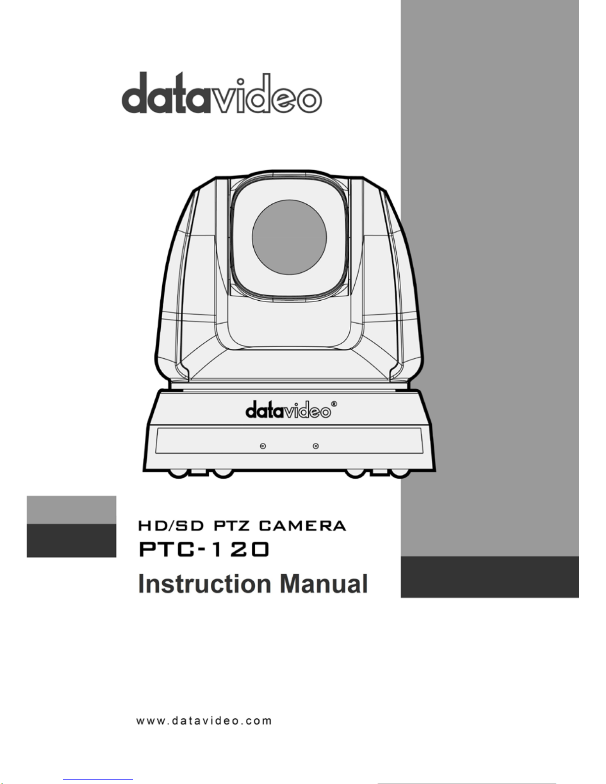
3.1 Single Camera Connection
IR Remote Control
This camera can be set up within a short distance by using the supplied IR remote control, see
section 5.1. In this way the camera can be used as a standalone device. The following video
output connections are available from the rear of the camera, 3G-SDI, Component, DVI and CVBS.
Below scenario diagrams show each of these connections in use with an appropriate cable and
monitor/TV.
PTC-120 to an HDTV or a computer
monitor (DVI) (Cable Optional)
PTC-120 to a TV (Composite Video)
(Cable Optional)
PTC-120 to a monitor (3G-SDI)
(Cable Optional)
PTC-120 to an HDTV or a TV
(Component) (Cable Optional)
9
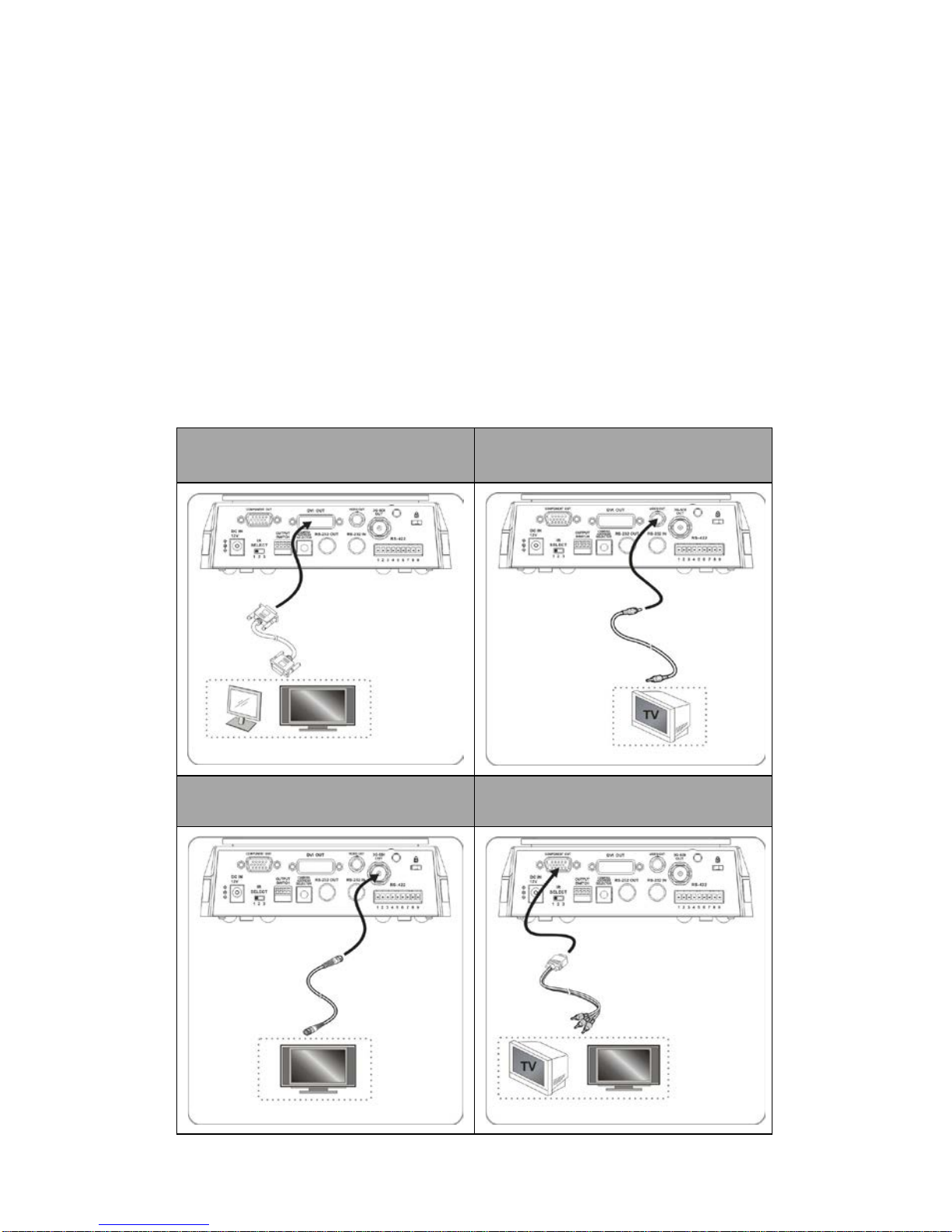
SONY VISCA Compatible Controller
In addition to the supplied IR remote control, the PTC-120 camera can also be
controlled remotely using a SONY VISCA compatible controller such as the Datavideo RMC-190
unit. This camera can be controlled over an RS-232C or RS-422 connection as shown in the
diagrams below. The camera video output is connected to the monitor via one of the four
available video interfaces.
RS-232 System Setup
RS-422 System Setup
10
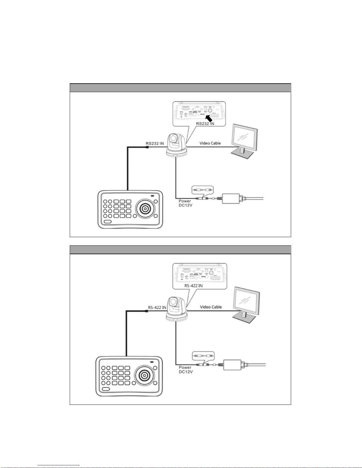
3.2 Multiple Cameras Cascade
The PTC-120 camera can also be used in an environment where multiple cameras are required.
With RS-232 INPUT/OUTPUT ports, the user is allowed to cascade up to seven cameras, which are
subsequently controlled by either a computer (Please download a utility program first from
http://www.serialporttool.com/PTZ.htm
in case you need to control the camera via a PC) or a
SONY VISCA compatible controller. RS-232C and RS-422 system setups for connection of multiple
cameras are illustrated in the respective diagrams below.
RS-232C Cascade Connection
RS-422 Cascade Connection
For wiring information, please see Section 11 for RS-232C and Section 12 for RS-
422.
However, the connection will be broken if one unit is powered off. In other words, the cameras
connected subsequent to the broken one will become uncontrollable by RMC-190. For example,
in the above diagram, if cameras #2 and #3 are defective or powered off, all camera connections
(4/5/6/7) after camera #3 will be cut off from the daisy chain and RMC-190 will not be able to
control them even if the cameras are still operable.
The cameras have to be at least in the standby mode for the entire daisy chain connection to stay
controllable by RMC-190. In the above example, if cameras #2 and #3 are in standby mode, the
user will still be able to control all cameras after camera #3 from RMC-190.
If the camera is powered off or defective, there will be no LED lighting in standby mode. The user
should check the LED lighting first if the daisy chain is found to be broken.
11
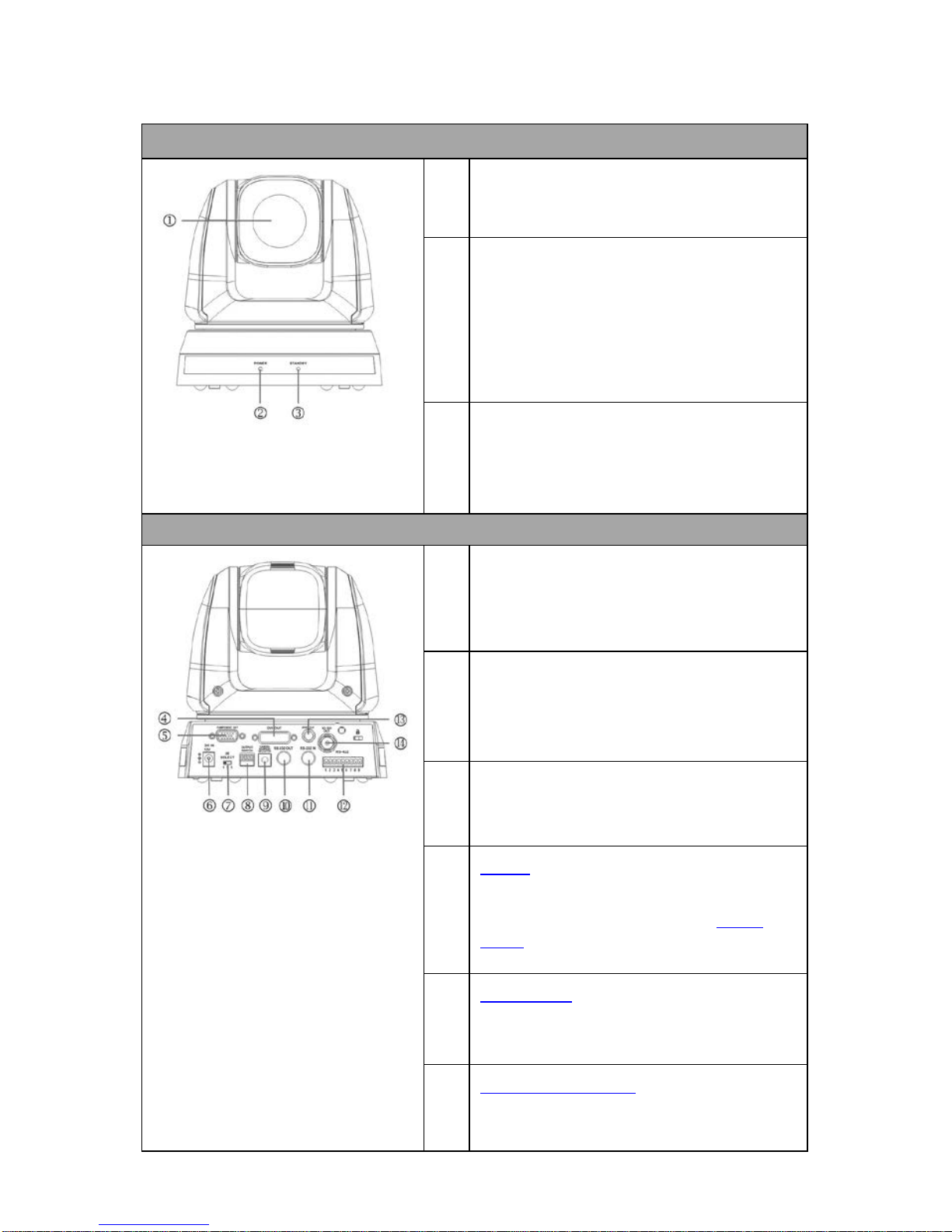
4. Location and Function of Parts
Front of Camera
1. Camera Lens
20x Optical Zoom; 12x Digital Zoom
2. Power LED Indicator
No Light: Power off
Green: In use
Flashing Green: Receiving signal from the remote
control; the indicator flashes every 0.5 second
3. Standby LED Indicator
Orange: Standby mode
No Light: Power on
Rear of Camera
4. DVI Video Output
Transfer of digital video content; A DVI to HDMI cable
can be used.
5. Component Video Output
Outputs camera images as analog component video
standards.
6. DC IN 12V Connector
Connect the supplied AC power adaptor.
7. IR Select (Section 9.2)
Assigns the camera an identification number when
you operate multiple cameras using the
Remote
Control (Section 5.1).
8. OUTPUT Switch (Section 9.1)
Set the output resolution.
9. Camera Address Selectors (Section 9.3)
Set the camera address.
12
10. RS-232C Output
Connection of multiple cameras
11. RS-232C Input
VISCA Control
(Section 13)
12. RS-422 I/O Connection
VISCA Control
(Section 13) and Connection of
multiple cameras
13. Composite VIDEO Output
Analog Video Transmission
14. 3G-SDI Output
Video Streaming
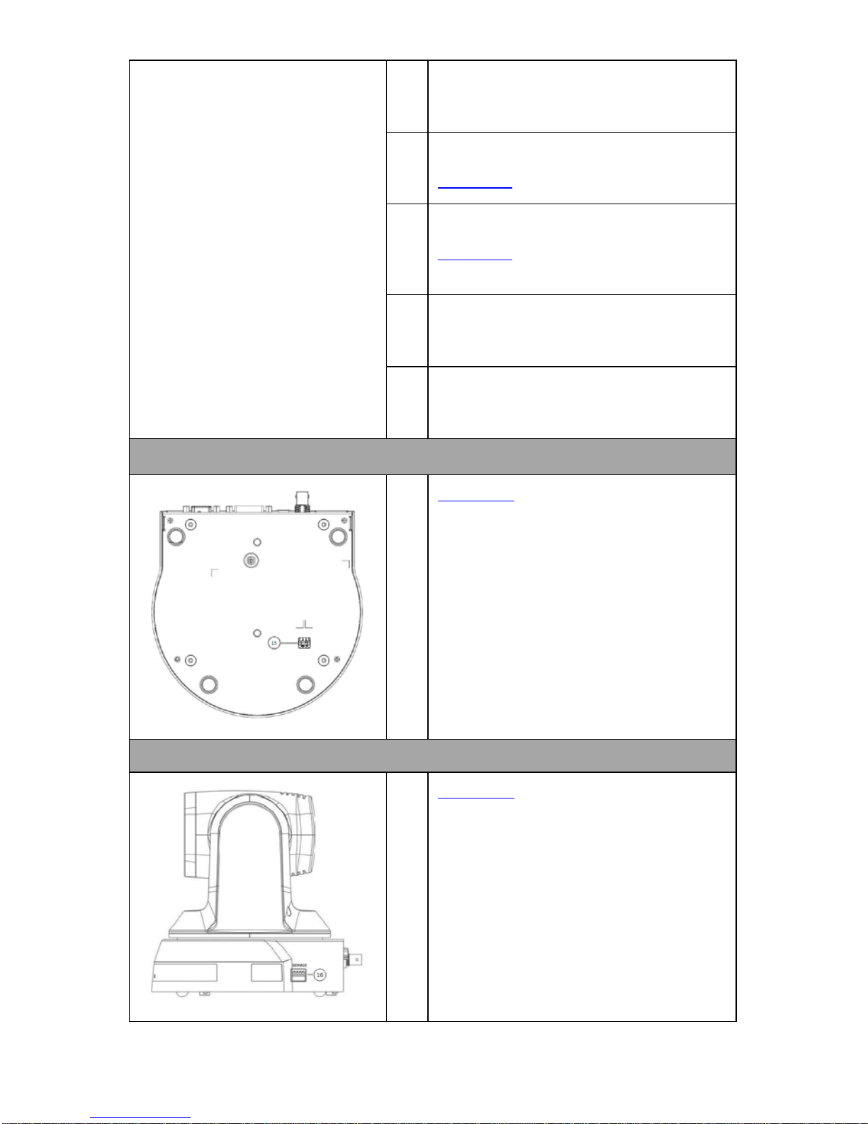
Bottom of Camera
15. System Switch (Section 9.4)
DIP 1 selects RS-232C or RS-422
DIP 2 turns ON/OFF IR Signal Output Switch
DIP 3 selects communication baud rate
DIP 4 is reserved
Side of Camera
16. Service Switch (Section 9.5)
Service switch is used to set the respective firmware
upgrades.
13
5. Remote Control and On-Screen Menu
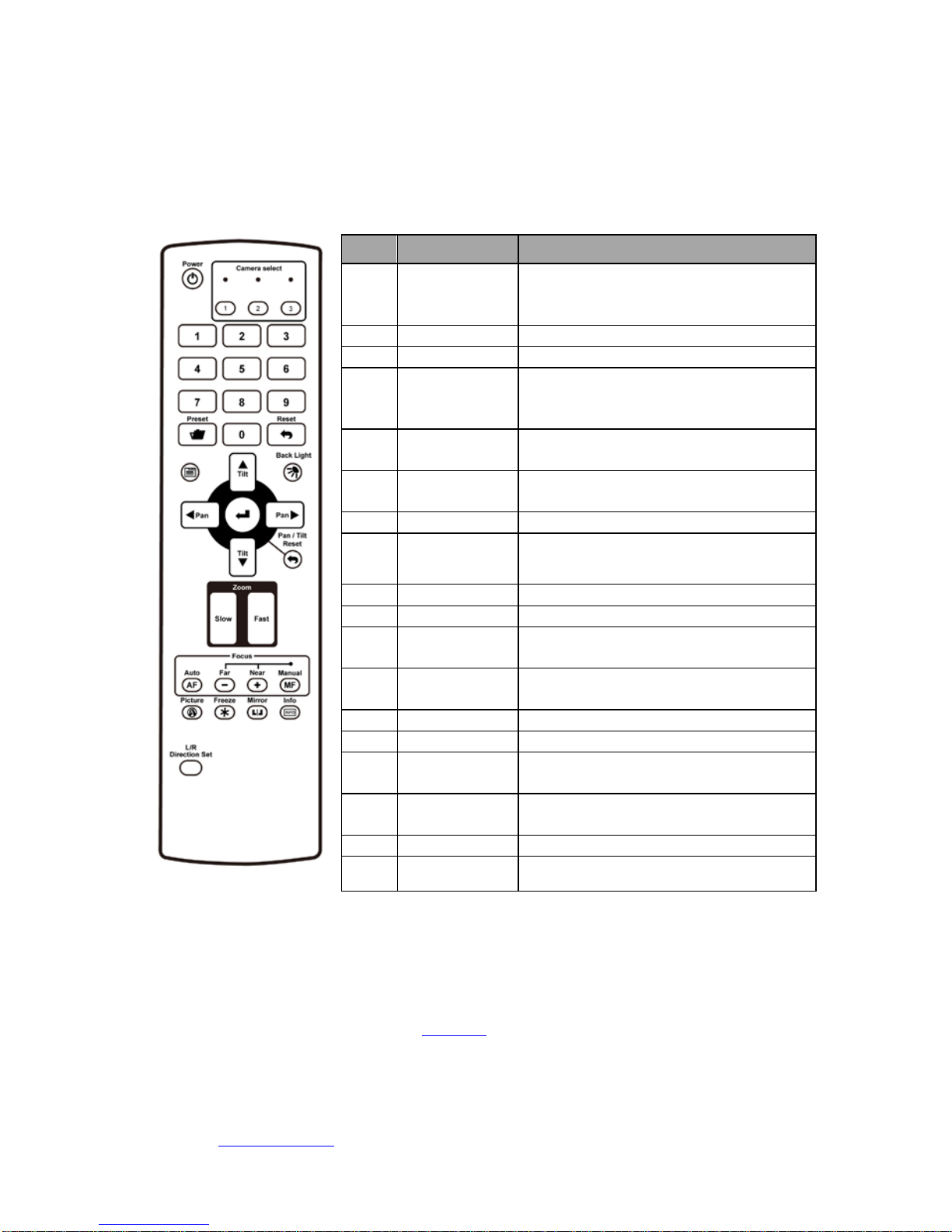
5.1 Remote Control Functions
Functions below are listed in alphabetical order.
No.
Item
Description
1
///
PAN-TILT Buttons
Press the arrow buttons to pan and tilt
the lens
2
Backlight
Turn on/off backlight compensation
3
Camera Select
Select PTC-120 Cameras 1-3
4
Focus – Far /
Near /
Manual
To adjust the focus manually, press the
MANUAL button and adjust the focus
with the FAR and NEAR buttons
5
Focus – Auto
Press the AUTO button to adjust the
focus automatically
6
Freeze
Press Freeze button to freeze the
current image on the display
7
Home – Enter
Go back to the main page/Execute
8
Info
Press Info button to display the current
status information
9
L/R Direction
Set L/R Direction/OFF/Normal
10
Menu
Display OSD menu
11
Mirror
Rotate the image
(Off/Mirror/Flip/Mirror+Flip)
12
Pan/Tilt Reset
Press the PAN/TILT Reset button to
return the lens to its original position
13
Picture
Switch image effect (OFF/Neg/B&W)
14
Power
Power Switch
15
Preset
Appoint an ID (0-9) to the current
position
16
Reset
Delete the current position data of the
appointed ID (0-9)
17
Zoom – Fast
Press fast to zoom quickly
18
Zoom – Slow
Press slow to zoom slowly
5.2 Descriptions of Major Functions
Switching between PTC-120 devices
Press [Camera 1 ~ 3] on the remote control to select the corresponding PTC-120 camera.
• Camera 1 ~ 3 is selected with IR SELECT
(Section 9.2).
Saving current lens position data
Press [Preset + ID] on the remote control to save the current position data.
• ID shall be a digit [0 ~ 9].
• VISCA Command (Section 13) can store up to 128 camera positions

14
Clearing saved position data
Press [Reset + ID] on the remote control to clear the given position data.
• ID shall be a digit [0 ~ 9].
• Use VISCA Command (Section 13) to clear the position data of [0~127]
Turning on backlight compensation function
Press [Back Light] on the remote control to turn on or turn off the back light
compensation.
Adjusting lens shooting angle
Press [ Tilt ] or [Tilt ] on the remote control to adjust the lens shooting angle
upward or downward.
Press [Pan ] or [Pan ] on the remote control to adjust the lens shooting angle to
right or left.
Press [Pan - Tilt Reset] on the remote control to reset the lens shooting angle to the
center point.
Zoom in/out images
Adjust image size
• Press [Fast +] on the remote control to zoom in images quickly.
• Press [Fast -] on the remote control to zoom out images quickly.
Fine-tune image size
• Press [Slow +] on the remote control to zoom in images slowly.
• Press [Slow -] on the remote control to zoom out images slowly.
Adjusting focal length
Auto tune
• Press [AF (Auto)] on the remote control to adjust the focal length automatically.
Manual focus
• Press [MF (Manual)] on the remote control to turn on the manual focal length
adjustment function.
• Press [- (Far)] or [+ (Near)] to adjust the focal length manually.
Setting image mode
Press [Picture] on the remote control to switch between [Off/Neg/B&W].
Freezing images
Press [Freeze] on the remote control to freeze the current image on the display.
Rotating image
Press [Mirror] on the remote control to switch between [Off/Mirror/Flip/Mirror + Flip].
Displaying current status
Press [Info] on the remote control to display the current status information.
Changing camera direction
Press [L/R Direction Set] on the remote control to switch between [L/R Direction / Off /
Normal].

15
5.3 On-Screen Menu
On-Screen Menu allows the user to change various camera settings such as shooting
conditions and the system setup. Press [Menu] on the remote control to enter the onscreen menu as shown below.
The following table lists all the sub-options of the options on the main menu.
Main
Options
Exposure
White
Balance
Picture
PAN/TILT
Zoom
D-Effect
AUTO
FOCUS
System Status
Sub-Options
Mode Mode
Picture
Effect
PAN/TILT
Limit
Mirror
AF
Sensitivity
Composite
Video
Exposure_C
omp
One Push
Trigger
Sharpness
PAN Right
Limit
AF Speed Video Type
Exposure_C
omp Level
2D NR
PAN Left
Limit
AF Frame Prompt
Spot Light 3D NR
TILT UP
Limit
IR Receive
Spot Light
Position
Image
Mode
TILT Down
Limit
Language
Shutter Pri
Image
Mode Load
D-Zoom
Limit
Control
Device
Manual
Gain
Saturation
Preset
Speed
Factory
Reset
Manual
Speed
Hue
Gain Limit Gamma
WDR Skin Tone
Brightness
Contrast
Black Level
On-Screen MENU
• Exposure
• White Balance
• Picture
• PAN/TILT Zoom
• D-Effect
• Auto Focus
• System
• Status

16
Details of all options in the on-screen menu are described in the table below. The bold
underlined values are defaults.
First Level
Main Options
Second Level
Sub-Options
Third Level
Parameters
Sub-Option
Descriptions
Exposure
Mode (Exposure
Mode)
1. Full Auto
2. Shutter Pri
3. Manual
4. White Board
FULL AUTO: The exposure is
adjusted automatically using
the sensitivity, electronic
shutter speed and iris.
Shutter Pri: Shutter Priority
mode. The exposure is
adjusted automatically using
the sensitivity and iris. Adjust
the electronic shutter speed
(SPEED) manually.
Manual: The sensitivity
(GAIN), electronic shutter
speed (SPEED) and iris (IRIS)
are adjusted manually.
White Board mode is turned
on when the background is a
white board in order to
automatically adjust the
brightness.
Exposure_Comp.
On/Off
ON: Enable exposure
compensation
OFF: Disable exposure
compensation
Exposure_Comp.
Level
-6~0~4
When exposure
compensation is enabled,
you can select the exposure
compensation level from -6 –
4.
Setting Exposure_Comp.Level
to 0 is equivalent to disabling
exposure compensation.
Spot Light On/Off
This function can be turned
on only when the mode is set
to Full Auto or Shutter Pri.
Spot Light
Position
X(0~8)Y(0~6)
The value can be adjusted
only after Spot Light is
enabled.
Shutter Pri
60/30
mode
50/25
mode
Shutter priority setting; fast
shutter results in a darker
image and slow shutter
results in a bright image.
1/10000
1/10000
1/5000
1/5000
 Loading...