

Page 1
xecom
XE1214B5
06-24-93
1200bps Component Modem
D e s c r i p t i o n
The XE1214B5 is a complete, self contained
1200/300 bps modem in small, component form. It
contains all circuitry necessary for a complete
modem, including an internal, FCC Registered,
Data Access Arrangement (DAA) for direct
connection to the telephone line, and a serial TTL
interface. With the addition of line driver and
receiver ICs (such as the MC1488 and MC1489),
this serial interface may be easily converted to a
full RS232C serial interface.
The XE1214B5 uses the industry standard "AT"
commands. This allows the XE1214B5 to operate
with most communications software. It supports
full duplex, 1200/300 bps, data transfer with either
Bell 212A/103 or CCITT V.22/V.21 modulation.
The XE1214B5 includes the capability to monitor
call progressand generate DTMF and guard tones
required for CCITT V.22/V.21 communication. It
operates in the asynchronous mode and provides
analog loopback, digital loopback and remote
digital loopback functions for testing purposes.
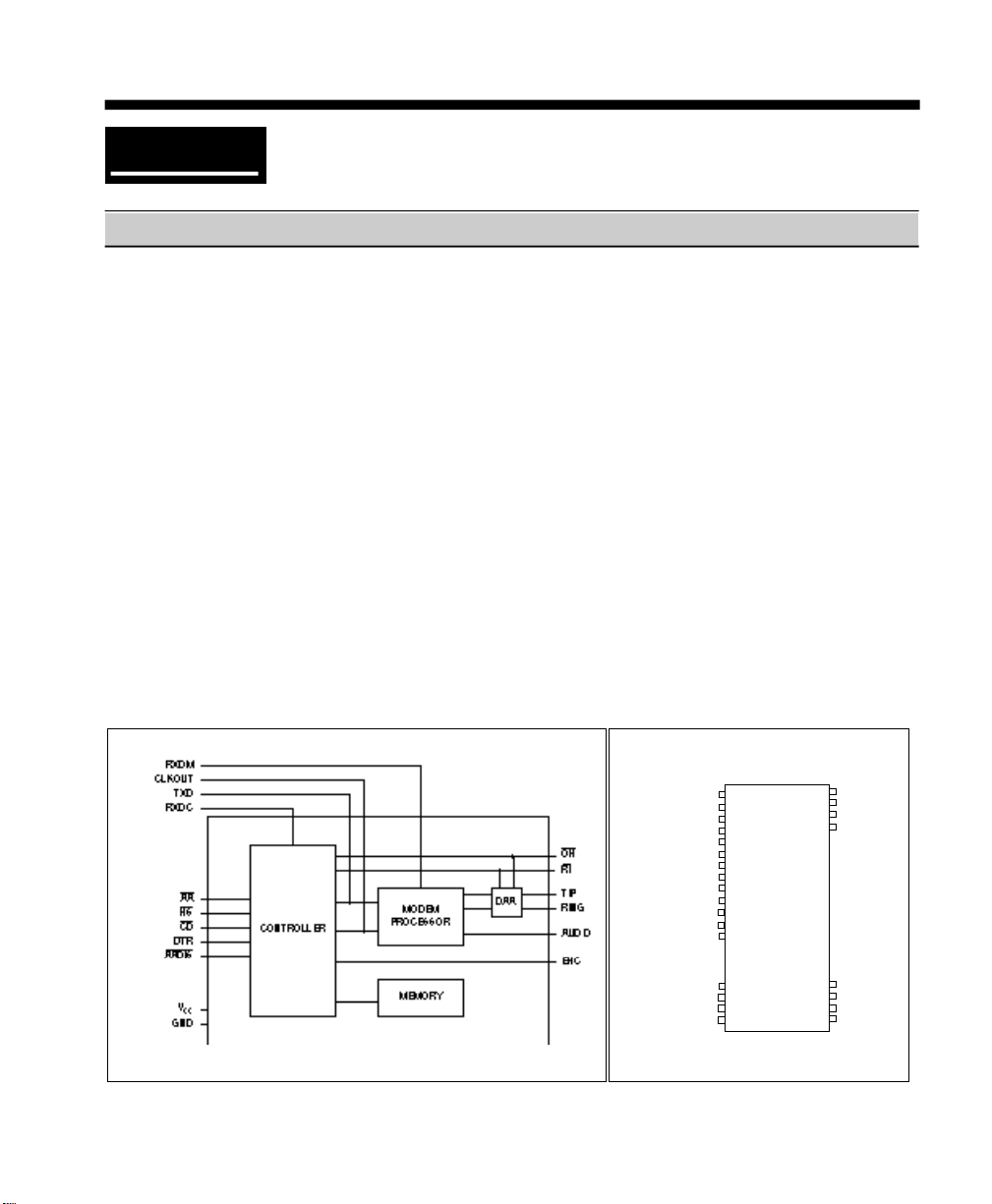
Block Diagram
Features
• Small Size -2.28" x 1.0" x 0.5"
• FCC Part 68 Registered
• Fully Bell 212A/103 and CCITT V.22/V.21
Compatible
• Complete Industry Standard "AT" Command
Set
• TTL Serial Interface
• Call Progress Monitoring
• DTMF and Pulse Dialing
• Software Controlled Audio Output
• UL Recognized Component
• CSA Recognized Component
• +5 Volt Power Only
PIN CONFIGURATION
1 • 40
AA\
HS\
CD\
DTR\
RXDC
N/C
EHC
RXDM
TXD
CLKOUT
AADIS\
OH\
2 39
3 38
4 37
5
6
7
8
9
10
11
RI\
12
13
VCC
GND
N/C
AUDIO
17 24
TIP
18 23
N/C
19 22
N/C
20 21
RING
N/C
N/C
N/C
N/C
Page 2

Pin Descriptions
PIN NAME I/O DESCRIPTION
1 AA O AA goes low when the XE1214B5 is set in the auto-answer mode,
2 \HS O This output, when low, indicates that the modem is in the high speed
3 \CD O \CD indicates detection of a remote modem by going low. If the
4 \DTR I A low on \DTRallows the XE1214B5toll execute data call commands. If
5 RXDC O The XE1214B5 internal controller (see block diagram) uses RXDC to
6 N/C --- No Connection.
either by switch input AA DIS (pin 12) or register S0. If the XE1214B5
is not set to automatically answer (pin 12 held low, or S0 = 0), AAl
follows the incoming ring signal, going low for the 4 sec interval
between rings. For display purposes, this output may be used to drive
an external LED through a 330 ohm resistor.
(1200 bps) mode. When high, it indicates that the modem is in the low
speed (300 bps) mode. For display purposes, this output may be used
to drive an external LED through a 330 ohm resistor.
connection is broken, or never established| \CD remains high. For
display purposes, this output may drive an external LED through a 330
ohm resistor.
this input is driven high during a data call, the XE1214B5 terminate the
data call, hang up the phone line and return to the command state.
transfer serial data in an asynchronous start/stop format at the data rate
selected by the terminal. This data is either the echo of commands
received from the terminal, or result codes generated by the controller
during processing of commands. It is normally high, and should be
"AND"ed with RXDM (pin 8) to form the received data to the terminal.
7 EHC O External Handset Control, when activated by the H1 Command, is used
8 RXDM O The internal modem processor of the XE1214B5B5 (see block diagram)
to control an additional relay to allow an independent handset to be
connected to the telephone line. During data transmission, when the
relay in the internal DAA is closed (off-hook), this output is low. When
the internal relay is open (on-hook), this output is high,and may be used
to control an external relay to connect a telephone handset to the line.
demodulates the received carrier and outputs data on this pin. A logic
low level is "space" and a logic high is "mark". This output is normally
high, and should be "AND"ed with RXDC (pin 5) to form the received
data signal to the terminal.
2/XECOM XE1214B5
Page 3

Pin Descriptions
PIN NAME I/O DESCRIPTION
9 T X D I This is the input for data to be transmitted. The internal controller of
the XE1214B5 receives command data from the terminal on this input
while the internal modem processor receives data from the terminal
on this input for modulation. A logic low is "space" and a logic high is
" m a r k " .
1 0 C L K O U T O The buffered internal clock signal is output on this pin. Its frequency
is 7.3728 MHz and it can drive one LS TTL load.
1 1 \ R I O Ring Indicator. A low level on this status line indicates the ring portion
of the ring cycle. This line is normally used for test/status purposes
o n l y .
1 2 \ A A D I S I When this input is held low, the XE1214B5 will not answer incoming
calls. When held high or left open, the XE1214B5 will automatically
answer incoming calls on the first ring. This function may also be
enabled/disabled by writing to the S0 register.
1 3 \ O H O Off Hook status monitor. This status line allows the user to monitor
the status of the hookswitch relay in the internal DAA (see block
diagram). When the signal on OH is low, the internal relay is closed
and the XE1214B5 is connected to the phone line. During rotary
dialing, this pin is pulsed at a rate of 10 pps with appropriate
Make/Break ratio depending on the 212A or V.22 mode selected.
1 4 - 1 6 N / C - - - No connection.
1 7 , 2 0 T I P - R I N G - - - These pins are for the TIP and RING connections to the telephone
line from the internal DAA. In order to preserve the high voltage
isolation provided by the DAA, traces from these pins to the RJ11C
Jack should have a minimum spacing of 150 mils between them and
any other traces on the PC board.
1 8 , 1 9 N / C - - - No connection.
2 1 - 2 4 N / C - - - No connection.
3 7 A U D I O O The output of the internal hybrid 2-4 wire converter is brought out on
this pin through an internally programmable attenuator. The
attenuation level may be set by the ATL command.
3 8 N / C - - - No connection.
3 9 G N D - - - Ground (0 volts).
4 0 V C C - - - Positive supply voltage (+5 volts).
XE1214B5 3\XECOM
Page 4

S-Register Description
Register Range/Units Default Description
S0 0-255/rings 1 Number of rings before the XE1214B5 answers the call. With
S1 0-255/rings 0 Number of rings detected. S1 is cleared if no ring occurs
S2 0-127/ASCII 43 ASCII value for the escape code. Values greater than 127 are
S3 0-127/ASCII 13 ASCII value for carriage return. The character in S3 is used
S4 0-127/ASCII 10 ASCII value for line feed. The XE1214B5 sends a line feed
S5 0-32, 127/ASCII 8 ASCII value for backspace. This character is both the
S6 2-255/sec. 2 Waiting time before dialing when X0, X1 or X3 is enabled.
S7 1-255/sec. 30 The time the XE1214B5 waits for carrier signal detection from
S8 0-255/sec. 2 Pause time for each comma. The comma is used during
S9 1-255/0.1 sec. 6 The time required for the carrier signal from a remote modem
S10 1-255/0.1 sec. 14 The time between the loss of carrier from a remote modem
S0=0, the XE1214B5 does not answer the call. With S0=5,
the XE1214B5 answers the call on the fifth ring.
within 8 seconds. S1 operates only if S0 is not zero.
not accepted, but do disable escape code operation.
for both the command line and the result code terminators.
after it sends a carriage return only when English word result
codes have been selected (V1). If a line feed is not needed, it
can be set to a null. But this function cannot be disabled.
backspace key and the character echoed to move the cursor
back one position. The values between 33 and 126, the range
of printable ASCII characters are not accepted.
Values greater than 2 seconds may be necessary if trouble
is encountered getting dial tones.
remote modem before hanging up. If the XE1214B5 does not
detect a carrier signal within that time, it hangs up and a NO
CARRIER result code is displayed. If it does, a CONNECT
result code (or (CONNECT 1200 when X1, X2, X3 or X4 is
enabled) is displayed and the XE1214B5 goes on line. Also
used to control time-out of W command.
dialing when it is necessary to dial out of a PBX and wait for a
second dial tone. Two seconds is usually enough, however
the default may be changed or multiple commas may be used
for longer time delays.
must be present for the XE1214B5 to recognize it as a carrier
and signal a carrier detection. This feature prevents the
XE1214B5 from mistaking a carrier signal for a ring or busy
signal. The Units are in tenths of seconds.
and hangup. With S10 equal to 255, XE1214B5 acts as if
carrier is always present. If S10 is smaller than S9,
XE1214B5 disconnects for short loss of carrier. This is
because S10 will time out before the carrier detect response
time expires. The Units are in tenths of seconds.
4/XEC0M XE1214B5
Page 5

Register Range/Units Default Description
S11 50-255/msec. 75 Duration and spacing of touch-tones. Note that pulse dialing
S12 20-255/0.02 sec 50 The time delay required both before and after entering the
S13 bit mapped — XE1214B5 status register (see Note 1)
S14 bit mapped 170 XE1214B5 option register
S15 bit mapped XE1214B5 flag register
S16 0,1,4 This register is used to test analog loopback, digital loopback
is fixed at 10 pulses per second.
escape command (+ + +). The Units are in 20 millisecond
intervals.
bit 0 - undefined (Note 2)
bit 1 - undefined
bit 2 - 0 parity disabled
1 parity enabled
bit 3 - 0 odd parity
1 even parity
bit 4 - 0 seven data bits
1 eight data bits
bit 5 - undefined
bit 6 - 1 buffer overflow flag
(causes ERROR result code to be sent)
bit 7 - 0 8th data bit set to space (if bit 4 + 1)
1 8th data bit set to mark (if bit 4 = 1)
bit 0 - 1 auto answer enabled
bit 1 - 0 local echo disabled
1 local echo enabled
bit 2 - 0 result code enabled
1 result code disabled
bit 3 - 0 result codes sent as digits
1 result codes sent as words
bit 4 - 0 enable command recognition
1 disable command recognition
bit 5 - 0 67/33% make/break ratio
1 61/39% make/break ratio
bit 6 - 0 CCITT V.22/V.21
1 Bell 212A/103
bit 7 - 0 long space disconnect disabled
1 long space disconnect enabled
bit 0 - same as setting of bit 4
bit 1 - same as setting of bit 5
bit 2 - 0 answer mode
1 originate mode
bit 3 - 0 half duplex
1 full duplex
bit 4 bit 5
0 0 undefined
1 0 110 bps
0 1 300 bps
1 1 1200 bps
bit 6 - 0 no connection
1 connection established
bit 7 - undefined
and remote digital loopback.
XE1214B5 5\XECOM
Page 6

Offline Analog Loopback
Before entering offline analog loopback, the telephone line must be disconnected. Normal line
signals may disrupt modem performance during the analog loopback test. The test is started by
entering the following commands: Answer Mode - ATS16 = 1A
Originate Mode - ATS16 - 1O
With both commands, a CONNECT result code is displayed and subsequent characters typed on
the keyboard are displayed on the screen. The test may be ended by the escape command. S16
may be reset to zero by the H command.
Online Analog Loopback
This test is useful in the event that the XE1214B5 is on line with a remote modem and is receiving
many errors. The test is started by entering the command: ATS16 = 1O
The O command puts the XE1214B5 back on line. All characters entered on the keyboard should
be transmitted to the remote modem and displayed on the screen. If the information is correctly
displayed, then XE1214B5 is working properly and the problem is either in the phone line or with
the remote modem. To finish the test and return on line in the normal mode enter the command:
ATS16 = 0O
Digital Loopback
This test causes the modem to resend each received character. It is used for testing a remote
modem. The modems must be connected before the test. The test is started with the commands:
ATS16 = 4O
All the characters entered by the remote modem are looped back to its screen through the
XE1214B5 and are not displayed on the local screen.
Remote Digital Loopback
This test enables the remote modem to loop received data back to the transmitting modem. It is
useful when meaningless data is received from the remote modem or vice versa. To execute the
test, the remote modem must be capable of operating in remote digital loopback. The test is
started by the command: ATO2
To exit this test and go back on line enter the command: ATO1
Audio Output Stage
A programmable attenuator that can drive a load impedance of 50K is provided to allow monitoring
of the telephone line signal through an external speaker. Four levels of signal (high, medium, low
and off) are provided through the L and M commands as well as the capability to automatically turn
the signal off when a data connection is established. The output of the attenuator is available on
the Audio Output (pin 12) and may be used with an external audio amplifier (such as an LM386) to
drive a low impedance speaker. The output can directly drive a high impedance transducer,
however the output may be low.
6/XECOM XE1214B5
Page 7

AT Data Commands
AT Command line prefix; Must preceed all of the commands, except for the A/ command.
A Answer incoming call immediately.
A/ Re-execute last command line, don't precede this command with AT or press <Enter> at the end of the
command line
B Uses Bell or CCITT z answer tone at 1200 bps
C Modem carrier signal on
Dn Dial telephone number n; you can also include the following Dial string modifiers:
E Command echo
F Full or half Duplex
H switch hook control
I Product code
L Speaker volume
M Speakercontrol
O Return to on-line mode
Q Result codes (default)
Sr? Read and display value of register r
Sr=n Set register r value to n
V Full Word or numeric result codes
X4 Response set,
Y Long space disconnect disabled
Z Resets modem and sets modem to factory default states
P Pulse dialing
R Originate call in answer mode
T Touch-Tone dial
; Return to Command Mode after dialing
, Pause (default 2 seconds; see register S8)
! 0.5-second hookflash
/ Wait for 1/8 second
@ Wait for silence (default 5 seconds)
W Wait for dial tone (default 30 secs; see register S7)
Result Code Summary
Digit Code Word Code Meaning
0 OK Successfully executed command line
1 CONNECT 300 bps connection established
2 RING Ring signal detected
3 NO CARRIER Carrier not detected within Register S7 detect time
4 ERROR Error found in command line; returns to command line
5 CONNECT 1200 1200 bps connection established
6 NO DIAL TONE No dial tone detected within 5 Sec. after going off-hook
7 BUSY Busy signal detected after automatically dialing a call
8 NO ANSWER Five seconds of silence was not detected when using the
@ command in the Dial command line
Note: When the XE1214B5 detects ringing on the telephone line, it sends a Ring result code.
However, the XE1214B5 will answer call only if it is in auto-answer mode (ATSO>0) or is
given an ATA.
XE1214B5 7\XECOM
Page 8

Typical Connection Diagram
Mechanical Specifications
INCHES METRIC(MM)
DIM MIN MAX MIN MAX
A 2.255 2.305 57.2 58.6
B 0.985 1.015 25.0 25.8
C 0.490 0.510 12.4 13.0
D 0.890 0.910 22.6 23.1
E 1.890 1.910 48.0 48.5
F 0.125 0.200 3.1 5.1
G 0.040 0.060 1.0 1.5
H 0.180 0.200 4.5 5.1
J 0.090 0.110 2.3 2.8
XECOM/8 XE1214B5
Page 9

Electrical Specifications
ABSOLUTE MAXIMUM RATINGS*
SUPPLY VOLTAGE - Vcc +6 Volts
DC INPUT VOLTAGE -0.6 Volts to (Vcc +0.6 Volts)
STORAGE TEMPERATURE RANGE -25° C TO +85° C
LEAD TEMPERATURE(Soldering, 2 seconds per wave) 260° C
OPERATING TEMPERATURE RANGE 0 TO 70° C
*Exceeding these values may result in permanent damage to the device.
D.C. Electrical Specifications
(TA = 0 - 70°C, Vcc = 5v ±10%)
Description Parameter Min Typ Max Units
Power Supply Voltage Vcc 4.5 5.0 5.5 Volts
Power Supply Current Icc (on-hook) 28.0 50.0 mA
Icc (off-hook) 68.0 100.0 mA
High Level Input Voltage Vih 2.0 Volts
Low Level Input Voltage Vil 0.8 Volts
High Level Output Voltage Voh 3.5 Volts
Low Level Output Voltage Vol 0.4 Volts
Leakage Current ± 1.0 uA
Telephone Line Interface Specification
Description Min Typ Max Units
Telephone Line Impedance Match 600 Ohms
Ring Detect Sensitivity (on hook, Type B Ringer) 38 Vrms
DC Telephone Line Current 0 20 100 milliamps
XE1214B5 9\XECOM
Page 10

Transmitter Specifications
Description Parameter Min Typ Max Units
Input Character Start Bit=Data Bit 10 bits
Length + Stop Bit
Character Bit Rate 1170 1200 1212 bps
Carrier Output Level -10 -9 dBm
DTMF Row Output Level -6 dBm
DTMF Column Output Level -4 dBm
1800 Hz Guard Tone -16 dBm
Receiver Specifications
Description Min Typ Max Units
Received Signal Range -45 0 dBm
Character Bit Rate 1170 1200 1224 dps
Carrier Detect Level -48 -43 dBm
Carrier Detect Hysteresis 2
Carrier Detect Delay 10 20 30 msec
Carrier Detect Hold 15 20 24 msec
XECOM/10 XE1214B5
Page 11

FCC Instructions
This product complies with part 68 of the FCC Rules and Regulations. With each device shipped,
there is a label which contains, among other information, the FCC Registration Number and Ringer
Equivalence Number (REN) for this product. You must, upon request, provide this information to
your telephone company.
The mounting of this device in the final assembly must be made in such a manner as to preserve
the high voltage protection between the TIP/RING Connection and the rest of the system.
Typically, this may be accomplished by maintaining a minimum spacing .100 mils between the
TIP/RING Traces to the RJ-11C Jack and low voltage portion of the system. No additional circuitry
may be attached between TIP/RING and the telephone line connection, unless specifically allowed
in the rules.
The REN is useful to determine the quantity of devices you may connect to a telephone line and
still have all of these devices ring when the number is called. In most, but not all areas, the sum of
the RENs of all devices connected to one line should not exceed five (5.0). To be certain of the
number of devices you may connect to the line, as determined by the REN, you should contact the
local telephone company to determine the maximum REN for you calling area.
If your system causes harm to the telephone network, the telephone company may discontinue
service temporarily. If possible, they will notify you in advance. If advance notification is not
practical, you will be notified as soon as possible.
Your telephone company may make changes in its facilities, equipment, operations or procedures
that could affect proper functioning of your equipment. If they do, you will be notified in advance to
give you an opportunity to maintain uninterrupted telephone service.
If you experience trouble with this device, please contact XECOM at (408) 945-6640 for
information on obtaining service or repairs. The telephone company may ask you to disconnect
this device from the network until the problem has been corrected or until you are sure that the
device is not malfunctioning.
The device may not be used on coin service lines provided by the telephone company (this does
not apply to private coin telephone applications which use standard telephone lines). Connection
to party lines is subject to state tariffs.
FCC Registration Number DWEUSA-65595-MD-E
Ringer Equivalence 0.9B
XE1214B5 11\XECOM
Page 12

Terms of Sale
Devices sold by XECOM are covered by the warranty provisions appearing in its Terms of Sale
only. XECOM makes no warranty, express, statutory, implied, or by description regarding the
information set forth herein, or regarding the freedom of the described devices from patent
infringement. XECOM makes no warranty of merchantability or fitness for any purposes. XECOM
reserves the right to discontinue production and change specifications and prices at any time and
without notice. This product is intended for use in normal commercial applications. Applications
requiring extended temperature range, unusual environmental requirements, or high reliability
applications, such as military, medical life-support or life-sustaining equipment, are specifically not
recommended without additional processing and authorization by XECOM for such application
Xecom assumes no responsibility for the use of any circuitry other than circuitry embodied in a
Xecom product. No other circuits, patents, or licenses are implied.
Life Support Policy
Xecom's products are not authorized for use as Critical Components in Life Support Devices or
Systems.
Life Support Devices or Systems are devices or systems which, (a) are intended for surgical
implant into the body, or (b) support or sustain life, and whose failure to perform, when properly
used in accordance with instructions provided in the labeling, can be reasonably expected to result
in significant injury to the user.
A Critical Component is any component of a life support device or system whose failure to
perform can be reasonably expected to cause failure of the life support device or system, or to
affect its safety or effectiveness.
Copyright, Xecom © 1993
While Xecom, Inc. has made every effort to ensure that the information presented here is accurate, Xecom will
not be liable for any damages arising from errors or omission of fact. Xecom reserves the right to modify
specifications and/or prices without notice. Product mentioned herein are used for identification purposes only
and may be trademarks and/or registered trademarks of their respective companies.
X e com Incorporated
XECOM
374 Turquoise Str eet ,Mi lpitas, CA 95035
Ph:408-945 -66 40 Fax:4 08-94 2 - 1 346
 Loading...