

Page 1
XECOM XE1212C
1200bps Modem Module with Parallel Host Interface
XE1212C
6/97
xecom
Features
•
Small Size -2.28" x 1.0" x 0.5"
• FCC Part 68 Registered
• 212A/103 and CCITTV.22/V.21 Compatible
• Industry Standard "AT" Command Set
• Parallel Interface Emulates 8250B UART
• Call Progress Monitoring
• DTMF and Pulse Dialing
• Software Controlled Audio Output
• Modem Configuration storage in NVRAM
• +5 Volt Power Only
Typical Operating Power 200 mW
Automatic Sleep mode when idle reduces power
consumption to only 50 mW.
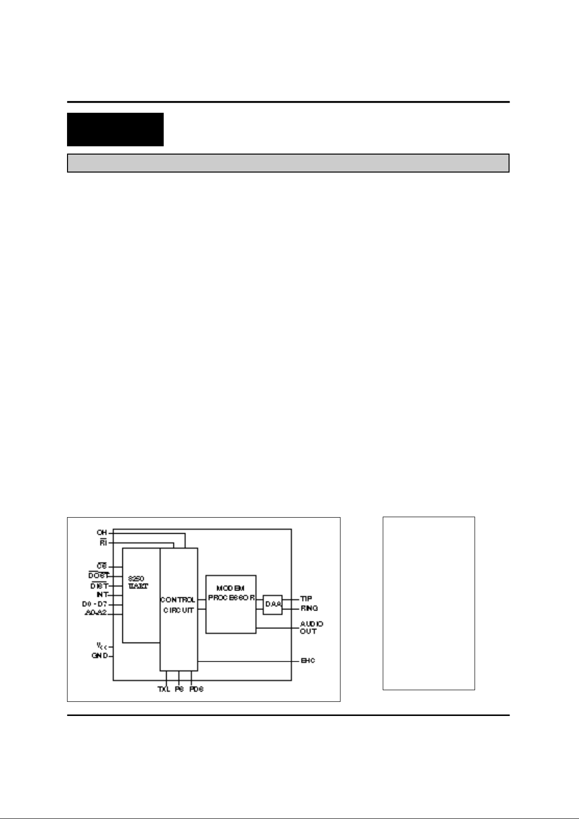
Description
The XE1212C is a complete 1200/300 bps
Modem in a compact, component form factor. It
contains all circuitry necessary for complete
modem functionality, including an FCC Part 68
Registered Data Access Arrangement (DAA) for
direct connection to the telephone line, and a
parallel 8250B UART interface for direct operation
with the IBM-PC, XT or AT system bus. It
operates from the industry standard 'AT'
command set. The XE1212C contains all signal
processing functions, including the modulators
and demodulators for both PSK and FSK
operation, and analog filters.
The XE1212C includes the capability for call
progress monitoring and DTMF tone generation
as well as the guard tones handling required for
CCITT V.22/V.21 communications. It operates in
the asynchronous mode and provides analog
loopback, digital loopback and remote digital
loopback functions for testing.
Block Diagram
1 • 40
2
3
4 37
5
6
7
8
9
10
11
12
13 28
14 27
15 26
16 25
17 24
18 23
19 22
20 21
N/C
GND
Vcc
RI\
N/C
N/C
N/C
N/C
OH
N/C
N/C
AUDIO
INT
A0
A1
A2
CS\
DOST\
DIST\
EHC
TIP
RING
D0
D1
D2
D3
D4
D5
D6
D7
PIN CONFIGURATION
Page 2
XECOM (2) XE1212C
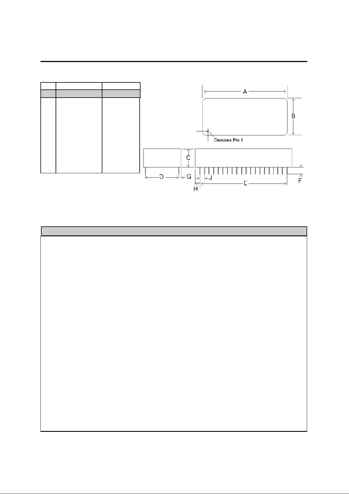
Mechanical Specifications
Pins = 0.020" X 0.014"
All pins tin-plated
Recommended hole size = 0.045"
A 2.255 2.305 57.2 58.6
B 0.985 1.015 25.0 25.8
C 0.490 0.510 12.4 13.0
D 0.890 0.910 22.6 23.1
E 1.890 1.910 48.0 48.5
F 0.125 0.200 3.1 5.1
G 0.040 0.060 1.0 1.5
H 0.180 0.200 4.5 5.1
J 0.090 0.110 2.3 2.8
Inches Milimeters
Min Max Min Max
PIN NAME DESCRIPTION
Pin Descriptions
1 N/C No Connect.
2 GND Ground Reference (0 volts).
3 VCC Positive Supply Voltage (+5 volts).
4 \RI Ring Indication. A low level on this status line indicates the presence of the ring cycle on
Tip and Ring. This line is normally used for test/status only.
5,6,7,8 N/C No Connect
9 OH This signal allows the user to monitor the status of the hookswitch relay in the XE1212C.
When the signal on OH is high, the relay is closed, and the XE1212Csiezes the telephone
line. During rotary dialing, this line is pulsed at a rate of 10 pulses per second.
10,11 N/C No Connect
12 AUDIO A programmable attenuator that can drive a load impedance of 300 ohms is provided on
this pin to allow monitoring of the telephone line signal through an external speaker. The L
and M commands adjust speaker volume and control when the audio signal will be
presented. The Audio Output in conjunction with an external audio amplifier (such as an
LM386) can drive a low impedance speaker.
13 INT The Interrupt Line goes high whenever any of the enabled interrupts in the Interrupt Enable
Register (IER) is active. The interrupts are Received Data Available, Transmitter Holding
Register Empty, Receiver Line Status and Modem Status. The Interrupt Line is reset upon
the appropriate interrupt servicing. This pin is forced to a Hi-Z state when bit 3 bit of the
modem control register (MCR) is low (power on state).
14-16 A0..A2 These 3 address inputs select a UART register during read or write operations as shown in
Table 1. The Divisor Latch Access Bit (DLAB) of the LCR register must be set high by the
system software to access the bit rate Divisor Latch (DLM) as shown in Table 2.
Page 3

XECOM (3) XE1212C
17 \CS The XE1212C is selected when Chip Select is driven low. When high, the data bus lines
(D0..D7) will be in the high impedance state.
18 \DOST The CPU can write data or control words into a selected register of the XE1212C when
DOST and CS are low. Data is latched on the rising edge of the signal.
19 \DIST The CPU can read data or status from a selected register of the when DIST and CS are
low.
20 EHC External Handset Control. This pin is used to control an additional relay to connnect a
telephone handset to the telephone line. During data transmission, when the internal relay
in the DAA is closed (off hook), this pin is high. When the internal relay is open (on-hook),
this pin is low and may be used to close an external relay to connect the telephone handset
to the line.
21-28 D7-D0 This eight bit data bus provides bidirectional communications between the modem and
CPU. Data, Control words and Status information are transferred on these bus lines.
These are tri-state lines and have internal drive buffers eliminating the need for external
buffering between the CPU bus and the XE1212C.
37,40 RING/TIP These are the TIP and RING connections to the telephone line from the DAA. In order to
maintain the high voltage isolation provided by the DAA, traces from these pins to the
RJ11C Jack should have a minimum spacing of 100 mils between them and any other
traces on the board.
PIN NAME DESCRIPTION
Pin Descriptions
ABSOLUTE MAXIMUM RATINGS*
SUPPLY VOLTAGE - Vcc +6 Volts
DC INPUT VOLTAGE -0.6 Volts to (Vcc +0.6 Volts)
STORAGE TEMPERATURE RANGE -25° C TO +85° C
LEAD TEMPERATURE 260° C
(Soldering, 2 seconds per wave)
OPERATING TEMPERATURE RANGE 0 TO 70° C
*Exceeding these values may result in permanent damage to the device.
Page 4
XECOM (4) XE1212C
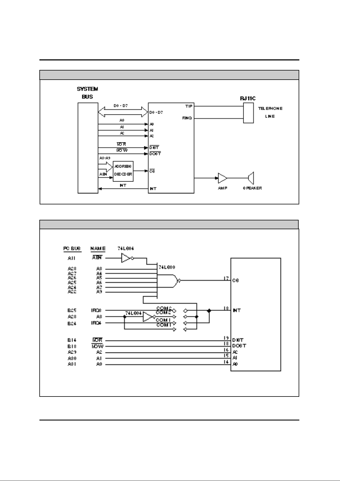
IBM-PC Bus Interface Address Decoder
XE1212C
Typical Connection Diagram
XE1212C
Page 5

XECOM (5) XE1212C
0 0 1 2 3 4 5 6 0 1
(DLAB=0) (DLAB=0) (DLAB=0) (DLAB=1) (DLAB=1)
Transmit
Set Shift Ring
6 Data Bit Data Bit 0 0 Break 0 Register Indicator Bit 6 Bit 14
6 6 1=SB Empty (RI)
(TSRE)
Receiver Transmitter Interrupt Interrupt Line Modem Line Modem Divisor Divisor
Bit Buffer Holding Enable Indent. Control Control Status Status Latch Latch
No. Register Register Register Register Register Register Register Register (DLL) (DLM)
(RBR) (THR) (IER) (IIR) (LCR) (MCR) (LSR) (MSR)
Enable "0" if Word Length Data
0 Data Bit Data Bit RXD Interrupt Selection Terminal Data Delta Bit 0 Bit 8
0* 0* Available Pending Bit 0 Ready Ready CTS
Interrupt (DTR)
Enable
Transmitter Interrupt Word Length Request Overrun Delta
1 Data Bit Data Bit Holding Ident. Selection to Send Error DSR Bit 1 Bit 9
1 1 Reg. Empty Bit 0 Bit 1 (RTS) (OE)
Interrupt
Enable Trailing
Receiver Interrupt Stop Bits Output 1 Parity Edge
2 Data Bit Data Bit Line Status Ident. 0=1 SB Error Ring Bit 2 Bit 10
2 2 Interrupt Bit 1 1=2 SB (PE) Indicator
Enable Parity Framing Delta
3 Data Bit Data Bit Modem 0 Enable Output 2 Error Rx Line Bit 3 Bit 11
3 3 Status 1=PEN (FE) Signal
Interrupt Detect
4 Data Bit Data Bit 0 0 Even Parity Local Break Clear to Bit 4 Bit 12
4 4 Select Loopback Interrupt Send
1=EPS (CTS)
Stick Transmit
5 Data Bit Data Bit 0 0 Parity 0 Holding Data Set Bit 5 Bit 13
5 5 1=SP Register Ready
Empty (DSR)
(THRE)
Divisor Received
Latch Line
7 Data Bit Data Bit 0 0 Access 0 0 Signal Bit 7 Bit 15
7 7 Bit Detect
(DLAB)
UART Register Function Summary
Register Address
*Bit 0 is the least significant bit. It is the first bit serially transmitted or received.
Page 6

XECOM (6) XE1212C
0 0 0 0 Receiver Buffer (read only) (RBR)
0 0 0 0 Transmitter Holding (write only) (THR)
0 0 0 1 Interrupt Enable (IER)
X 0 1 0 Interrupt Identification (read only) (IIR)
X 0 1 1 Line Control (LCR)
X 1 0 0 Modem Control (MCR)
X 1 0 1 Line Status (LSR)
X 1 1 0 Modem Status (read only) (MSR)
X 1 1 1 Scratch Register (Not Used by the Modem)
1 0 0 0 Divisor Latch (DLL)
1 0 0 1 Divisor Latch (DLM)
DLAB A2 A1 A0 REGISTER
UART Register Addresses
Interrupt Identification Register
The XE1212C Interrupt capability emulates the industry standard 8250 UART. This minimizes software overhead
during data character transfers, the XE1212C prioritizes interrupts into four levels. The Interrupt Identification
Register indicates that an interrupt is pending and identifies the source of the interrupt. When this register is
addressed during chip select time, it freezes the highest priority interrupt pending and no other interrupts are
acknowledged until the CPU services that interrupt. The table below defines the interrupt priorities and the contents
of the Interupt Identification Register.
IIR Register Bit Description
0 This bit indicates if an interrupt is pending. When bit 0 is a logic 0, an interrupt is pending
and the IIR contents may be used as a pointer to the appropriate interrupt service
routine. When bit 0 is logic 1, no interrupt is pending.
Bit 1 Bit 2 Interupt Priority Interrupt Definition
1 1 (priority 1) Receiver Line Status
0 1 (priority 2) Received Data Ready
1 0 (priority 3) Transmitter Holding Register Empty
0 o (priority 4) MODEM Status
3-7 These five bits of the Interrupt Identification Register are always a logic 0.
Page 7

XECOM (7) XE1212C
Interrupt Enable Register
This 8-bit register enables the four interrupt sources of the XE1212C to separately activate the Interrupt line (INT,
pin 13). It is possible to totally disable the Interrupt system by resetting bits 0 through 3 of the Interrupt Enable
Register. similarly, by setting the appropriate bits of this register to a logic 1, selected interrupts can be enabled.
Disabling the interrupt system inhibits the Interrupt Identification Register and the active (high) INT output from the
XE1212C. All other system functions operate in their normal manner, including the setting of the Line Status and
Modem Status Register. The contents of the Interrupt Enable Register are described below.
IER Bit Description
Bit 0: This bit enables the Received Data Available Interrupt when set to logic 1.
Bit 1: This bit enables the Transmitter Holding Register Empty Interrupt when set to a logic 1.
Bit 2: This bit enables the Receiver Line Status Interrupt when set to logic 1.
Bit 3: This bit enables the MODEM Status Interrupt when set to logic 1.
Bit 4-7: These four bits are always logic 1.
Bit 0-1: Bits 0 and 1 specify the number of bits in each transmitted or received character. the encoding of
the bits is as follows:
Bit 1 Bit 0 WORD LENGTH
0 0 5 Bits
0 1 6 Bits
1 0 7 Bits
1 1 8 Bits
Bit 2: This bit specifies the number of stop bits in each transmitted or received character. If bit 2 is a
logic 0, one stop bit is generated or checked in the transmit or receive data, respectively. If bit 2 is
a logic 1 when 7-bit word length with no Parity is selected, two stop bits are generated or checked.
Bit 3: This bit is the Parity Enable bit. When bit 0 is a logic 0 and bit 3 is a logic 1, a Parity bit is
generated (transmit data) or checked (receive data) between the last data word bit and the Stop
bit of the serial data. (The Parity bit is used to verify that the data has been transmitted intact.)
Bit 4: This bit is the Even Parity Select bit. When bit 3 is a logic 1 and bit 4 is a logic 0, an odd parity
is transmitted or checked for in the received data. When bit 3 is a logic 1 and bit 4 is a logic 1,
even parity is transmitted or checked.
Bit 5: This bit is the Stick Parity bit. when bit 3 is a logic 1 and bit 5 is a logic 1, a 1 is placed in the
parity bit.
Bit 6: This bit is the Set Break Control bit. When bit 6 is a logic 1, the modem output is forced to the
Space state (logic 0) and remains there until reset regardless of other transmitter activity. This
feature enables the CPU to alert a terminal in a computer communications system.
Bit 7: This bit is the Divisor Latch Access bit (DLAB). It must be set high (logic 1) to access the Divisor
Latches of the Baud Rate Generator during a Read or Write operation. It must be set low (logic 0)
to access the Receiver Buffer, the Transmitter Holding Register, or the Interrupt Enable Register.
Line Control Register
Page 8

XECOM (8) XE1212C
Programmable Baud Rate Generator
The XE1212C Baud Rate Generator can be programmed for one of four Baud rates. The desired speed is selected
by writing into the Divisor Latch (DLM) MSB and LSB registers.
(HEX CODE) Decimal
DLM DLS DIVISOR BAUD RATE
00 30 48 2400
00 60 96 1200
00 C0 192 600
01 80 384 300
This 8-bit register controls the interface with the Modem Processor as shown in the block diagram. The contents of
the Modem Control Register are described below.
Bit 0: This bit controls Data Terminal Ready (DTR) signal.
Bit 1: This bit controls the Request to Send (RTS) signal.
Bit 2: Output 1; Tied to RI during Local Loopback
Bit 3: Output 2; When this bit is a 0, INT (pin 13) is in the high-Z state.
Bit 4: Selects Local Loopback Operation: Data presented to the Transmit holding Register is lopped
back to the Receiver Buffer Register. The modem control bits CTS, DSR, RI and DCD are
internally connected to the modem control outputs; RTS, DTR, Output 1, and Output 2.
Bit 5-7: These bits are permanently set to logic 0.
Modem Control Register
Modem Status Register
This register shows the current state of the control lines from the ModemProcessor to the CPU. It also indicates if
changes have occurred in these control lines. Bits 0-3 are set to a logic 1 whenever a control input from the
ModemProcessor changes state. These bits are reset to logic 0 whenever the CPU reads the Modem Status
Register. The contents of the Modem Status Register are described below.
Bits 0: This bit indicates that CTS has changed since the Modem Status Register was last read.
Bits 1: This bit indicates that DSR has changed since the Modem Status Register was last read.
Bit 2: This bit is the Trailing Edge of Ring Indicator detector. Bit 2 indicates that RI (pin 4) has changed
from an On (logic 1) to an Off (logic 0) condition.
Bit 3: This bit is the Delta Received Line Signal Detector Indicator. Bit 3 indicates that the carrier
detector has changed state.
Bit 4: This bit displays the status of Clear to Send.
Bit 5: This bit displays the status of Data Set Ready
Bit 6: This bit displays the complement of RI (pin 4).
Bit 7: This bit displays the status of DCD, Received Line Signal Detect.
Note 1: Whenever bit 2 or 3 is set to logic 1, a Modem Status Interrupt is generated.
Page 9

XECOM (9) XE1212C
AT Commands
The XE1212C uses "AT" commands for modem configuration. This section describes the command format
and lists the commands, registers and result codes.
Modes of Operation
The "AT" commands have two operational modes;
Command Mode and Data Mode.
Data Mode: The XE1212C enters data mode upon
connecting with a remote modem and issues an
appropriate "CONNECT" result code. In Data Mode the
modem sends all data presented on Transmit Data
(TXD) to the remote modem and places demodulated
data from the remote modem onto Received Data
(RXD). When the modem exits data mode, it issues the
"NO CARRIER" result code.
Command Mode: The XE1212C enters command
mode on power-up, reset, a lost connection, or receipt
of the escape code. In command mode the modem
accepts commands from the host on transmit data.
Appropriate result codes are returned on received data.
Command Line Format
Command lines issued to the modem follow a strict
format. Each command begins with the prefix AT. The
command line is stored in the command buffer and
executed upon receipt of a carriage return. Until
executed, the command line can be edited with the
backspace key.
Command Prefix - Commands, except A/, begin with
the AT prefix. The "A" and "T" may be both upper case
or both lower case but cannot be of different cases. The
prefix identifies the speed and parity of the host. Speed
is determined by measuring the width of the incoming
bits. Parity is determined by comparing the parity bits of
the "A" and "T." The XE1212C must be intialized at the
desired connect speed on powered-up.
Command Line - Commands may be strung together
in a single command line of up to 40 characters.
Commands are executed in the sequence they appear.
A carriage return terminates the command line and
causes the commands to be executed. Register S3
allows the user to select a character other than a
carriage return to terminate the command line.
Command Buffer - The command buffer stores up to
40 characters, including the AT prefix, from one
command line. Spaces may be inserted into the
command line without filling space in the command
buffer. If the command buffer overflows, the modem
issues an "ERROR" result code and commands are not
executed.
Command Line Editing - A backspace can be used to
edit a command line before execution. The backspace
key, (Control and H simultaneously on some systems),
erases the previous character in the command line.
Register S5 allows the user to select a character other
than a backspace as the command line editor.
Re-Execute Last Command - The A/ command
causes the modem to reexecute the last command line.
This command does not require the "AT" prefix.
Omitted Parameters - Most commands include a
parameter which determine the function setting. When
the command parameter is omitted from the command
string, it is assumed to be a 0.
Escape Characters - An escape sequence may be
entered while in data mode to switch the modem into
command mode while on line. The escape character,
set by Register S2, must be entered 3 times in
succession within a 1 second guard time to execute the
escape. The default escape sequence is "+++."
Result Codes - The modem issues a result code after
each action. Result codes may be provided as full
words, numeric codes or may be disabled all together.
Each result code ends with a carriage return when
numeric result codes are chosen. When full word result
codes are chosen, a Line feed and Carriage Return
preceed and follow each result code.
Page 10

XECOM (10) XE1212C
XE1212C AT Command List
A - Answer Command Bn - Select Communications Standard
n=0 Selects CCITT standards
n=1 Selects Bell standards*
D - Dial Command -
P = Pulse dial
T = Tone dial
R = Connect as an answering modem
W = Wait for dial tone
, = Pause for the duration of S8
@ = Wait for silence
! = Switch hook flash
; = Return to the command state
Sn = Dial number stored in location n
En - Command Echo
n=0 Do not echo commands
n=1 Enable command echo*
Hn - Switch Hook Control -
n=0 Switch hook relay closes*
n=1 The switch hook relay opens
In - Modem Identification
Ln - Speaker Volume -
n=0 Low speaker volume
n=1 Low speaker volume
n=2 Moderate speaker volume*
n=3 High speaker volume
Mn - Speaker Activity -
n=0 Speaker off
n=1 Speaker on until carrier received*
n=2 Speaker remains on
n=3 Speaker on after dialing until carrier detected.
On - On Line
n=0 Return On Line with no retrain*
n=1 No response to remote test request.
Qn - Responses
n=0 Send responses *
n=1 No Responses
Sr? - Interrogate Register Sr=n - Set Register Value Vn - Result Codes -
n=0 Numeric Result Codes
n=1 English Word Result Codes*
Xn - Result Code Set -
n=0 Responses 0-4*
n=1 Responses 0-5
n=2 Responses 0-6
n=3 Responses 0-5, & 7
n=4 Responses 0-8
Z - Reset &Cn - DCD Operation
n=0 DCD is forced active
n=1 DCD indicates a valid carrier signal*
&Dn - DTR
n=0 DTR is ignored by the modem
n=2 Modem disconnects if DTR revoked.*
n=3 The modem performs a soft reset when DTR
is revoked.
&Pn - Pulse Dialing Make-to Break Ratio
n=0 39/61; 10 pulses per second (US, Canada)*
n=1 33/67; 10 pulses per second
n=2 39/61; 20 pulses per second
n=3 33/67; 20 pulses per second
&Sn - DSR Operation
n=0 DSR is forced active*
n=1 DSR on from start of modem handshake
&Tn - Test Modes
n=0 Exit test mode
n=1 Local analog loopback
n=3 Initiate local digital loopback
n=4 Respond to remote loop request*
n=5 Deny remote loop request
n=6 Initiate a Remote Digital loopback
n=7 Remote digital loopback w self-test
n=8 Local analog loopback w self-test
&V - View Active Profile &Wn - Store Profile -
n=0 Stores the current configuration in memory
location 0.
n=1 Stores the current configuration in memory
location 1.
&Yn - Recall Profile
n=0 Use memory location 0.
n=1 Use memory location 1.
&Zn=X- Store Number
* Indicates the default setting for the command as
shipped by Xecom.
Page 11

XECOM (11) XE1212C
S0 0-255/rings Number of rings to answer on 1
S1 0-255/rings Count number of incoming rings 0
S2 0-127/ASCII Escape character 43
S3 0-127/ASCII Carriage return character 13
S4 0-127/ASCII Line feed character 10
S5 0-32,127/ASCII Backspace character 8
S6 2-255/sec Dial tone wait time 2
S7 1-60/sec Wait time for remote carrier in seconds 30
S8 0-255/sec Comma pause time in seconds 2
S9 1-255/0.1 sec Carrier detect response time in tenths of seconds 6
S10 1-255/0.1 sec Delay from loss of carrier to hang up 014
S11 50-255/msec DTMF Dialing Speed in miliseconds 95
S12 0-255/.020 sec Escape code guard timer in 20 millisecond intervals 50
S14 Bit Mapped E,Q,V commands, Tone/Pulse,Originate/Answer 170
S16 Bit Mapped Modem loopback tests 000
S18 0-255/sec Modem test timer in seconds 000
S21 Bit Mapped &D, &C commands 042
S22 Bit Mapped L, M, X, &P commands 118
S23 Bit Mapped &T4,&T5 commands, DTE speed and parity 023
S24 5-254/seconds Slee Mode inactivity timer in seconds 000
S27 Bit Mapped &X, B commands 064
REG. RANGE/UNITS DESCRIPTION DEFAULT
XE1212C S-Register Summary
Symbol Parameter Min Typ Max Units Comments
Vcc Supply Voltage 4.75 5.0 5.25 V
Icc Vcc Supply Current 40 50 mA On-Line All outputs
Disconnected
Icc Vcc Supply Current 7 10 mA Sleep Mode
Power Supply Characteristics(TA = 0 - 70°C, Vcc = 5v ±5%)
Sleep Mode: The XE1212C has an integrated, advanced power management capability. If no activity is detected
on the RXD, DTR, or RI lines the modem will automatically go into a smart power down mode. In this mode power
consumption is less than 50 milliwatts.
Page 12

XECOM (12) XE1212C
Analog Loopback
Before entering analog loopback, the telephone line
must be disconnected. Normal telephone line signals
may affect the results of the analog loopback test. The
test is started by entering the following command,
AT&T1<CR>. A CONNECT result code will be
displayed. All subsequent characters typed on the
keyboard are displayed on the screen. The test may be
ended by the escape command. Register S18
determines the length of the test.
Analog Loopback may also be run using the modem's
internal test pattern. The command A T & T 8 < C R >
initiates the analog loopback with self-test. The test
pattern is looped from the transmitter to the recevier and
checked for errors. The number of errors is reported
when the test terminates.
Digital Loopback
This test causes the modem to automatically resend
each received character. It is used for testing a remote
modem. The modems must be connected before the
test. The test is started with the commands:
AT&T3<CR>. All the characters received from the
remote modem are looped back to it through the
XE1212C and are not displayed on the local screen.
Remote Digital Loopback
This test enables the remote modem to loop received
data back to the transmitting modem. To execute the
test, the remote modem must be capable of operating in
remote digital loopback. The test is started by the
command: A T & T 6 < C R > . During this test, data
transmitted by the XE1212C will be looped back by the
remote modem. The Remote Digital Loopback will
utilize the XE1212C internal test pattern if the test is
intiated with the command AT&T7<CR>.
Modem Diagnostics
Interrupt
Identification Interrupt Set and Reset Functions
Register
B1 B1 B0 Priority Level Interrupt Flag Interrupt Source Interrupt Reset
0 0 1 None None
1 1 0 Highest Receiver Line Overrun Error or Reading LSR
Status Parity Error or
Framing Error
1 0 0 Second Receiver Data Receiver Data Reading the
Available Available RBR
0 1 0 Third Transmitter Transmitter Reading the IRR
Holding Register Holding Register (if source of interrupt)
Empty Empty or Writing toTHR
0 0 0 Fourth Modem Status Ring Indicator or Reading the Modem
or RLSD Status Register
Interrupt Control Functions
Page 13

XECOM (13) XE1212C
Register Reset States
Receiver Buffer Register First Word Received Data
Transmitter Holding Register Write to Transmit Holding Register Data
Interrupt Enable Register Power On Reset All Bits Low (0-3 forced and 4-7 permanent)
Interrupt Identification Register Power On Reset Bit 0 is High and Bits 1-7 are Low
Line Control Register Writing into the LCR Data
Modem Control Register Power On Reset All Bits Low
Line Status Register Power On Reset All bits Low, Except Bits 5 and 6 are high
Modem Status Register Power On Reset Bits 0-2 Low, Bits 3-5 High, Bits 6-7 Low
Divisor Latch (DLM) Power On Reset 2400 bps
INT Power On Reset Low (Hi-Z)
REGISTER/SIGNAL RESET CONTROL RESET STATE
ABSOLUTE MAXIMUM RATINGS*
Electrical Specifications
SUPPLY VOLTAGE - Vcc +6 Volts
DC INPUT VOLTAGE -0.6 Volts to (Vcc +0.6 Volts)
STORAGE TEMPERATURE RANGE -25° C TO +85° C
LEAD TEMPERATURE(Soldering, 2 seconds per wave) 260° C
OPERATING TEMPERATURE RANGE 0 TO 70° C
*Exceeding these values may result in permanent damage to the device.
Power Supply Voltage Vcc 4.75 5.0 5.25 Volts
Power Supply Current Icc (off-hook) 40 50 mA
Icc (Sleep) 7 10 mA
High Level Input Voltage Vih 2.0 Volts
Low Level Input Voltage Vil 0.8 Volts
High Level Output Voltage Voh 3.5 Volts
Low Level Output Voltage Vol 0.4 Volts
Leakage Current ± 1.0 uA
D.C. Electrical Specifications (TA = 0 - 70°C, Vcc = 5v ±5%)
Description Parameter Min Typ Max Units
Page 14

XECOM (14) XE1212C
t
AS Address Setup Time 25 nanoseconds
t
AH Address Hold Time 0 nanoseconds
t
CS Chip Select Setup Time 10 nanoseconds
t
CSH Chip Select Hold Time 0 nanoseconds
t
RD DIST Strobe Width 100 nanoseconds
t
DF Delay from DIST to Driver Off 30 nanoseconds
t
DD Delay from DIST to Data 75 nanoseconds
t
DRH DIST to Data Hold 10 nanoseconds
t
WT DOST Strobe Width 75 nanoseconds
t
DS Write Data Setup Time 30 nanoseconds
t
DWH Write Data Hold Time 10 nanoseconds
Symbol Parameter Min Max Units
Interface Timing
Page 15

XECOM (15) XE1212C
FCC Instructions
This product complies with part 68 of the FCC Rules and Regulations. With each device shipped, there is a label
which contains, among other information, the FCC Registration Number and Ringer Equivalence Number (REN) for
this product. You must, upon request, provide this information to your telephone company.
The mounting of this device in the final assembly must be made in such a manner as to preserve the high voltage
protection between the TIP/RING Connection and the rest of the system. Typically, this may be accomplished by
maintaining a minimum spacing .100 mils between the TIP/RING Traces to the RJ-11C Jack and low voltage portion
of the system. No additional circuitry may be attached between TIP/RING and the telephone line connection, unless
specifically allowed in the rules.
The REN is useful to determine the quantity of devices you may connect to a telephone line and still have all of
these devices ring when the number is called. In most, but not all areas, the sum of the RENs of all devices
connected to one line should not exceed five (5.0). To be certain of the number of devices you may connect to the
line, as determined by the REN, you should contact the local telephone company to determine the maximum REN
for you calling area.
If your system causes harm to the telephone network, the telephone company may discontinue service temporarily.
If possible, they will notify you in advance. If advance notification is not practical, you will be notified as soon as
possible.
Your telephone company may make changes in its facilities, equipment, operations or procedures that could affect
proper functioning of your equipment. If they do, you will be notified in advance to give you an opportunity to
maintain uninterrupted telephone service.
If you experience trouble with this device, please contact XECOM at (408) 945-6640 for information on obtaining
service or repairs. The telephone company may ask you to disconnect this device from the network until the problem
has been corrected or until you are sure that the device is not malfunctioning.
The device may not be used on coin service lines provided by the telephone company (this does not apply to private
coin telephone applications which use standard telephone lines). Connection to party lines is subject to state tariffs.
Telephone Line Impedance Match 600 Ohms
Ring Detect Sensitivity (on hook, Type B Ringer) 38 Vrms
DC Line Current 20 100 mA
Description Min Typ Max Units
Telephone Line Interface Specification
Page 16

XECOM (16) XE1212C
Devices sold by XECOM are covered by the warranty provisions appearing in its Terms of Sale only. XECOM
makes no warranty, express, statutory, implied, or by description regarding the information set forth herein, or
regarding the freedom of the described devices from patent infringement. XECOM makes no warranty of
merchantability or fitness for any purposes. XECOM reserves the right to discontinue production and change
specifications and prices at any time and without notice. This product is intended for use in normal commercial
applications. Applications requiring extended temperature range, unusual environmental requirements, or high
reliability applications, such as military, medical life-support or life-sustaining equipment, are specifically not
recommended without additional processing and authorization by XECOM for such application.
Xecom assumes no responsibility for the use of any circuitry other than circuitry embodied in a Xecom product. No
other circuits, patents, or licenses are implied.
Xecom's products are not authorized for use as Critical Components in Life Support Devices or Systems.
Life Support Devices or Systems are devices or systems which, (a) are intended for surgical implant into the body,
or (b) support or sustain life, and whose failure to perform, when properly used in accordance with instructions
provided in the labeling, can be reasonably expected to result in significant injury to the user.
A Critical Component is any component of a life support device or system whose failure to perform can be
reasonably expected to cause failure of the life support device or system, or to affect its safety or effectiveness.
Terms of Sale
Life Support Policy
Copyright, Xecom © 1997
While Xecom, Inc. has made every effort to ensure that the information presented here is accurate, Xecom will not
be liable for any damages arising from errors or omission of fact. Xecom reserves the right to modify specifications
and/or prices without notice. Product mentioned herein are used for identification purposes only and may be
trademarks and/or registered trademarks of their respective companies.
X e com Incorporated
374 Turquoise Street,Milpitas, CA 95035
Ph:408-945-6640 Fax:408-942-1346
http://www.xecom.com
xecom
 Loading...