

XECOM (1) XE1000
International T elephone Interfaces
XE1000
1/97
xecom
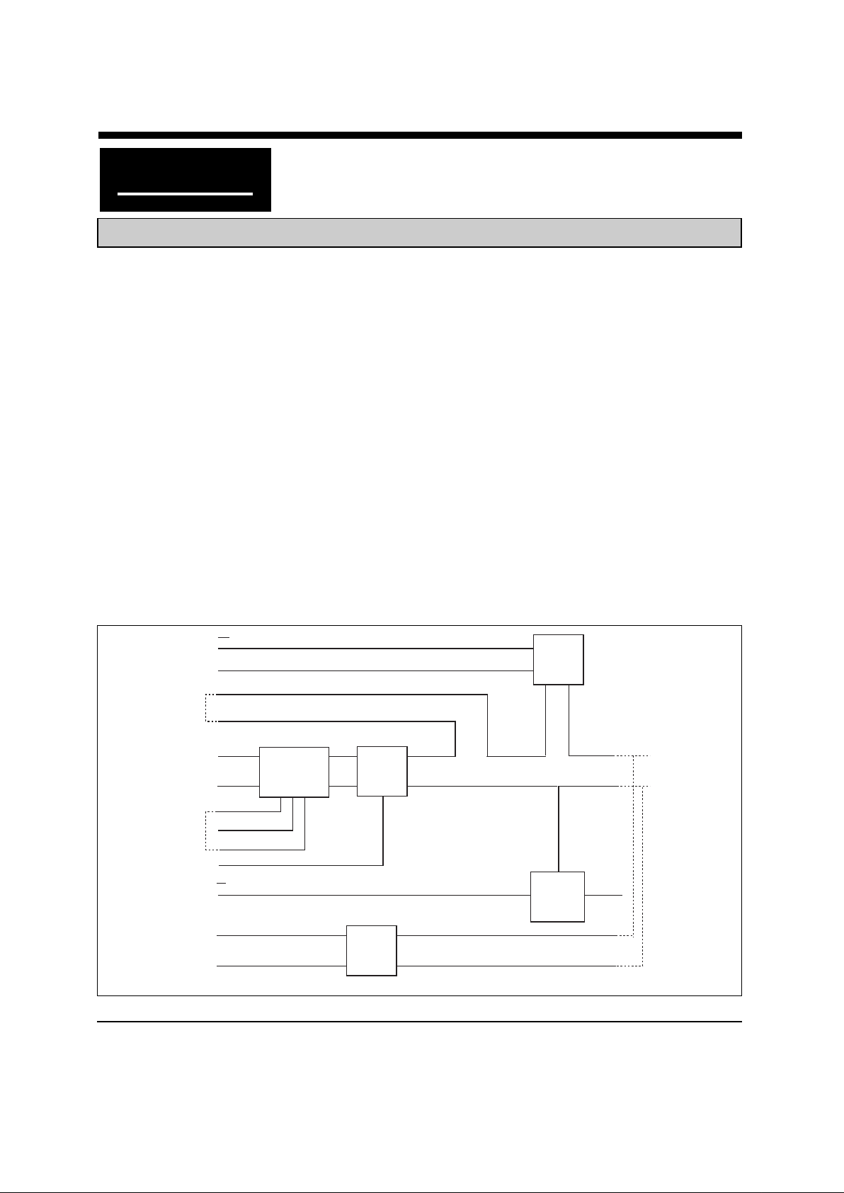
LINE
CURRENT
CIRCUIT
OH
RI
RING
DETECT
CIRCUIT
RING
TIP
T1
T2
GND
GND
GND
GNDGND
GND
GND
VCC
VCC
VCC
TINKLE
SUPPRESS
CIRCUIT
LS
BS
R1
R2
HOOK-
SWITCH
CONTROL
D2
WG1
LINE
TRANSFORMER
RET1
RET2
RET3
D1
BLOCK DIAGRAM
Description
Xecom's XE1000 provides a single hardware platform for telecom products world-wide. You no
longer need a unique design to comply with the
PTT requirements of each country. The XE1000
provides 4000 volts isolation and, in conjunction
with some external straps or components, meets
the requirements of PTT's throughout the world.
Small size and low power drain make the XE1000
ideal for compact, power-limited applications. The
XE1000 covers just 1.3 square inches of board
space and consume just 2 milliamps from the
single +5 volt supply. The XE1000 includes ring
detect circuitry , off hook control and bell tinkle
suppression for use in the UK.
Features
• Meet World-Wide PTT requirements
(external components may be required)
• 4000 Volts RMS isolation
• BABT Certified
• Small Size (1.05" x 1.25" x 0.40")
• Low Power (typical on-line; 10 milliWatts)
• PSTN and PBX Compatible
• Ring Detection
• Hookswitch Control
• Bell Tinkle Suppression Control (XE1000)
• FCC Part 68 Compliant
XECOM (2) XE1000
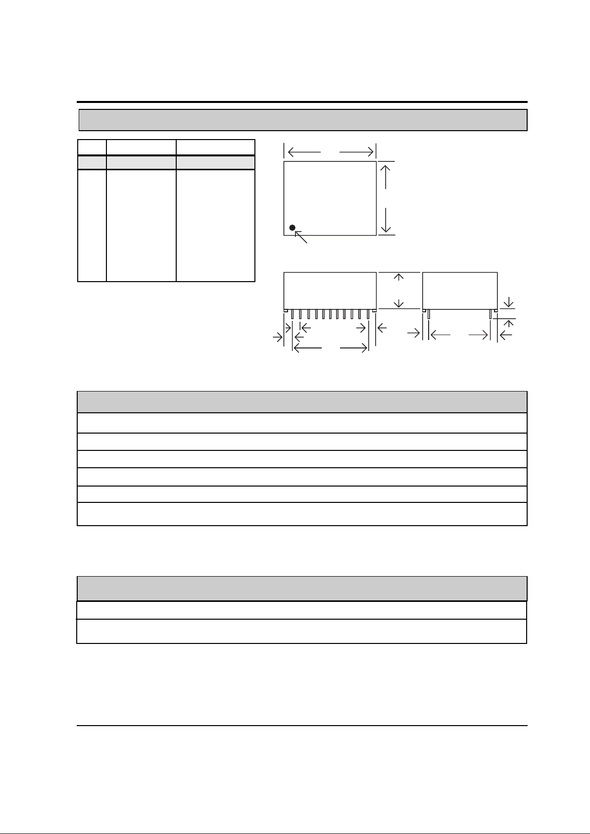
XE1000 Mechanical Specifications
A
B
Denotes Pin 1
C
D
G
G
E
F
H
H
J
Pin dimensions .025 inches (.635 mm) square
Recommended hole size .056 inches (1.42 mm)
INCHES METRIC(MM)
DIM MIN MAX MIN MAX
A 1.250 1.270 31.75 32.26
B 1.053 1.073 26.75 27.25
C 0.384 0.404 09.75 10.25
D 0.896 0.916 22.75 23.25
E 0.990 0.010 25.15 25.65
F 0.100 0.200 03.18 05.08
G 0.074 0.084 01.88 02.13
H 0.115 0.135 02.92 03.43
J 0.090 0.110 02.29 02.79
ABSOLUTE MAXIMUM RATINGS*
SUPPLY VOLTAGE - Vcc +7.0 Volts
DC INPUT VOLTAGE -0.6 Volts to +6.5 Volts
STORAGE TEMPERATURE RANGE -25° C TO +100° C
LEAD TEMPERATURE(Soldering, 10sec) 300° C
OPERATING TEMPERATURE RANGE 0 TO 70° C
*Exceeding these values may result in permanent damage to the device.
Symbol Parameter Min Typ Max Units Comments
Vcc Supply Voltage 4.5 5.0 5.5 Volts
Icc Supply Current 2.0 6.0 mA On-Line
Power Supply Characteristics
(TA = 0 - 70°C, Vcc = 5v ±10%)
XECOM (3) XE1000
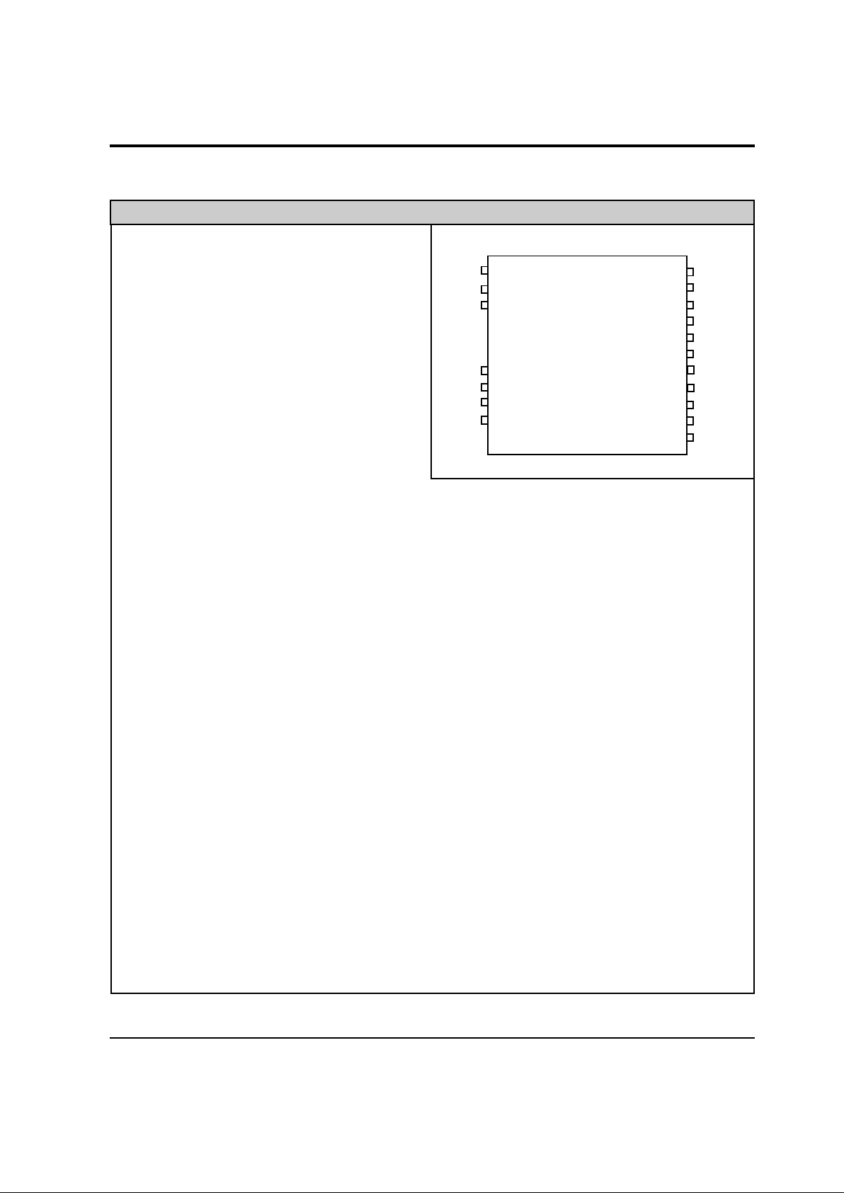
XE1000 Pin Configuration & Descriptions
1 /LS Active low, "Line Short" is used
during pulse dialing to short the
line for Tinkle Suppression in the
UK. This line must be held to at
least 4.0 volts to disable the Line
Short.
2 Vcc Vcc is the +5 volt supply voltage
input.
3 /RI This active low, open collector
output provides a pulse train at
twice the ring frequency present
on tip and ring.
4-6 — No Pin
7 T1 The positive input/output for differential analog signals.
8 OH Active low, the on-hook signal places the XE1000 in the on line state. It is pulsed in
combination with LS to provide pulse dialing.
9 GND Ground reference voltage for all control signals.
10 T2 The negative diff erential input/output for analog signals.
11 — No Pin
12 R1 R1 provides the Tip connection to the ring detect circuitry.
13 R2 R1 provides the Ring connection to the ring detect circuitry.
14 RET1 RET1 provides a 600 ohm line match when tied to Pin 17, RET3.
15 RET2 RET2 provides a custom line impedance match when connected to Pin 17, RET3, via
an external RC network.
16 WG1 Normally this pin is tied to Pin 20 but provides a connection for the billing tone filter
when required for homologation.
17 RET3 This pin is used in conjunction with pin 14 or 15 to provide matching line impedance.
18 D1 Normally this pin is tied to Pin 19, Ring, but provides a connection for the billing tone
filter when required for homologation.
19 Ring This Ring signal pro vides one of the two wires f or connection to the telephone network.
20 D2 Normally this pin is tied to Pin 16 but provides a connection for the billing tone filter
when required for homologation.
21 BS This wire provides the bell shunt connection for the UK, blue wire.
22 Tip The Tip signal provides half of the two-wire connection to the telephone network.
PIN NAME DESCRIPTION
122
221
320
19
18
17
716
815
914
10 13
12
TIP
BS
D2
RING
D1
RET3
WG1
RET2
RET1
R2
R1
/LS
Vcc
/RI
T1
/OH
GND
T2
XE1000

XECOM (4) XE1000
Parameter Min Typ Max Unit Description
Transmit Insertion Loss 1.0 2.0 4.0 dB Loss between transmit signal input and
telephone line signal at 1000 hz with
600 ohm line termination.
Receive Insertion Loss 1.0 2.0 4.0 dB Loss between telephone line input and
receive signal at 1000 hz with 600 ohm
line termination.
Line Matching Impedance 420 ohms Input impedance on T1/T2 required to
match a 600 ohm telephone line. See
Application note beginning on page 5
to match a Complex impedance such
as UKA.
Total Harmonic Distor tion 72 76 dB Level of signal distortion caused by the
XE1000 across the voice bandwidth.
Ring Detect Sensitivity 20 150 VRMS Ring signal levels detected as a valid
ring. Limits may be altered by modem
configuration.
Ring Indicate Output Voltage 4.2 Volts Signal level on RI when a valid ring sig-
nal is detected.
Line Holding Current 10 20 120 Mamps DC current supplied by the telephone
line.
Hook-Switch Control Voltage Voltage required to set hook-switch.
On-Hook 2.0 3.0 Volts
Off-Hook 0.2 0.5 V olts
Hook-Switch Control Current Current required to drive hook-switch.
On-Hook 0 Mamps
Off-Hook 5 Mamps
Line Short Control Voltage
Voltage Required to set Line Short relay
Active 0.2 0.8 Volts
Inactive 4.0 4.5 V olts
XE1000 Electrical Specifications

XECOM (5) XE1000
Country Configurations Application Note
o
o
o
o
o
o
o
o
o
o
o
o
o
o
o
o
o
o
22
21
20
19
18
17
16
15
14
13
12
1
2
3
7
8
9
10
+5V
RI
OH
LS
Vcc
RI
T1
OH
GND
T2
TIP
BS
D2
RING
D1
RET3
WG1
RET2
RET1
R2
R1
XE1000
R1
TXA1
Rin
Mute
TXA2
C1
D1
D2
Modem
Analog
Front-End
Bell Shunt
Tip
Ring
L1
C3
J4
R2
C2
R3
J1
J2
J3
R7
R5
R6
R4
D3
D4
VR1
J5
Figure 1: XE1000 Application Schematic
This application note shows how the XE1000 can
be used to connect with telephone networks in
Europe, North America and Japan. It includes the
schematic, parts list, and configuration table.
Only the XE1000 is this flexible. The addition of a
few external components permits this product to
meet a variety of telephone network regulations.
The adaptability of the XE1000 eliminates the
need for unique DAA's for each country.
The XE1000 includes ring detection and switch
hook control while maintaining the necessary isolation from the telephone network. The XE1000
also includes the tinkle suppression relay used in
the United Kingdom. The XE1000 is BABT approved.
The following pages illustrate ho w the XE1000 can
be configured for many countries.
Figure 1: An application schematic which includes all the circuitry required to meet the requirements of the listed countries. Component
usage and values vary with the country of installation as shown in Figure 3.
Figure 2: Country configurations for most of the
major market countries. Each column shows the
external components required to meet the individual country's telecom requirements.

XECOM (6) XE1000
Figure 2: Country Configurations
UK(A) UK(B)* USA Italy Japan Germany
R1
680 OHMS 420 OHMS 420 OHMS 420 OHMS 420 OHMS 820 OHMS
R2
560 OHMS OUT OUT OUT OUT OUT
R3
OUT OUT OUT OUT OUT 10 KOHMS
R4
OUT OUT OUT O OHMS OUT OUT
R5, R6
OUT OUT OUT OUT OUT 10 OHMS
R7
56 KOHMS 56 KOHMS 56 KOHMS 56 KOHMS 56 KOHMS 56 KOHMS
C1
OUT 6.8 nFd 6.8 nFd 6.8 nFd 6.8 nFd 33 nFd
C2 100 nFd
OUT OUT OUT OUT OUT
C3
OUT OUT OUT OUT OUT 0.022 uFd
L1
OUT OUT OUT OUT OUT 5 mH
VR1
OUT OUT TPB270B OUT TPB270B OUT
D1, D2
4.7 V olts 4.7 V olts 4.7 V olts 4.7 V olts 4.7 V olts 4.7 Volts
D3, D4
OUT OUT OUT 10 Volts OUT OUT
J1 IN
OUT OUT OUT OUT
IN
J2 IN
OUT OUT OUT OUT OUT
J3
OUT OUT OUT OUT OUT
IN
J4 IN IN IN IN IN
OUT
J5 IN IN IN
OUT
IN IN
UK(B) provides a 600 line termination; UK(A) terminates the line with a complex impedance and
is the preferred termination.
"OUT" indicates the component should not be installed for that application
"IN" indicates the component is required for the application
The part number shown for VR1 is manufactured by SGS Thompson
Notes on XE1000 Configuration:

XECOM (7) XE1000
US Telephone Line Connection Information
The following information describes the requirements for connecting equipment to the telephone network in
the United States. For similar inf ormation for other countries contact the regulatory agency in that country .
When developing a product to be connected to the telephone line, it is necessary for the equipment to be
approved by the appropriate governmental agency . In the US this agency is the Federal Communications
Commission (FCC). The FCC evaluates the product to ensure it meets all specifications, thereby
protecting the telephone system from damage and the user from high voltage transients (such as lightning
strikes) on the telephone line. The DAA performs an essential function in meeting these requirements.
The XE1000 meets or exceeds all FCC Part 68 requirements for hazardous voltage, surge protection and
leakage current. If the system transmits data, or DTMF tones on the telephone line, the user must meet
basic FCC requirements for maximum transmission levels of out of band energy and billing delay. Full
details may be obtained from the FCC under FCC P art 68 Rules and Regulations, or in Title 47 of the Code
of Federal Regulations, however the basic requirements are as follows:
1. Maximum Transmit Level
For the normal “permissive” (standard) telephone line , equipment which transmits data (such as a modem)
must not exceed a transmission level of -9 dBm.
2. Out of Band Energy
Data equipment must not transmit “out of band” energy on the telephone line which exceeds the following
limits:
Frequency Range Max. Power
200Hz to 3990Hz -9 dBm
3990Hz to 4005Hz -27 dBm
4005Hz to 16kHz -16 dBm
8kHz to 94kHz -47 dBm
86kHz to 270kHz -46 dBm
270kHz to 6MH -6 dBm
For modem applications, the out of band energy limit is normally ensured by the transmit filter in the modem
circuitry .
3. DTMF T ransmission Level
If the system is capable of DTMF dialing, the maximum DTMF transmission le v el m ust be less than 0 dBm
averaged over a 3 second interval.
4. Billing Delay
A delay of 2 seconds or greater is required after “off hook” and before any information is transmitted. This
is required to ensure that billing information may be exchanged betw een telephone company central offices
without interference.
The XE1000 user must certify to the FCC that the final system meets the requirements of Part 68 which
include the criteria above as well as the high voltage protection provided by the DAA. This is generally
accomplished through an independent testing lab which tests the System and submits the proper
paperwork to the FCC for approval.

XECOM (8) XE1000
Devices sold by XECOM are covered by the warranty provisions appearing in its Terms of Sale only.
XECOM makes no warranty, express, statutory, implied, or by description regarding the information set
forth herein, or regarding the freedom of the described devices from patent infringement. XECOM
makes no warranty of merchantability or fitness for any purposes. XECOM reserves the right to discontinue production and change specifications and prices at any time and without notice. This product is intended for use in normal commercial applications. Applications requiring extended temperature range,
unusual environmental requirements, or high reliability applications, such as military, medical life-support
or life-sustaining equipment, are specifically not recommended without additional processing and authorization by XECOM for such application.
Xecom assumes no responsibility for the use of any circuitry other than circuitry embodied in a Xecom
product. No other circuits, patents, or licenses are implied.
Xecom's products are not authorized for use as Critical Components in Life Support Devices or Systems.
Life Support Devices or Systems are devices or systems which, (a) are intended for surgical implant into
the body , or (b) support or sustain life, and whose f ailure to perf orm, when properly used in accordance with
instructions provided in the labeling, can be reasonably expected to result in significant injury to the user.
A Critical Component is any component of a life support device or system whose failure to perf orm can be
reasonably expected to cause failure of the life support device or system, or to affect its safety or
effectiveness.
Life Support Policy
Terms of Sale
Copyright, Xecom © 1997
While Xecom, Inc. has made e v ery effort to ensure that the information presented here is accurate, Xecom
will not be liable for any damages arising from errors or omission of f act. Xecom reserves the right to modify
specifications and/or prices without notice. Product mentioned herein are used for identification purposes
only and may be trademarks and/or registered trademarks of their respective companies.
Xecom Inco rporated
374 T urquoise Street, Milpitas, CA 95035
Ph:408-945-6640 * Fax:408-942-1346 * E-Mail: info@xecom.com
xecom
 Loading...