

Page 1

2-Wire/4-Wire Telephone Line Interface
XE0204
July 2000
Description
The XE0204 provides a common telephone interface
for networks integrating two and four-wire telephone
connections. The XE0204 supplies two and four wire
leased line connections, and complies with FCC Part
68 Rules for 2-wire connections to the public switched
network.
The XE0204 supports voice, data and fax transfer at
speeds to 14,400 Bits Per Second, V.32bis data transfer
over two wires and V.33 data transfer over four wires.
The XE0204 is a complete DAA in a compact package.
It includes the telephone line transformers, loop current
holding circuit, ring detection, switch hook, two-to-four
wire convertor and four-wire switch. The small size of
the XE0204, just 1.5 square inches, allows the XE0204
to be used in most any application requiring connection
to the telephone network.
Features
* Small Size 0 1.5” x 1.08” 0.42”
* FCC Part 68 Compliant
* Integral Ring Detection
* Integrated Switch Hook
* Switchable between two-wire and four-wire lines
* Integral two-to-four wire convertor
* Integrated telephone line transformers
* 1500 volt isolation barrier between the telephone line
and host equipment
* Supports both dial-up and leased line applications
* Supports 14,400 BPS data transfer; V.32bis (2-wire),
V.33 (4-wire)
* Operates on a single +5 Volt supply
* Standard Operating Temperature Range 0C to 70C
Optional operating range, -40C to 85C available
XE0204 Block Diagram
OH
XMIT
RCVR
/4Wire
4 Wire
Switch
2 to 4 Wire
Convertor
Telephone
Line
Transformer
Loop
Current
Holding
Circuit
/RI
Telephone
Line
Transformer
XECOM (1) XE0204
Hook
Switch
Tx Tip
Tx Ring
Ring
Detect
Rx Tip
Rx Ring
Page 2
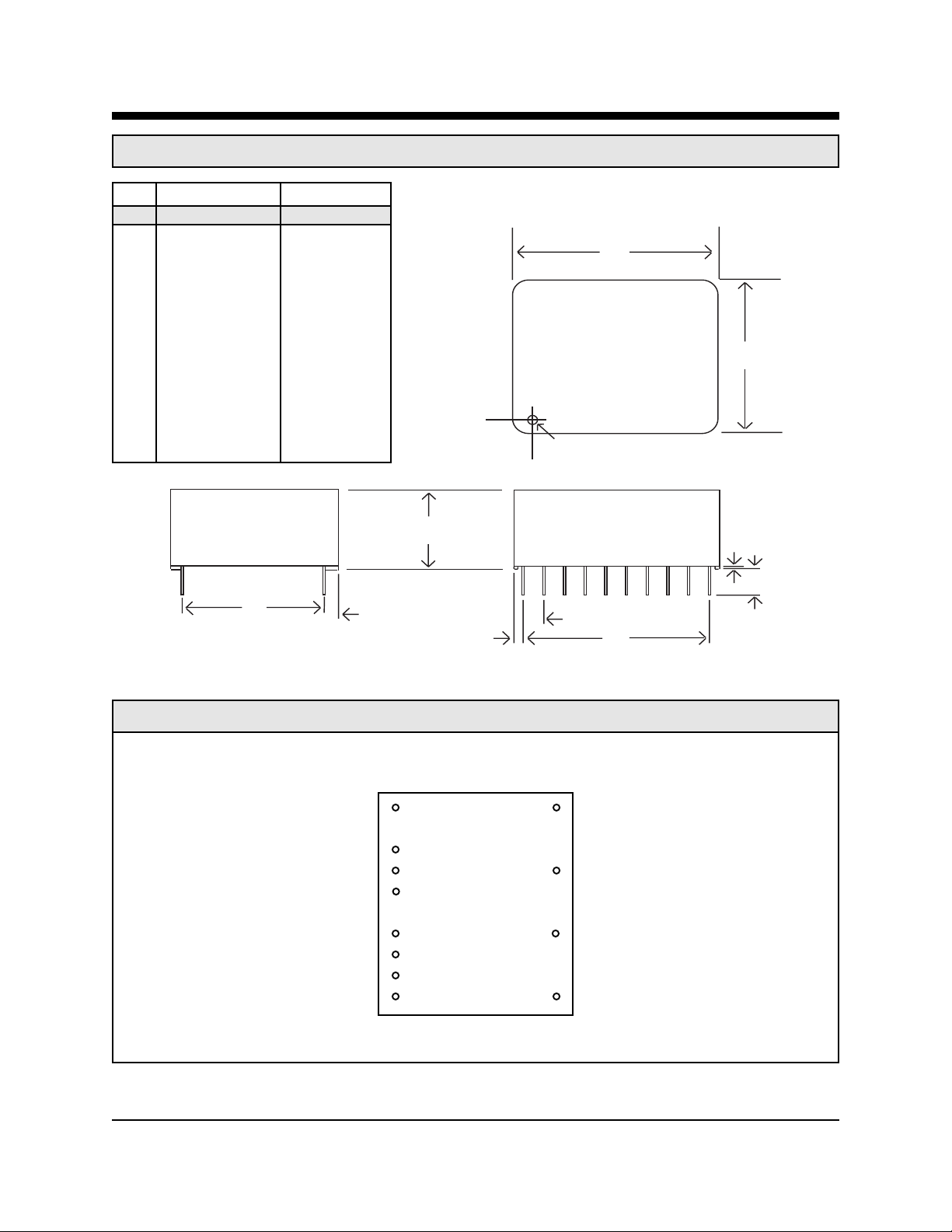
XE0204 Mechanical Specifications
Inches Millemeters
Dim Min Max Min Max
A 1.480 1.520 37.59 38.61
B 1.060 1.100 26.92 27.94
C 0.420 0.430 10.67 10.92
D 0.890 0.910 22.61 23.11
E 0.890 0.910 22.61 23.11
F 0.125 - 3.18 G 0.040 0.060 1.02 1.52
H 0.290 0.310 7.37 7.87
J 0.090 0.110 2.29 2.79
K 0.020 0.025 0.51 0.64
A
B
Denotes Pin 1
D
XE0204 Pin Configuration
VCC 1 20 TxTip
RCVR 4 17 TxRing
XMIT 5
OH 7 14 RxTip
/4Wire 8
N/C 9
Gnd 10 11 RxRing
C
G J
H
XE0204
(Top View)
/RI 3
K
F
E
XECOM (2) XE0204
Page 3

XE0204 Pin Configuration
Pin Name Description
1 VCC VCC supplies +5 Volts power to the XE0204
3 /RI Ring Indicate, output, active low, TTL. /RI indicates the XE0204 is receiving a ring signal. /RI remains
low for the duration of each ring.
4 RCVR RCVR acts as the analog output for signals recevied from the telephone line by the XE0204. In two wire
mode the received signal is placed on RCVR by the 2-to-4 wire convertor. In four wire mode the
received signal comes directly from the receive phone line pair.
5 XMIT XMIT provides the analog input to the XE0204 for signals to be transmitted onto the telephone line. In
two wire mode the signal is passed to the 2-to-4 wire convertor. In four wire mode the signal goes
directly the transmit phone line pair.
7 OH Hookswitch relay control. A high on OH closes the internal relay and connects the equipment to the
telephone line. OH must be forced high to maintain a 2 wire or 4 wire leased line.
8 /4Wire /4Wire is an active low input to the XE0204 which selects four wire operation. If pin 8 is open or driven
high, two wire mode is selected.
9 N/C No Connection
10 Gnd Gnd provides the ground reference connection to the XE0204.
11 RxRing RxRing provides the Ring connection to the receive pair of the four wire phone line. RxRing is not used
for two wire connections. RxRing has 1500 volts isolation from the rest of the circuitry. This isolation
must be preserved throughout the system.
14 RxTip RxTip provides the Tip Connection to the receive pair of the four wire phone line. RxTip is not used for
two wire connections. TxTip has 1500 volts isolation from the rest of the circuitry. This isolation must
be preserved throughout the system.
17 TxRing TxRing provides the Ring Connection to two wire lines as well as to the transmit pair of four wire phone
lines. TxRing has 1500 volts isolation from the rest of the circuitry. This isolation must be preserved
throughout the system.
20 TxTip TxTip provides the Tip Connection to two wire lines as well as to the transmit pair of four wire phone
lines. TxTip has 1500 volts isolation from the rest of the circuitry. This isolation must be preserved
throughout the system.
XECOM (3) XE0204
Page 4

XE0204 Electrical Specifications (VCC= +5V + 10%, Ta = 0C to 70C)
Parameter Conditions Min Typ Max Units
Power Supply Current 4-Wire Operation 10 16 mA
Transmit Insertion loss 2-Wire line, 1000 Hz, 600 Ohm line -0.5 0 0.5 dB
Receive Insertion Loss 2-Wire line, 1000 Hz, 600 ohm line -0.5 0 0.5 dB
4-Wire line, 1000 Hz, 600 ohm line 0.8 3.0 dB
Telephone Line Impedance At 1800 Hz, (2 and 4 wire Lines) 540 6 00 660 Ohms
Coupler Match input Output impedance driving RCVR in four- 531 536 541 Ohms
Impedance wire mode
Transmit Input Impedance At 1800 Hz 8 10 12 KOhms
Receive Output Impedance 2 Wire mode, 1800 Hz 10 100 Ohms
Transhybrid Loss 2-wire mode, 1 KHz, 600 ohm line 15 21 dB
Ring Detect Sensitivity T ype B Ringer 38 150 Vrms
Ring Indicate Output Ring Voltage present on Tip and Ring 0.2 0.5 Volts
Hook Switch Control Voltage ON: (off-hook) 4.0 Volts
OFF: (on-hook) 0.8 Volts
Hook Switch Control Current Off-Hook 0.5 mA
/4WIRE Switch 2-Wire 4.0 Volts
4-Wire 0.8 Volts
Loop Current, Tx Pair Off-hook 0 100 mA
Loop Current, Rx Pair 4-Wire Line 0 mA
XE0204 Absolute Maximum Ratings
Supply Voltage - VCC +6.5 Volts
Storage Temperature -25OC to +85OC
Operating Temperature Range 0OC to +70OC
Maximum Lead T emperature 260OC
(soldering 2 seconds per wave)
XECOM (4) XE0204
Page 5

XE0204 Typical Connection Diagram for a 2-Wire, Dial-up Line
+5 Volts
XE0204
Modem Analog
Front End RJ11
/Ring
Receive
Transmit
OHRLY
VCC TxTIP
/RI
RCVR TxRING
XMIT
OH RxTip
/4Wire
Gnd RxRing
10 ohms, 1/2 W
P3100SB
10 ohms, 1/2 W
Teccor
FerriteBead
FerriteBead
470 pFd
2600 Volts
470 pFd
2600 Volts
XE0204 Typical Connection Diagram for a 2-Wire, Leased Line
4
3
Modem Analog
Front End
/Ring
Receive
Transmit
OHRLY
+5 Volts
XE0204
VCC TxTIP
/RI
RCVR TxRING
XMIT
OH RxTip
/4Wire
Gnd RxRing
10 ohms, 1/2 W
P3100SB
10 ohms, 1/2 W
Teccor
FerriteBead
FerriteBead
470 pFd
2600 Volts
RJ11
4
3
470 pFd
2600 Volts
XECOM (5) XE0204
Page 6

XE0204 Typical Connection Diagram for a 4-Wire, Leased Line
+5 Volts
XE0204
Modem Analog
Front End RJ11
/Ring
Receive
Transmit
OHRLY
VCC TxTIP
/RI
RCVR TxRING
XMIT
OH RxTip
/4Wire
Gnd RxRing
10 ohms, 1/2 W
10 ohms, 1/2 W
10 ohms, 1/2 W
10 ohms, 1/2 W
Teccor
P3100SB
Teccor
P3100SB
FerriteBead
FerriteBead
FerriteBead
FerriteBead
470 pFd
2600 Volts
Recommended Parts
Reference Designation Recommended Part Number
Ferrite Beads TDK ACB2012L-120-X
4
3
RJ11
4
3
High Voltage Capacitors Panasonic ECKDRS471, 470 pfd, 2600 Volts
RJ11 Telephone Jack Stewart SS6446NF
XECOM (6) XE0204
Page 7

XE0204 FCC Instructions
When developing a product to be connected to the telephone line, it is necessary to use a circuit described as a Data Access
Arrangement (DAA) which is approved by the appropriate governmental agency. In the US, for example, this agency is the Federal
Communications Commission (FCC), while in Canada it is the Department of Communications (DOC). These agencies test and
approve the product to ensure that it meets their specifications, thereby protecting the telephone system from damage and
protecting the user from high voltage transients (such as lightning strikes) which may come down the telephone line.
The XE0204 has been designed to meet all FCC Part 68 requirements for hazardous voltage, surge protection and leakage current.
If the system developed transmits data, or DTMF tones on the telephone line, the user must certify that the signals transmitted meet
basic FCC requirements for maximum transmission levels, out of band energy and billing delay . Full details may be obtained from
the FCC under Part 68 of the FCC Rules and Regulations, or in Title 47 of the Code of Federal Regulations, however the basic
requirements are as follows:
1. Maximum Transmit Level
For the normal “permissive” (standard) telephone line, equipment which transmits data (such as a modem) must not exceed a
transmission level of -9 dBm.
2. Out of Band Energy
Data equipment must not transmit “out of band” energy on the telephone line which exceeds the following limits:
Frequency Range Max. Power
200Hz to 3990Hz -9 dBm
3990Hz to 4005Hz -27 dBm
4005Hz to 16kHz -16 dBm
8kHz to 94kHz -47 dBm
86kHz to 270kHz -46 dBm
270kHz to 6MHz -6 dBm
3. DTMF Transmission Level
If the system is capable of DTMF dialing, the maximum DTMF transmission level must be less than 0 dBm averaged over a 3
second interval.
4. Billing Delay
A delay of 2 seconds or greater is required after the time the XE0204 is taken “off hook” and before any information is transmitted.
This is required to ensure that billing information may be exchanged between telephone company central offices without
interference.
The user of the XE0204 must certify to the FCC that the final system meets the requirements of Part 68 which include the criteria
above as well as the high voltage protection provided by the XE0204. This is generally accomplished through an independent
testing lab which tesst the System and submits the proper paperwork to the FCC for approval. Since the X0204 already complies
with FCC Part 68 rules, this is a relatively simple proces
s.
XECOM (7) XE0204
Page 8
Terms of Sale
Devices sold by XECOM are covered by the warranty provisions appearing in its Terms of Sale only. XECOM
makes no warranty, express, statutory, implied, or by description regarding the information set forth herein, or
regarding the freedom of the described devices from patent infringement. XECOM makes no warranty of
merchantability or fitness for any purposes. XECOM reserves the right to discontinue production and change
specifications and prices at any time and without notice. This product is intended for use in normal commercial
applications. Applications requiring extended temperature range, unusual environmental requirements, or high
reliability applications, such as military, medical life-support or life-sustaining equipment, are specifically not
recommended without additional processing and authorization by XECOM for such application.
Xecom assumes no responsibility for the use of any circuitry other than circuitry embodied in a Xecom product.
No other circuits, patents, or licenses are implied.
Life Support Policy
Xecom's products are not authorized for use as Critical Components in Life Support Devices or Systems.
Life Support Devices or Systems are devices or systems which, (a) are intended for surgical implant into the body,
or (b) support or sustain life, and whose failure to perform, when properly used in accordance with instructions provided in the labeling, can be reasonably expected to result in significant injury to the user.
A Critical Component is any component of a life support device or system whose failure to perform can be reasonably expected to cause failure of the life support device or system, or to affect its safety or effectiveness.
Copyright, Xecom © 2000
While Xecom, Inc. has made every effort to ensure that the information presented here is accurate, Xecom will not
be liable for any damages arising from errors or omission of fact. Xecom reserves the right to modify specifications
and/or prices without notice. Product mentioned herein are used for identification purposes only and may be trademarks and/or registered trademarks of their respective companies.
Incorporated
Xecom
374 Turquoise Street, Milpitas, CA 95035
Ph:408-945 -6640 Fax:408 -942-1346
Email: info@xecom.com
XECOM (8) XE0204
 Loading...