

Page 1

Cypress USB to Serial Quick Start and User Guide
Quick Start Developers Guide
This is a simple description of the steps needed to
use the USB to serial reference design.
1. Setup Development Kit
The first step is to setup the necessary development
kit. The development kit that will be used will
depend on the choice of microcontroller. Simply
follow the installation instructions that come with the
development kit.
2. Customize Firmware
The next step is to customize the USB to serial
firmware to fit your application. This will include
changing the value of the vendor and product ID in
the device descriptor. Other changes may also be
necessary in the firmware if the application requires
any specialized use of handshaking signals. Please
refer to the design notes included in this package for
an explanation of the firmware and where and how to
make changes to it.
3. Connect Serial Device to
Development Kit
Interface the USB to serial reference design with the
existing serial device. A description of pin
assignments and how to interface the devices is
given in the hardware section of the design notes.
4. Enumerate Device
Connect the development kit, with the firmware
running, to the USB port on the computer and make
sure that it enumerated properly. This can be
verified by opening the device manager and looking
for a Human Interface Device that was created.
5. Test Firmware
Use the HidCom test application to test the device.
This application begins by detecting the USB to
serial device and sets the proper communication
settings for it. At that point you can send and receive
data, set and clear handshaking signals and read the
state of the handshaking signals on the device.
6. Create INF file
After the firmware has been verified to function
correctly, it is then necessary to create an INF file so
that the enumeration process calls on the virtual port
emulation driver. The HidCom test application has a
button that is used to automatically generate an INF
file that corresponds to the VID and PID which it is
currently communicating with.
7. Install the Com Port emulation driver
Install the Cypress COM port emulation driver by
simply running the HidComInst executable that
comes with this package. To verify that the driver
was loaded correctly you must look at the device
manager once again. This time check under COM
ports and make sure that the Cypress Virtual Port
has appeared.
8. Run application
Run the software application that is supposed to
work with your device. Connect it to the COM port
associated with the virtual COM port. The virtual
COM port is usually labeled with the number of the
next unused COM port. For example if you have two
ports on your system which are labeled COM1 and
COM2 then the virtual COM port will be COM3.
Cypress Semiconductor Corporation • 3901 North First Street • San Jose • CA 95134 • 408-943-2600
July 09, 2001
Page 2
USB to Serial Quick Start and User Guide
USB to Serial Quick Start Demo Guide
1. Purpose
This section is intended to provide a step by step guide to getting the USB to Serial reference design up and
running with a demo. This will provide the user with instant verification of the USB to Serial system functionality
including driver, firmware, and hardware.
2. Installing the Driver
2.1 At the DOS prompt make sure the current working directory contains HidCOMInst, the INF file, and the
drivers. These are all located in the Apps_and_Drivers folder of the reference design. Simply type
“hidcominst”. Nothing will appear to happen however this will remove any previous USB to Serial
information and then copy the driver and INF file to the proper directories. The system is now ready for
the device to be plugged in.
3. Plugging in the device
Under Win2K the driver should be located automatically so the following sequence doesn’t apply. Therefore
Win2K users should skip to section 3.5.
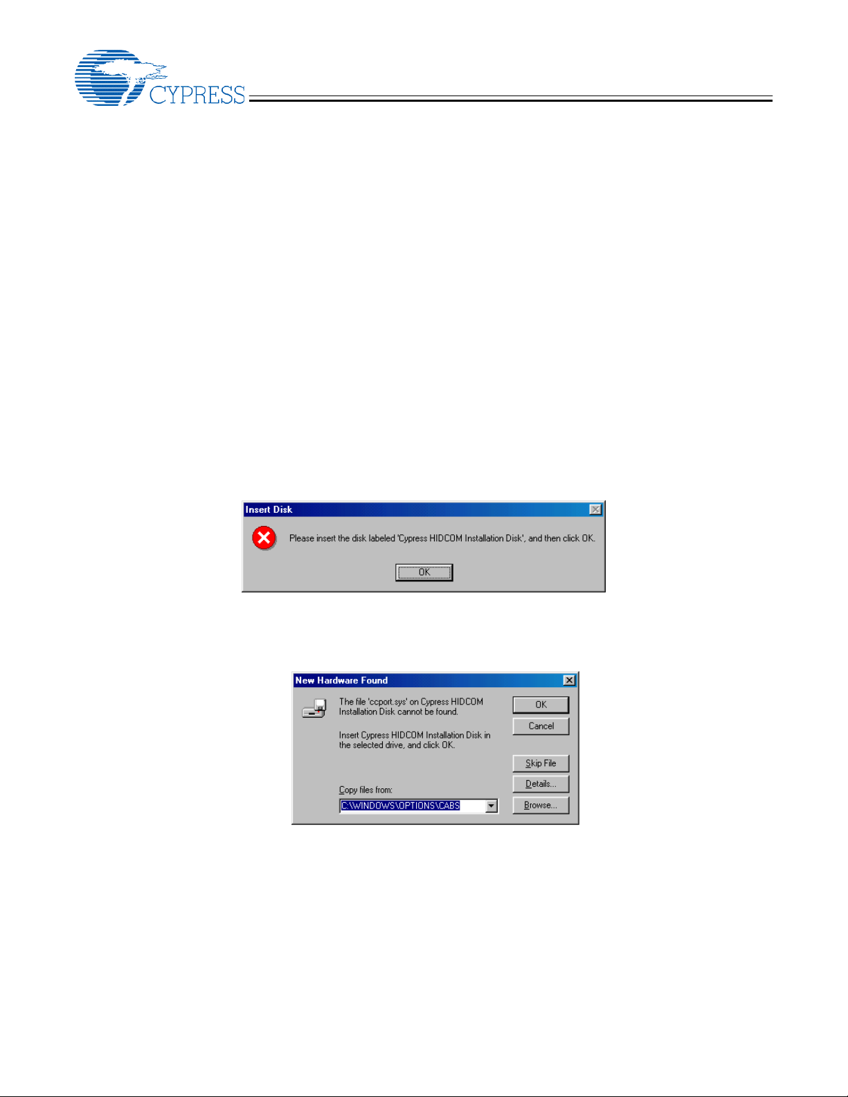
3.1 Once the device has been plugged in the following window will appear. Select OK.
3.2 Next the system will try and locate the driver. In the New Hardware Found window Click Browse.
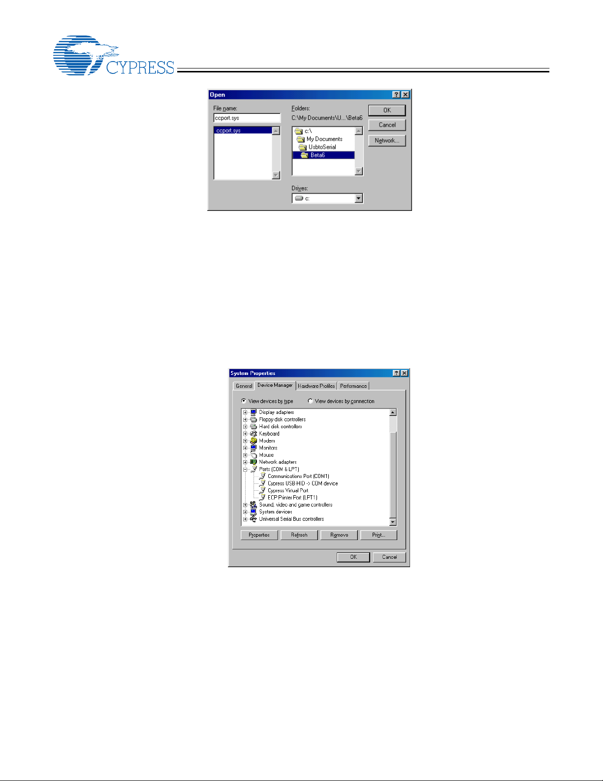
3.3 In the window below select the location containing the Ccport.sys driver. Note: The default location in the
reference design is in the Apps_and_Drivers folder, not the location shown below.
2
Page 3
USB to Serial Quick Start and User Guide
3.4 After the correct location has been selected, click OK. Then click OK in the New Hardware Found
window.
3.5 After a few seconds the device should finish enumerating. Verify that the device enumerated properly by
checking the Device Manager.
3.5.1 On the desktop right click My Computer
3.5.2 Click Properties
3.5.3 In Win98 select the Device Manager Tab: In Win2K select the Hardware Tab and then click
Device Manger
3.5.4 Check the Ports section and verify that the Cypress Virtual Port has appeared as below.
4. Demonstration using Serial Test
Serial Test provides the user with a visual indication that the USB to Serial system is functioning properly. Serial
Test is an application that performs a loopback test over two ports, in this case the Cypress Virtual Port and a real
Serial Port. It enables a given test vector to be transmitted and received between the two ports. The following
steps will demonstrate data being looped back between these ports. For further information on Serial Test please
refer to the Application’s User Guide.
3
Page 4

USB to Serial Quick Start and User Guide
4.1 Plug in the USB to Serial device. Now attach an RS-232 Null Modem cable between the USB to Serial
device and a COM port on the same PC.
4.2 Open up serial Test. The following screen will appear. Select one port as the Cypress Virtual Port, and
the other as whichever COM port you attached the RS-232 cable to. Then click on Open Ports. Note: if
unsure which port is the Cypress Virtual Port, simply unplug USB to Serial, click Refresh and see which
port option disappeared.
4.3 Upon opening the ports, two windows will open up as shown below (Move the first window aside to see
the second). Click Hardware flow control in each window and then click Set Config in each window. Now
communication is ready to take place.
4.4 To transmit data, click the Tx Enable box in the top left corner of one of the windows. Data will begin to
flood the Received Data box in the other window as shown below.
4
Page 5

USB to Serial Quick Start and User Guide
4.5 To reverse direction uncheck the Tx Enable and check it in the other box. Again, data will start to flood
the other Received Data box as shown below. Note: If working with half duplex (CY7C64013 or
CY7C63743) be sure that both Tx Enables are not checked at the same time.
4.6 When done, uncheck the Tx Enable, then click Close Ports on the opening screen.
5. Trouble Shooting
5.1 If the Driver isn’t loading properly:
5.1.1 If a previous version of USB to Serial has been installed, reboot the PC and try again.
5.1.2 Try running HidCOMInst again, make sure USB to Serial is unplugged first.
5.2 If Serial Test isn’t receiving data:
5.2.1 Make sure a null modem cable is used.
5.2.2 Make sure both port configurations match.
5.2.3 Make sure Hardware flow control is set accordingly.
5.2.4 Make sure Set Config Needed isn’t flagged, if so click Set Config.
5.3 If you are using Windows XP
Under some circumstances, Windows XP fails to load the HIDCOM driver, and instead loads the Windows
HID driver for the device. In this case, follow the steps below to force Windows to use the HIDCOM driver:
5.3.1 Open up the device manager.
5.3.2 Find the Human Interface Device key related to USB to Serial and right click on it.
5.3.3 Select Update Driver
5.3.4 Select “Install from list from specific location” and click Next.
5.3.5 De-select “Search removable media”. Then select “Include this location in Search”.
5.3.6 Click Browse. Find the directory containing the Ccport.sys driver and click OK. It is located in the Apps_and_Drivers directory of the reference design.
5.3.7 Select “Don’t search, I will choose the driver to install”. Then click Next.
5.3.8 Select “Cypress USB-HID -> COM device” and click Next.
5.3.9 Windows will prompt you for the HIDCOM.sys driver. Click Browse and locate HIDCOM.sys (also located in the Apps_and_Drivers directory of the reference design) and click Next.
5
Page 6

USB to Serial Software Applications User Guide
1. Introduction
The purpose of this guide is to give a brief overview
of the three host applications provided with the USB
to Serial reference design.
• HidCOMInst
• HidCOMTest
• Serial Test
HidCOMTest and Serial Test are targeted at
firmware development and testing while HidCOMInst
is used for driver installation/uninstallation. This
guide will outline the fundamental purpose of each
program and then give a detailed description of how
to use it.
2. HIDCOMINST
USB to Serial Quick Start and User Guide
Running HidCOMInst does two things. First it goes
through and removes any registry entries, INF files,
or drivers related to USB to Serial. After the system
has been cleared of any possible previous USB to
Serial installs, it then copies the current INF file into
the …/INF directory and the related drivers into the
…/SYSTEM32/DRIVERS directory. (Please make
sure the system has been rebooted following any
previous installs of earlier USB to Serial driver
versions.) When it copies the INF file into the
corresponding directory it changes the name to
“oemX.inf”(X is an integer starting at zero).
HidCOMInst allows for five different parameters to
be passed in when executed. They are as follows:
-h Help Box
-u Uninstall HidCom device
2.1 Purpose
HidCOMInst is a simple DOS command line
application that copies the USB to Serial INF file and
the corresponding driver(s) into their proper
directories. It copies the INF file into the …/INF
directory and the corresponding driver(s) Ccport.sys
and/or HidCom.sys, into the
…/SYSTEM32/DRIVERS directory. Without running
this application, which installs the driver, the OS will
determine the device is a HID device and attempt to
load the HID driver instead of the USB to Serial
driver. Once this has been done the OS will not
prompt the user again for the USB to Serial Driver.
To load the USB to Serial driver at this point,
HidCOMInst should be run.
2.2 How to Use
HidCOMInst should be run before plugging in the
device. At the DOS prompt, make sure the current
working directory contains HidCOMInst, the INF file,
and the drivers. In general just typing “hidcominst” in
this working directory is all that is necessary.
However deviations from this must be taken if the
default INF file and or driver names have been
changed. Therefore, unless any name changes
have been made just type “hidcominst”. If name
changes have been made the “-d” and “-i”
parameters discussed below must be used.
-i <infname> Set .INF filename (defaults
to HidCom.inf)
-d <drvname> Set .SYS filename (defaults
to HidCom.sys)
-v Verbose
Note: When running HidCOMInst with the “-v”
parameter, the verbose may give several failure
warnings. Most of the time this is okay, these
warnings usually occur because the INF file covers
several different devices that may not be present on
the current system.
3. HIDCOMTEST
3.1 Purpose
HidCOMTest is an application used to test the USB
to Serial reference design with the standard HID
driver. This allows firmware development to be
isolated from the USB to Serial specific driver.
HidCOMTest can also be used to automatically
generate an INF file for a customer’s device with a
specific VID and PID.
6
Page 7

USB to Serial Quick Start and User Guide
3.2 How to Use
3.2.1 Setup
First make sure the USB to Serial driver isn’t loaded.
Do this by typing “hidcominst –u” at the DOS prompt
in the directory containing HidCOMInst. If the driver
was previously loaded this will uninstall it, if it wasn’t
loaded this won’t cause any problems. Now the
device is plugged in and should be able to be
enumerate as a HID only device. When the install
wizard comes up have it search the
Windows/System directory (or wherever the HID
driver is located). Verify it worked by looking in the
Device Manager - there should be two entries in the
HID section for USB to Serial (HID device, and HID
compliant device).
If it didn't install as a HID do a search on the INF
directory for oem0.inf, this file should have been
removed by running “hidcominst –u”. If it is still there
then the device will enumerate with the USB to Serial
specific driver instead of the HID driver so it needs to
be deleted. Delete it and then try again by plugging in
the device.
3.2.2 Communication
To use the application for performing full
communication, both TX and RX (half duplex), a
companion application such as hyperterminal or
Serial Test needs to be opened. HidCOMTest will
communicate with the virtual COM port while the
companion application should be configured to
communicate with the real COM port. Match all of
the configuration settings, then anything typed into
hyperterminal or transmitted from Serial Test should
appear in the Receive window of HidComTest and
vice versa; anything typed in Transmit of
HidComTest should appear in hyperterminal or
Serial Test.
Before attempting communication, be sure to
configure the proper baud rate, data bits, parity, and
stop bits for both ports. Once selected click the
“Send Config” button. At this point communication is
ready to take place.
Different check boxes are also provided to enable
DTR, RTS, and Reset.
3.2.3 Create INF Files
The “Write .INF” option allows the user to
automatically add their specific VID and PID into the
INF file without having to manually edit HidCom.INF.
This will customize the INF file for use with their
product.
The “Devices Found” window displays the VID and
PID of all HID devices connected to the system.
Select the corresponding USB to Serial device and
click the “Write .INF” button. This will create a
customized INF file by simply adding a few lines with
the specific VID and PID to the default HidCom.INF
file.
4. SERIAL TEST
4.1 Purpose
Serial Test is an application that allows the user to
perform simple loopback testing. In its most basic
form, Serial Test provides a means for displaying
received data or transmitting data on a specific COM
port. It can be used to open two ports on a single
machine (a cypress virtual port and a real COM port)
and perform both ends of the communication, or it
can be used to open one port and simply perform
half of the communication.
Serial Test has a known test vector of
“0123ABCDEFGHIJKLMNOPQRSTUVW XYZ” which
is transmitted. It also expects to receive this same
test vector on the other end. Any character that
deviates from this vector in the received data is
defined as one “Sync Loss”. Therefore Serial Test is
a simple way to verify the validity of the entire USB to
Serial system.
4.2 How to Use
4.2.1 Setup
Once open, Serial Test gives the option to open one
or two Serial Ports. If a loopback test is going to be
run with only the Serial Test application then open
two ports, the Cypress Virtual Port and a real COM
port. If Serial Test is going to be run with a
companion application such as HidCOMTest or
Hyperterminal then just open the single appropriate
port.
4.2.2 Configuration
After the ports have been opened all of the
appropriate configurations must be set before any
data can be transmitted or received. To do this,
configure all of the following options and then click
on the “Set Config” button:
Baud Rate
Hardware Flow Control
7
Page 8

USB to Serial Quick Start and User Guide
Stop Bits Word Length
Parity
Status information such as DSR, CTS, RI, etc, can
be monitored by checking the “Status polling
enabled” check box.
4.2.3 Communication
Once everything has been configured and the “Set
Config” button has been clicked, communication is
ready to take place. To transmit click the “Tx
Enable” check box. As long as this box is checked
transmission will continue; uncheck it to stop.
Another option for transmitting is to transmit a single
test vector at a time. When “Tx single Bytes only” is
checked and the “Tx Enable” is checked then the
test vectors won’t continuously stream out. Instead
they will have a delay in between transmissions.
Whenever communication takes place a Tx Rate
and an Rx Rate will be displayed in the
corresponding window. If at anytime communication
freezes then these values will drop to zero. All data
received will be displayed in the received data
window.
same way, turning it on and off should change the
DSR indicator in the other port.
4.2.4 Error Indicators
Serial Test provides four error indicators, RX
Overrun, Rx Overflow, Parity Error, and Framing
error. These error boxes are all latching so once
one of these occurs the checkbox will stay checked
until the “Rese Errors” button is clicked.
The RX overrun and RX overflow errors are related
to the OS and the COM port RX FIFO buffer
settings. If either of these errors occurs the error
isn’t firmware or USB to Serial Driver related and the
error can be discounted. The parity error and
framing errors are each related to firmware. Should
one of these errors occur, the timing of the TX
routine in the firmare must be examined.
To exit the application, don’t click on the “X”, instead
click on the “Close Port” button in the opening form
and then click “Exit or “X”.
If at any point configuration settings need to be
changed then the “Tx Enable” must first be
unchecked. Once the changes have been made
“Set Config” must be clicked before the changes will
take place. Once “Set Config” is clicked the “Set
Config Needed” indicator will be unchecked and
communication is ready to resume.
Serial Test also provides a DTR and RTS check box.
These will control the corresponding signal. The
user can check and uncheck the RTS box to perform
manual flow control. If flow control is enabled in the
device, this box should regulate whether data is
transmitted or not. The user can also monitor this
signal if Serial Test is run on two ports. Manipulating
RTS in one port should correspond to the CTS
indicator in the other port. The DTR signal works the
5. USB_to_Serial Example
5.1 Purpose
This is an example application written in VisualBasic,
illustrating communication between a USB-Serial
Bridge device and a user mode application written in
VB that uses the Windows HID driver in place of the
Cypress HIDCOM driver.
5.2 How to Use
The ReadMe file included with the application
provides instructions for the execution and
modification of this example.
8
 Loading...