

Page 1
MLX902xx Name of Sensor Rev Y.X 22/Aug/98 Page 1
US79 Series
CMOS Power Hall IC
US79 CMOS Power Hall IC Rev 3.0 23/Jan/01 Page 1
Features and Benefits
ESD Tolerance IC>7,000V
ESD Tolerance of Fan >15,000V
Built-in Reverse Voltage Protection
Built-in RFI Filter
Power Efficient CMOS and Power MOSFET Drivers allow 400mA without overheating
Built-in Zener Diodes Protect Outputs
Eliminates all Fan Components
Eliminate PC Board
5V and 12V Operation
High Sensitivity for switching symmetry
Locked Rotor Shutdown
Applications
Fan Sizes up to 90mm
Current Range up to 400mA
Ordering Information
Part No. Temperature Suffix Package Temperature Range
US79 K UA -40oC to 125oC
US79 K 8-Pin Narrow SOIC -40oC to 125oC
Description
The US79KUA is the most advanced Smart Fan
Control Hall IC. It is designed for 5V and 12V cooling
commutation. The chip contains many features to
allow survival in a harsh environment. The IC was
designed to eliminate all discrete components such
as capacitors, resistors, transistors, diodes, PC
board and associated labor, replacing US$0.25 to
US$0.35 in direct cost.
The K rating guarantees proper operation up to an
ambient temperature of 125°C. Hall IC circuitry and
power FET output provide a low power dissipation
cool chip.
Locked Rotor conditions are detected by the IC when
there is no motion for one second and will shut off
the motor drive for five seconds. Then, the IC will
turn on the drive current for one second. This
sequence continues indefinitely until the locked rotor
condition is fixed. This feature prevents overheating.
Maximum ambient temperature is determined by
driver power dissipation. For instance, at 125C
ambient, driver power cannot exceed 125mW or
250mA. Future versions will offer optional features.
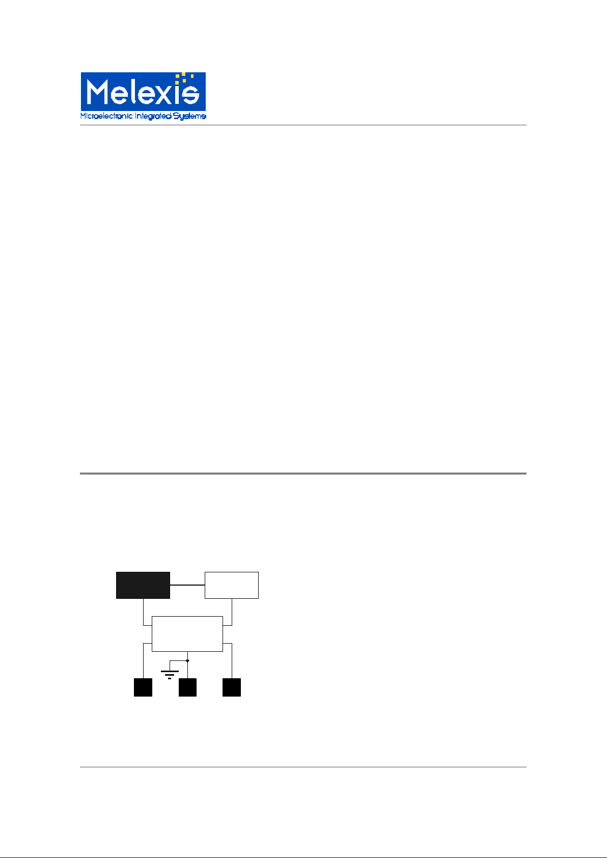
Functional Diagram
Voltage
Regulator
1 2 3
Hall Latch
Output 1 Output 2
Control and
Protection
GND
-+
Page 2
US79 Series
CMOS Power Hall IC
US79 CMOS Power Hall IC Rev 3.0 23/Jan/01 Page 2
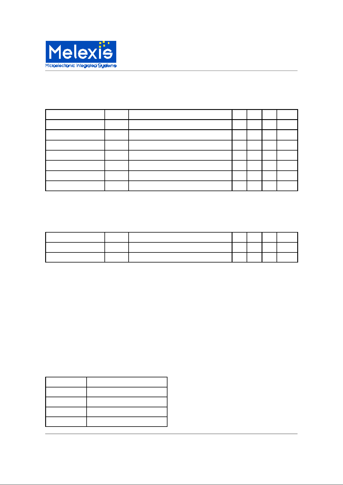
US79 Electrical Specifications
DC operating parameters: TA = 25 to 125oC, VDD = 5.0 to 12V unless otherwise specified.
Parameter Test Conditions Min Typ Max Units
Supply Voltage V
DD
Operating 3.7 - 18 V
Supply Current I
DD
Operating 1.2 2.0 4 mA
Output leakage I
LEAK
B<B
OP
- 1 10 µA
Output voltage V
OUT
B<B
HYS
- - 35 V
Output Saturation voltage V
DSS IOUT
= 150mA, VDD = 12V 400 600 mV
Output Saturation voltage V
DSS IOUT
= 350mA, VDD =12V 800 1100 mV
Output On resistance R
DDSS VDD
= 12V 1.34 Ω
Thermal resistance R
th
Operating 200 °C/Watt
US79 Magnetic Specifications
DC operating parameters: TA = 25 to 125oC, VDD = 5.0 to 12V unless otherwise specified. 1 mT = 10 Gauss.
Parameter Symbol Test Conditions Min Typ Max Units
Operate Point B
OP
Operating 3.0 6.0 mT
Release Point B
RP
Operating -6.0 -3.0 mT
Hysteresis B
HYS
Operating - 6.0 - mT
General Description
The US79 eliminates 16 solder joints, protects
against ESD, filters RFI emission caused by
switching of high currents, protects against voltage
surges, protects against locked rotor, operates at a
low temperature and is manufactured in an
Automotive IC factory.
Unique Features
Reverse voltage protection eliminates the need for a
diode. Reverse current flows through the coils and
the chip. Power dissipation is (2 * Istall/start * 0.7V).
Table 1 presents max temperature for each current.
Table 1
I
stall
/ I
start
TA Maximum Rev V Test
100mA 125°C
200mA 100°C
300mA 70°C
400mA 40°C
The IC tolerates >7000V ESD. When installed in the
fan, the windings increase the ESD tolerance to
>15000V eliminating the need for ESD concerns in
the finished fan. Reverse Voltage protection is
provided by the motor windings. The IC contains
slew rate control on the output drivers to eliminate
RF emissions. 35V Zener diodes clamp the output
drivers for overstress protection.
Application Comments
EMC protection is built in. EMC considerations
require that the fan assembly should tolerate ESD,
reverse voltage, over voltage and not radiate RF
noise which may interfere with other electronic
equipment. These capabilities are built in to the chip
to meet EMC requirements.
Qualification Test Results
SOA (Safe Operating Area) tests to verify inductive
switching of 500mA @ 20V. 1000 pieces tested 100
cycles each. Operating Life Test at TA = 150C for
4000 hrs. 100pc. “0” failures. Package qualified to
QS900 automotive PPAP specifications.
Page 3

MLX902xx Name of Sensor Rev Y.X 22/Aug/98 Page 3
US79 Series
CMOS Power Hall IC
US79 CMOS Power Hall IC Rev 3.0 23/Jan/01 Page 3
Melexis Inc. reserves the right to make changes without further
notice to any products herein to improve reliability, function or
design. Melexis does not assume any liability arising from the use
of any product or application of any product or circuit described
herein.
US79KA Applications Schematic
US79
Motor
Coil
Motor
Coil
Output 1
Output 2
5V,12V
Supply
US79KA Applications
Schematic for Currents
Greater Than 500mA
US79
VDD
500
Ω
500
Ω
P-Channel FETP-Channel FET
+12V, +24V
All Dimensions in millimeters
2.13
1.87
0.45
0.41
Marked
Surface
1.53
1.27
US79 Hall Plate / Chip Location
* MARKING:
Line 1:
1st digit (U) = Supplier (Melexis)
2nd and 3rd digits (79) = Series (79xx)
Line 2:
1st digit (9) = Year (1999)
2nd and 3rd digits(05) = Week of Year
PINOUT:
Pin 1 Output 1
Pin 2 GND
Pin 3 Output 2
U79
905
1 2 3
*
Absolute Maximum Ratings
Supply Voltage (Over Voltage), VDD 18V
Output Current (Fault), I
OUT
500mA
Operating Temperature Range, TA -40 to 125°C
Storage Temperature Range, TS -55 to 165°C
Maximun Junction Temp, TJ 150°C
ESD Sensitivity +/- 7KV
Page 4
US79 Series
CMOS Power Hall IC
US79 CMOS Power Hall IC Rev 3.0 23/Jan/01 Page 4
For the latest version of this document,
Go to our website at:
www.melexis.com
Or for additional information, contact Melexis directly:
USA
Melexis Inc.
41 Locke Road, Concord, NH 03301
Phone: +1 603 223 2362 Fax: +1 603 223 9614
E-mail: [email protected]
United Kingdom
Silicon Concepts
PCB Lynchborough Road, Hampshire GU30 7SB, United Kingdom
Phone: +44 1428 751 617 Fax: +44 1428 751 603
E-mail: [email protected]
Germany
Am Seestern 8, 40547 Düsseldorf, Germany
Phone: +49 211 5360212 Fax: +49 211 5360250
E-mail: [email protected]
France
Melexis France
Tour Arago, 5 rue Bellini, 92806 Puteaux-La-Défense, France.
Phone: +33 1 47 78 11 34 Fax: +33 1 47 78 06 35
E-mail: [email protected]
Italy
Dimacred IRL
Via Papa Giovanni XXIII no. 25, 20046 Biassono, Italy
Phone: +39 039 249 4856 Fax: +39 039 491773
E-mail: [email protected]
Japan
Satori Electric Co., LTD
1-14-10 Shiba, Minato-Ku, Tokyo, Japan
Phone: +81 3 3452 7171 Fax: +81 3 3769 2197
E-mail: [email protected]
Taiwan
Beechwood Int’l Taiwan Co.
Room 8, 17F, No. 189, Taipei, Taiwan
Phone: +886 2 2739 3322 Fax: +886 2 2739 3090
E-mail: [email protected]
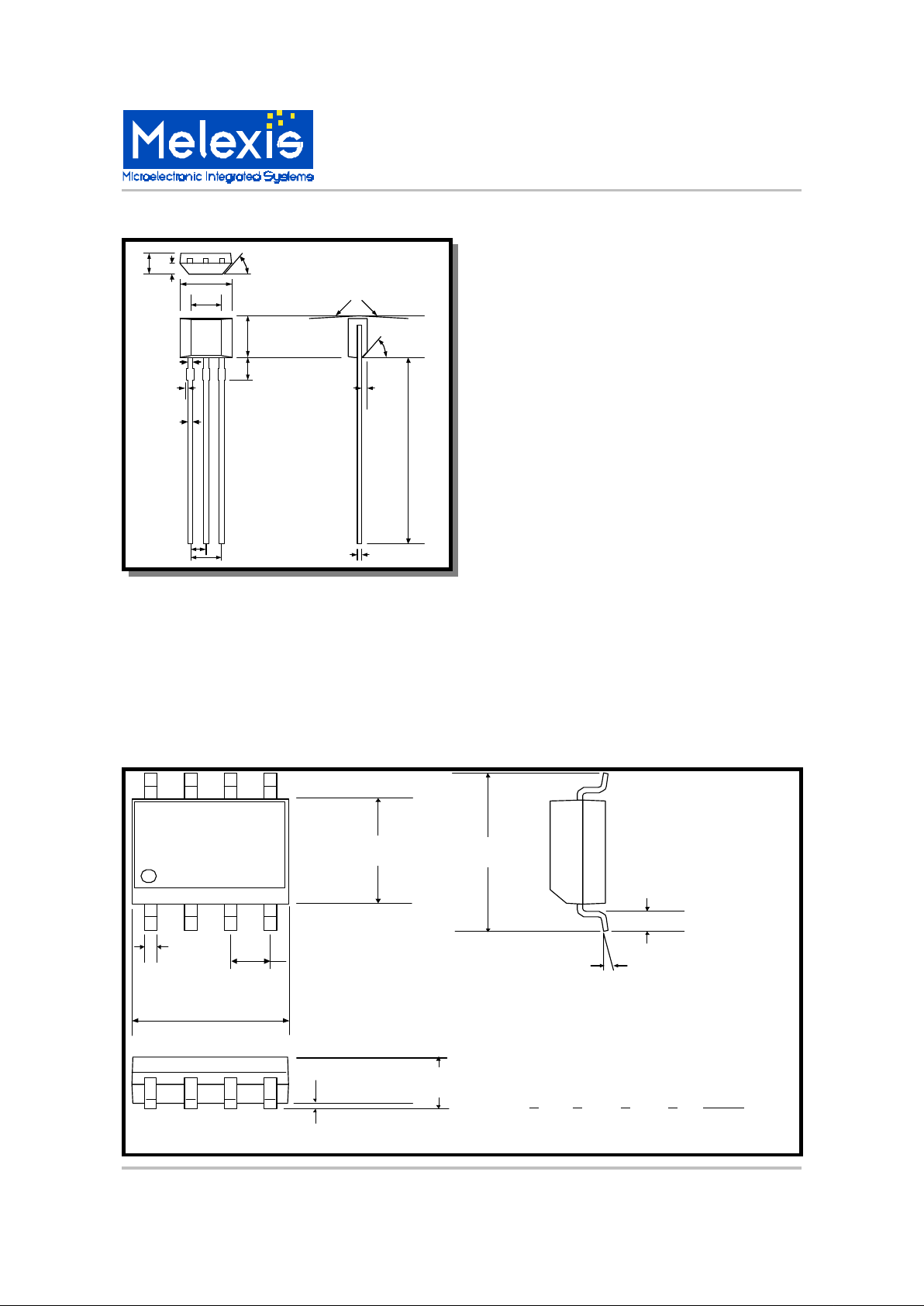
UA Package Dimensions
U79
905
1 2 3
*
1.60
1.40
45
o
Typical
4.30
3.90
2.64
2.34
0.84
0.63
3.20
2.80
1.75
1.55
0.48
0.43
0.20
0.00
0.41
0.35
1.30
1.24
2.57
2.51
5
o
Typical
45
o
Typical
0.38
Typical
(see note 3)
11.0
10.0
0.41
0.35
NOTES:
1.) Controlling dimension: mm
2.) Leads must be free of flash and
plating voids
3.) Leads must not arc toward
the rear of package
4.) Lead frame material:
EFTEC 64T
5.) Molding compound:
Sumitomo EME 6300H
6.) Package dimensions exclude
molding flash
7.) Tolerance is 0.254mm unless
otherwise specified
Notes:
1. Measurements in millimeters.
2. Body dimensions do not include mold flash,
protrusions, or burrs - not to exceed 0.15mm .
3. Lead frame material: copper 194.
4. Tolerances: +/- 0.25 mm unless otherwise
indicated.
5. Pin Connections:
1 2 3 4 5 to 8
n/c Out1 VSS Out2 n/c
4.80
4.95
0.33
0.51
1.27
3.81
3.99
0.38
1.27
0o to 8
o
5.79
6.20
1.47
1.73
0.010 min.
1 2 43
78 6 5
US79SO
0012
8-Pin Narrow SOIC
Package Dimensions
 Loading...