

Page 1
DATA SHEET
BIPOLAR ANALOG INTEGRATED CIRCUIT
µ
PC7900A Series
THREE TERMINAL NEGATIVE VOLTAGE REGULATOR
DESCRIPTION
µ
PC7900A series are monolithic three terminal negative regulators which employ internally current limiting, thermal
shut down, output transistor safe operating area protection make them essentially indestructible.
They are intended as fixed voltage regulators in a wide range of application including local on card regulation for
elimination of distribution problems associated wide single point regulation.
FEATURES
• Wide operation temperature range.
TA: –30 ˚C to +85 ˚C
• Good load regulation.
7 mV TYP. (250 mA ≤ I
• Low noise.
O ≤ 750 mA):
µ
PC7905AHF
ORDERING INFORMATION
Part Number Output Voltage Package
µ
PC7905AHF –5 V MP-45G (ISOLATED TO-220)
µ
PC7908AHF –8 V
µ
PC7912AHF –12 V
µ
PC7915AHF –15 V
µ
PC7918AHF –18 V
µ
PC7924AHF –24 V
MP-45G (ISOLATED TO-220)
MP-45G (ISOLATED TO-220)
MP-45G (ISOLATED TO-220)
MP-45G (ISOLATED TO-220)
MP-45G (ISOLATED TO-220)
The information in this document is subject to change without notice.
Document No. G10640EJ3V0DS00 (3rd edition)
(Previous No. IC-3486)
Date Published March 1997 N
Printed in Japan
©
1994
Page 2
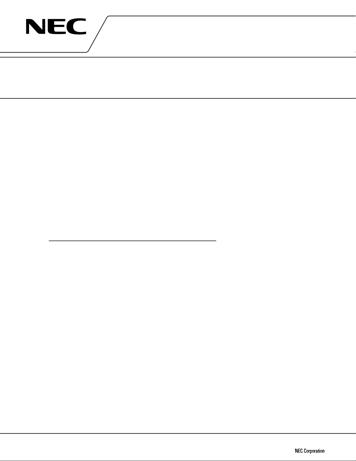
EQUIVALENT CIRCUIT
µ
PC7900A Series
R4 R15
Q12
R5
D1
D4
D5
R6
R7
Q14
R8
Q8
Q5
Q13
R1 R2
Q1
CONNECTION DIAGRAM
Q7
R10
Q2
R3
C1
R9 R21 R22
Q9
R16
Q4
Q3
R18
Q11
Q10
R20
R19
Marking
Q17
Q6
R23
Q27
Q22
Q29
Q20
R24
Q15
D6
R30
C4 R32
R31
Q21
Q18
C3
Q28
Q23
Q19
R27
Q16
R28
R29
Q24
D2
R13
Q25
R17
R14
R12
R25
R26
OUTPUT
Q26
R11
INPUT
TYPICAL CONNECTION
CIN : More than 2.2 µF
OUT : More than 0.33
C
D1 : Needed for VIN > VO
D2 : Needed for VO > GND
2
GND INPUT OUTPUT
D
1
INPUT
IN
C
µ
F
PC7900A
µ
D
2
OUT
C
OUTPUT
Page 3
µ
PC7900A Series
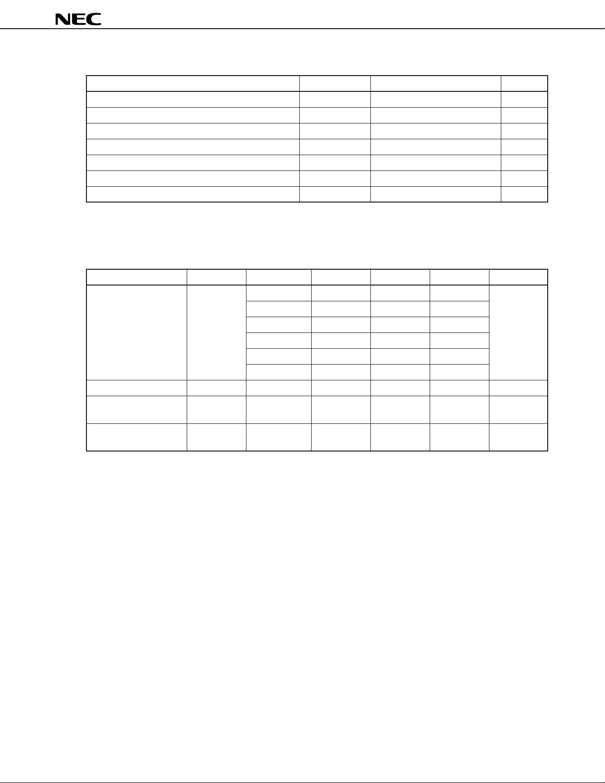
ABSOLUTE MAXIMUM REATINGS (TA = 25 ˚C)
Parameter Symbol Rating Unit
Input Voltage VIN –35/–40
Internal Power Dissipation PT 15
Operating Ambient Temperature Range TA –30 to +85 ˚C
Operating Junction Temperature Range TJ –30 to +150 ˚C
Storage Temperature Range Tstg –55 to +150 ˚C
Thermal Resistance (junction to case) Rth(J-C) 5.0 ˚C/W
Thermal Resistance (junction to ambient) Rth(J-A) 65 ˚C/W
Note 1
Note 2
Note 1.µPC7905A, 08A, 12A, 15A, 18A: –35 V, µPC7924A: –40 V
2. Internally limited
RECOMMENDED OPERATING CONDITIONS
Parameter Symbol Part Number MIN. TYP. MAX. Unit
µ
Input Voltage VIN
Output Current IO All 0.005 1 A
Operating Ambient TA All –30 +85 ˚C
Temperature
Operating Junction TJ All –30 +125 ˚C
Temperature Range
PC7905AHF –7 –10 –25 V
µ
PC7908AHF –10.5 –14 –25
µ
PC7912AHF –14.5 –19 –30
µ
PC7915AHF –17.5 –23 –30
µ
PC7918AHF –21 –27 –33
µ
PC7924AHF –27 –33 –38
V
W
3
Page 4
µ
PC7900A Series
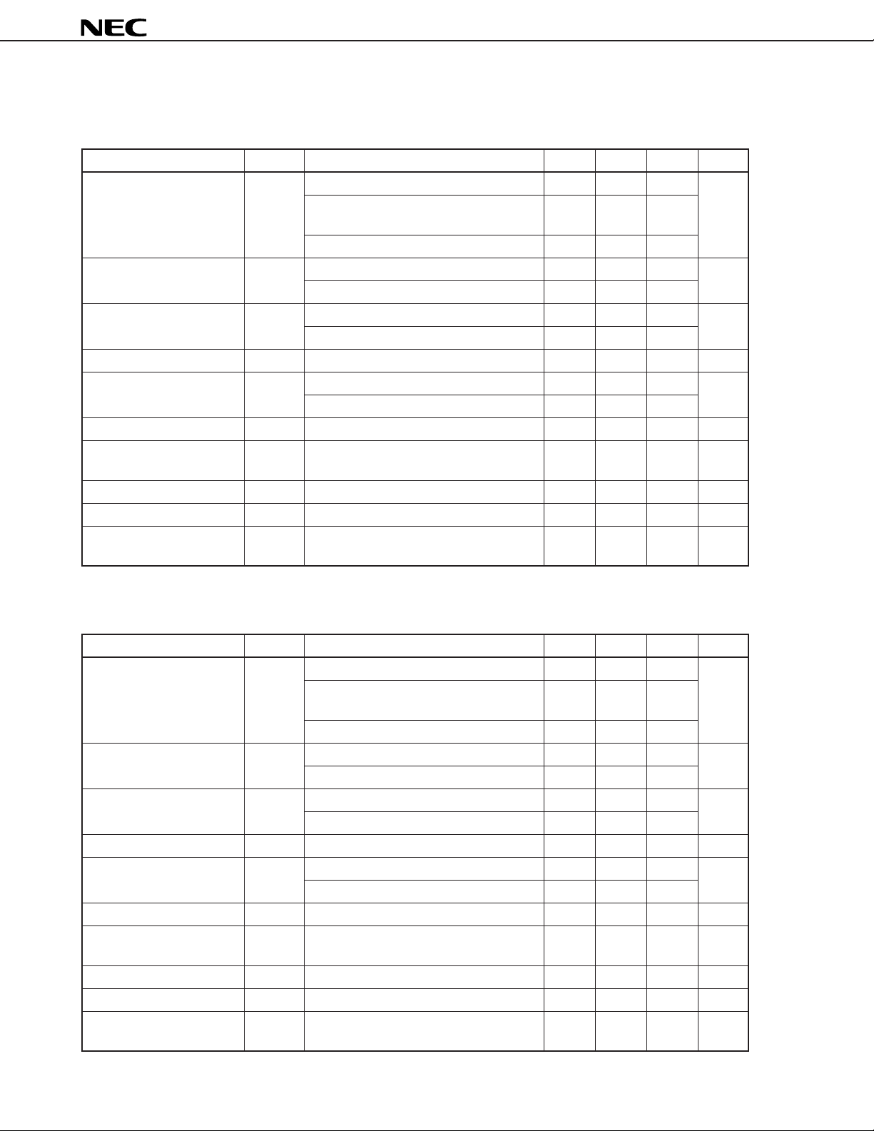
ELECTRICAL CHARACTERISTICS (TA = 25 ˚C)
µ
PC7905A
IN = –10 V, Io = 500 mA, 0 ˚C ≤ TJ ≤ +125 ˚C)
(V
Parameter Symbol Conditions MIN. TYP. MAX. Unit
Output Voltage VO TJ = 25 ˚C –4.8 –5.0 –5.2 V
–7 V ≤ VIN ≤ –20 V, 5 mA ≤ IO ≤ 1 A, –4.75 –5.25
PT ≤ 15 W
–30 ˚C ≤ TJ ≤ +125 ˚C –4.75 –5.25
Line Regulation REGIN TJ = 25 ˚C, –7 V ≤ VIN ≤ –25 V 25 100 mV
TJ = 25 ˚C, –8 V ≤ VIN ≤ –12 V 3 50
Load Regulation REGL TJ = 25 ˚C, 5 mA ≤ IO ≤ 1.5 A 30 100 mV
TJ = 25 ˚C, 250 mA ≤ IO ≤ 750 mA 7 50
Quiescent Current IBIAS TJ = 25 ˚C 3.6 6.0 mA
Quiescent Current Change ∆IBIAS –7 V ≤ VIN ≤ –25 V 1.3 mA
5 mA ≤ IO ≤ 1 A 0.5
Output Noize Voltage Vn TJ = 25 ˚C, 10 Hz ≤ f ≤ 100 kHz 77
Ripple Rejection R•R TJ = 25 ˚C, f = 120 Hz, –8 V ≤ VIN ≤ –18 V, 56 63 dB
IO = 500 mA
Dropout Voltage VDIF TJ = 25 ˚C, IO = 1A 1.2 V
Peak Output Current IOpeak TJ = 25 ˚C 1.6 2.2 2.8 A
Temperature Coefficient |∆VO/∆T| IO = 5 mA 0.36 mV/˚C
of Output Voltage
µ
Vr.m.s
µ
PC7908A
(VIN = –14 V, IO = 500 mA, 0 ˚C ≤ TJ ≤ +125 ˚C)
Parameter Symbol Conditions MIN. TYP. MAX. Unit
Output Voltage VO TJ = 25 ˚C –7.7 –8.0 –8.3 V
–10.5 V ≤ VIN ≤ –23 V, 5 mA ≤ IO ≤ 1 A, –7.6 –8.4
PT ≤ 15 W
–30 ˚C ≤ TJ ≤ +125 ˚C –7.6 –8.4
Line Regulation REGIN TJ = 25 ˚C, –10.5 V ≤ VIN ≤ –25 V 33 150 mV
TJ = 25 ˚C, –11 V ≤ VIN ≤ –17 V 14 75
Load Regulation REGL TJ = 25 ˚C, 5 mA ≤ IO ≤ 1.5 A 40 160 mV
TJ = 25 ˚C, 250 mA ≤ IO ≤ 750 mA 14 80
Quiescent Current IBIAS TJ = 25 ˚C 3.9 6.0 mA
Quiescent Current Change ∆IBIAS –10.5 V ≤ VIN ≤ –25 V 1.0 mA
5 mA ≤ IO ≤ 1 A 0.5
Output Noize Voltage Vn TJ = 25 ˚C, 10 Hz ≤ f ≤ 100 kHz 130
Ripple Rejection R•R TJ = 25 ˚C, –11.5 V ≤ VIN ≤ –21.5 V, 52 58 dB
f = 120 Hz, IO = 500 mA
Dropout Voltage VDIF TJ = 25 ˚C, IO = 1 A 1.2 V
Peak Output Current IOpeak TJ = 25 ˚C 1.6 2.2 2.8 A
Temperature Coefficient |∆VO/∆T| IO = 5 mA 0.32 mV/˚C
of Output Voltage
µ
Vr.m.s
4
Page 5

µ
PC7900A Series
µ
PC7912A
(VIN = –19 V, IO = 500 mA, 0 ˚C ≤ TJ ≤ +125 ˚C)
Parameter Symbol Conditions MIN. TYP. MAX. Unit
Output Voltage VO TJ = 25 ˚C –11.5 –12 –12.5 V
–14.5 V ≤ VIN ≤ –27 V, 5 mA ≤ IO ≤ 1 A, –11.4 –12.6
PT ≤ 15 W
–30 ˚C ≤ TJ ≤ +125 ˚C –11.4 –12.6
Line Regulation REGIN TJ = 25 ˚C, –14.5 V ≤ VIN ≤ –30 V 60 200 mV
TJ = 25 ˚C, –16 V ≤ VIN ≤ –22 V 25 100
Load Regulation REGL TJ = 25 ˚C, 5 mA ≤ IO ≤ 1.5 A 70 220 mV
TJ = 25 ˚C, 250 mA ≤ IO ≤ 750 mA 20 110
Quiescent Current IBIAS TJ = 25 ˚C 4.1 6.2 mA
Quiescent Current Change ∆IBIAS –14.5 V ≤ VIN ≤ –30 V 1.0 mA
5 mA ≤ IO ≤ 1A 0.5
Output Noize Voltage Vn TJ = 25 ˚C, 10 Hz ≤ f ≤ 100 kHz 140
Ripple Rejection R•R
Dropout Voltage VDIF TJ = 25 ˚C, IO = 1A 1.2 V
Peak Output Current IOpeak TJ = 25 ˚C 1.6 2.2 2.8 A
Temperature Coefficient |∆VO/∆T| IO = 5 mA 0.04 mV/˚C
of Output Voltage
TJ = 25 ˚C, f = 120 Hz, –15 V ≤ VIN ≤ –25 V,
IO = 500 mA
49 56 dB
µ
Vr.m.s
µ
PC7915A
(VIN = –23 V, IO = 500 mA, 0 ˚C ≤ TJ ≤ +125 ˚C)
Parameter Symbol Conditions MIN. TYP. MAX. Unit
Output Voltage VO TJ = 25 ˚C –14.4 –15 –15.6 V
–17.5 V ≤ VIN ≤ –30 V, 5 mA ≤ IO ≤ 1 A, –14.25 –15.75
PT ≤ 15 W
–30 ˚C ≤ TJ ≤ +125 ˚C –14.25 –15.75
Line Regulation REGIN TJ = 25 ˚C, –17.5 V ≤ VIN ≤ –30 V 60 200 mV
TJ = 25 ˚C, –20 V ≤ VIN ≤ –26 V 30 100
Load Regulation REGL TJ = 25 ˚C, 5 mA ≤ IO ≤ 1.5 A 100 300 mV
TJ = 25 ˚C, 250 mA ≤ IO ≤ 750 mA 30 150
Quiescent Current IBIAS TJ = 25 ˚C 4.2 6.2 mA
Quiescent Current Change ∆IBIAS –17.5 V ≤ VIN ≤ –30 V 1.0 mA
5 mA ≤ IO ≤ 1 A 0.5
Output Noize Voltage Vn TJ = 25 ˚C, 10 Hz ≤ f ≤ 100 kHz 240
Ripple Rejection R•R TJ = 25 ˚C, f = 120 Hz, 47 54 dB
–18.5 V ≤ VIN ≤ –28.5 V, IO = 500 mA
Dropout Voltage VDIF TJ = 25 ˚C, IO = 1 A 1.2 V
Peak Output Current IOpeak TJ = 25 ˚C 1.6 2.2 2.8 A
Temperature Coefficient |∆VO/∆T| IO = 5 mA 1.2 mV/˚C
of Output Voltage
µ
Vr.m.s
5
Page 6

µ
PC7900A Series
µ
PC7918A
(VIN = –27 V, IO = 500 mA, 0 ˚C ≤ TJ ≤ +125 ˚C)
Parameter Symbol Conditions MIN. TYP. MAX. Unit
Output Voltage VO TJ = 25 ˚C –17.3 –18 –18.7 V
–21 V ≤ VIN ≤ –33 V, 5 mA ≤ IO ≤ 1 A, –17.1 –18.9
PT ≤ 15 W
–30 ˚C ≤ TJ ≤ +125 ˚C –17.1 –18.9
Line Regulation REGIN TJ = 25 ˚C, –21 V ≤ VIN ≤ –33 V 60 240 mV
TJ = 25 ˚C, –24 V ≤ VIN ≤ –30 V 30 120
Load Regulation REGL TJ = 25 ˚C, 5 mA ≤ IO ≤ 1.5 A 125 360 mV
TJ = 25 ˚C, 250 mA ≤ IO ≤ 750 mA 47 180
Quiescent Current IBIAS TJ = 25 ˚C 4.1 6.5 mA
Quiescent Current Change ∆IBIAS –21 V ≤ VIN ≤ –33 V 1.0 mA
5 mA ≤ IO ≤ 1 A 0.5
Output Noize Voltage Vn TJ = 25 ˚C, 10 Hz ≤ f ≤ 100 kHz 190
Ripple Rejection R•R
Dropout Voltage VDIF TJ = 25 ˚C, IO = 1 A 1.2 V
Peak Output Current IOpeak TJ = 25 ˚C 1.6 2.2 2.8 A
Temperature Coefficient |∆VO/∆T| IO = 5 mA 0.24 mV/˚C
of Output Voltage
TJ = 25 ˚C, f = 120 Hz, –22 V ≤ VIN ≤ –32 V,
IO = 500 mA
45 53 dB
µ
Vr.m.s
µ
PC7924A
(VIN = –33 V, IO = 500 mA, 0 ˚C ≤ TJ ≤ +125 ˚C)
Parameter Symbol Conditions MIN. TYP. MAX. Unit
Output Voltage VO TJ = 25 ˚C –23.0 –24 –25.0 V
–27 V ≤ VIN ≤ –38 V, 5 mA ≤ IO ≤ 1 A, –22.8 –25.2
PT ≤ 15 W
–30 ˚C ≤ TJ ≤ +125 ˚C –22.8 –25.2
Line Regulation REGIN TJ = 25 ˚C, –27 V ≤ VIN ≤ –38 V 70 280 mV
TJ = 25 ˚C, –30 V ≤ VIN ≤ –36 V 37 140
Load Regulation REGL TJ = 25 ˚C, 5 mA ≤ IO ≤ 1.5 A 160 480 mV
TJ = 25 ˚C, 250 mA ≤ IO ≤ 750 mA 60 240
Quiescent Current IBIAS TJ = 25 ˚C 4.2 6.5 mA
Quiescent Current Change ∆IBIAS –27 V ≤ VIN ≤ –38 V 1.0 mA
5 mA ≤ IO ≤ 1 A 0.5
Output Noize Voltage Vn TJ = 25 ˚C, 10 Hz ≤ f ≤ 100 kHz 240
Ripple Rejection R•R
Dropout Voltage VDIF TJ = 25 ˚C, IO = 1 A 1.2 V
Peak Output Current IOpeak TJ = 25 ˚C 1.6 2.2 2.8 A
Temperature Coefficient |∆VO/∆T| IO = 5 mA 1.1 mV/˚C
of Output Voltage
TJ = 25 ˚C, f = 120 Hz, –28 V ≤ VIN ≤ –38 V,
IO = 500 mA
43 49 dB
µ
Vr.m.s
6
Page 7

TYPICAL CHARACTERISTICS (TA = 25 ˚C)
T
- T
A
P
20
15
10
5
- Total Power Dissipation - W
T
P
Without heatsink
TA - Operating Ambient Temperature - ˚C
3
With infinite heatsink
85 ˚C
1251007550250
Opeak
- (VIN - V
I
OUT
)
150
µ
PC7900A Series
O
- T
J
∆V
50
25
µ
0
–25
PC7905A
µ
PC7912A
µ
PC7918A
–50
–75
–100
–125
–150
- Output Voltage Deviation - mV
O
–175
∆V
–200
–25 0 25 50 75 100 125 150
IO = 5 mA
∆V
O
= VO(TJ = 25 ˚C) – VO(TJ)
TJ - Junction Temperature - ˚C
DIF
- I
O
V
2.0
2.5
2
1.5
- Peak Output Current - A
Opeak
I
1
020
4 8 12 16
(VIN - V
OUT
) - Input to Output
Differential Voltage - V
R·R - f
100
90
80
70
µ
PC7912A
µ
60
50
40
µ
PC7918A
30
20
R·R - Ripple Rejection - dB
10
0
1
10
10
2
10
3
f - Frequency - Hz
TJ = –30 ˚C
25 ˚C
125 ˚C
PC7905A
4
10
10
1.75
1.5
TJ = –30 ˚C
1.25
1.0
0.75
- Dropout Voltage - V
0.5
DIF
V
25 ˚C
125 ˚C
0.25
0.1 0.2 0.3 0.4 0.5 0.6 0.7 0.8 0.90
1
IO - Output Current - A
5
7
Page 8

µ
PC7900AHF Series
3PIN PLASTIC SIP (MP-45G)
µ
PC7900A Series
A
E
B
I
L
D
13
M
K
Y
H
J
Z
C
NOTE
FG
Each lead centerline is located within 0.25 mm (0.01 inch) of
its true position (T.P.) at maximum material condition.
M
N
P
Q
UV
ITEM MILLIMETERS INCHES
A 10.4 MAX. 0.410 MAX.
B 7.0 0.276
C 1.2 MIN. 0.047 MIN.
D 17.0±0.3 0.669
φ
E 0.130±0.008
F 0.75±0.10 0.030
G 0.25 0.010
H 2.54 (T.P.) 0.100 (T.P.)
I 5.0±0.3 0.197±0.012
J
K
L 8.5 0.335
M 8.5 0.335
N
P 2.8±0.2 0.110
Q 22.4 MAX. 0.882 MAX.
U 2.4±0.5 0.094
V
Y 8.9±0.7 0.350±0.028
Z 1.0 MIN. 0.039 MIN.
3.3±0.2
2.66 MAX.
4.8 MIN.
4.5±0.2 0.177±0.008
0.65±0.10 0.026
+0.013
–0.012
φ
+0.004
–0.005
0.105 MAX.
0.188 MIN.
+0.009
–0.008
+0.021
–0.020
+0.004
–0.005
P3HF-254B-2
8
Page 9

µ
PC7900A Series
RECOMMENDED SOLDERING CONDITIONS
When soldering this product, it is highly recommended to observe the conditions as shown below. If other
soldering processes are used, or if the soldering is performed under different conditions, please make sure to
consult with our sales offices.
For more details, refer to our document “SEMICONDUCTOR DEVICE MOUNTING TECHNOLOGY MANUAL”
(C10535E).
TYPES OF THROUGH HOLE MOUNT DEVICE
µ
PC7900AHF Series
Soldering Process Soldering Conditions Symbol
Wave soldering Solder temperature: 260 ˚C or below.
Flow Time: 10 seconds or below.
REFERENCE
Document Name Document No.
NEC semiconductor device reliability/quality control system. IEI-1212
Quality grade on NEC semiconductor devices. C11531E
Semiconductor device mounting technology manual. C10535E
IC package manual. C10943X
Guide to quality assurance for semiconductor devices. MEI-1202
Semiconductors selection guide. X10679E
9
Page 10

[MEMO]
µ
PC7900A Series
10
Page 11

[MEMO]
µ
PC7900A Series
11
Page 12

µ
PC7900A Series
[MEMO]
No part of this document may be copied or reproduced in any form or by any means without the prior written
consent of NEC Corporation. NEC Corporation assumes no responsibility for any errors which may appear in
this document.
NEC Corporation does not assume any liability for infringement of patents, copyrights or other intellectual property
rights of third parties by or arising from use of a device described herein or any other liability arising from use
of such device. No license, either express, implied or otherwise, is granted under any patents, copyrights or other
intellectual property rights of NEC Corporation or others.
While NEC Corporation has been making continuous effort to enhance the reliability of its semiconductor devices,
the possibility of defects cannot be eliminated entirely. To minimize risks of damage or injury to persons or
property arising from a defect in an NEC semiconductor device, customers must incorporate sufficient safety
measures in its design, such as redundancy, fire-containment, and anti-failure features.
NEC devices are classified into the following three quality grades:
"Standard", "Special", and "Specific". The Specific quality grade applies only to devices developed based on a
customer designated "quality assurance program" for a specific application. The recommended applications of
a device depend on its quality grade, as indicated below. Customers must check the quality grade of each device
before using it in a particular application.
Standard:Computers, office equipment, communications equipment, test and measurement equipment,
audio and visual equipment, home electronic appliances, machine tools, personal electronic
equipment and industrial robots
Special: Transportation equipment (automobiles, trains, ships, etc.), traffic control systems, anti-disaster
systems, anti-crime systems, safety equipment and medical equipment (not specifically designed
for life support)
Specific:Aircrafts, aerospace equipment, submersible repeaters, nuclear reactor control systems, life
support systems or medical equipment for life support, etc.
The quality grade of NEC devices is "Standard" unless otherwise specified in NEC's Data Sheets or Data Books.
If customers intend to use NEC devices for applications other than those specified for Standard quality grade,
they should contact an NEC sales representative in advance.
Anti-radioactive design is not implemented in this product.
M4 96.5
 Loading...