

Page 1
Double material sensor UDC-18GM50-255S-3E0
Technical data
General specifications
Sensing range 40 ... 100 mm optimal distance 75 mm
Transducer frequency 255 kHz
Indicators/operating means
LED green Indicator: single material detected
LED yellow Indicator: no material detected (air)
LED red Indicator: double material detected
Electrical specifications
Model Number
UDC-18GM50-255S-3E0
Features
• Ultrasonic system for reliable
detection of no, one, or two
overlapping sheet materials
• Short version
• No TEACH-IN required
• Function indicators visible from all
directions
• Insensitive to printing, colors, and
shining surfaces
• Very wide material spectrum,
finest papers up to thin sheet
metals as well as plastic- and
metal foils
• Perpendicular or inclined sensor
mounting relative to the sheet
plane possible
• Programmable
Diagrams
Operating voltage U
No-load supply current I
Time delay before availability t
Input
Input type Function input
Pulse length ≥ 100 ms
Impedance ≥ 4 kΩ
Output
Output type 3 switch outputs NPN, NO
Rated operating current I
Voltage drop U
Switch-on delay t
Switch-off delay t
Pulse extension min. 120 ms programmable
Ambient conditions
Ambient temperature 0 ... 60 °C (32 ... 140 °F)
Storage temperature -40 ... 85 °C (-40 ... 185 °F)
Mechanical specifications
Connection type cable PVC , 2 m
Core cross-section 0.14 mm
Degree of protection IP67
Material
Housing nickel plated brass; plastic components: PBT
Transducer epoxy resin/hollow glass sphere mixture; polyurethane foam
Mass 150 g
Factory settings
Program 1
General information
Supplementary information Switch settings of the external programming adapter:
Compliance with standards and
directives
Standard conformity
Standards EN 60947-5-2:2007+A1:2012
Approvals and certificates
UL approval cULus Listed, General Purpose, Class 2 Power Source
CSA approval cCSAus Listed, General Purpose, Class 2 Power Source
CCC approval CCC approval / marking not required for products rated ≤36 V
B
0
v
e
d
on
off
18 ... 30 V DC , ripple 10 %
< 65 mA
< 500 ms
0-level: -U
1-level: +U
3 x 100 mA , short-circuit/overload protected
≤ 3 V
approx. 35 ms
approx. 35 ms
"output load": pull-up
"output logic": inv
IEC 60947-5-2:2007 + A1:2012
... -UB + 1V
B
- 1 V ... +U
B
2
SS
B
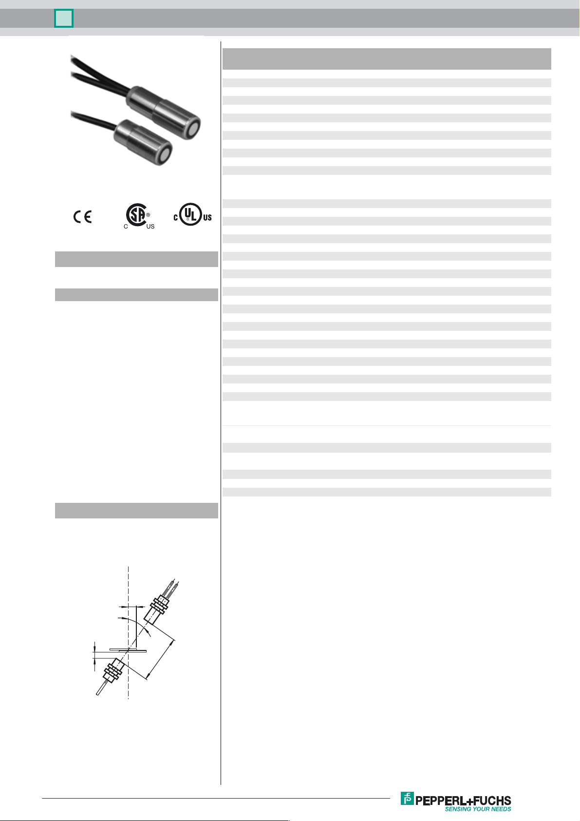
Mounting/Adjustment
Recommended distances
a = 15 ... 25 mm
b ≥ 10 mm
d = 60 ... 80 mm
β = 20° ... 40°
a
Release date: 2017-09-25 08:46 Date of issue: 2017-09-25 206053_eng.xml
Refer to “General Notes Relating to Pepperl+Fuchs Product Information”.
b
β
d
1
Page 2
Double material sensor UDC-18GM50-255S-3E0
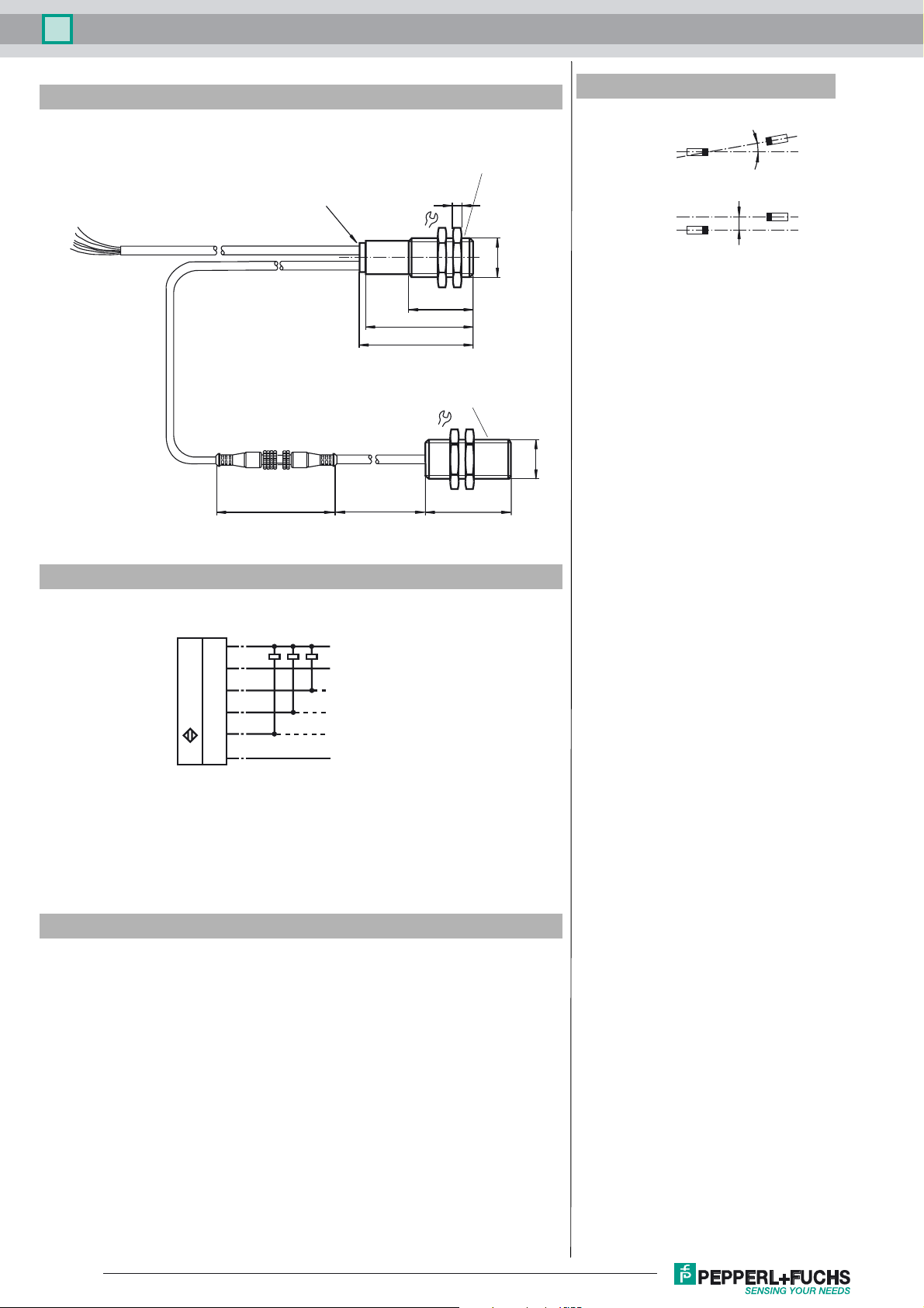
Dimensions
wires 70 mm with
wire end ferrules
l = 2 m
l = 0.5 m
ø 15
70
LEDs
500
Additional Information
Angular misalignment
< +/- 1°
Evaluation unit with
receiver unit
4
24
M18 x 1
30
50
53
Emitter unit
24
M18 x 1
40
α
Sensor offset
s < +/- 1 mm
α
s
Electrical Connection
Standard symbol/Connection:
Double sheet control
(BN)
(PK)
(WH)
(BK)
U
(GY)
(BU)
Accessories
UC-PROG1-USB
Programming adapter
UDB-Cable-2M
MH-UDB01
Mounting bracket for double sheet monitor
UDB-Cable-1M
+U
B
Function input
Output single sheet
Output double sheet
Output air
-U
B
V15S-G-0,3M-PUR-WAGO
Male cordset, M12, 5-pin, PUR cable with WAGO terminals
Ultraschall-Sensoren DTM
DTM devices for communication with cube style and UMC... sensors
PACTware 4.1
FDT Framework
Refer to “General Notes Relating to Pepperl+Fuchs Product Information”.
2
Release date: 2017-09-25 08:46 Date of issue: 2017-09-25 206053_eng.xml
Page 3

Double material sensor UDC-18GM50-255S-3E0
Description of the sensor functions
Ultrasonic double material sensors are used in any situation where it is necessary to make an automatic distinction between a single
sheet of material and a double sheet of material in order to provide protection for a machine and/or to avoid wastage. The double
material sensor is based on the ultrasonic single-pass principle. The following situations can be detected:
- No material, i.e. air
- Single layer of material
- 2 or more layers of material
The evaluation of the signals is carried out with a microprocessor system. As a consequence of the evaluation the corresponding switch
outputs are set. Changing ambient conditions, such as temperature and humidity, are automatically compensated. The evaluation electronics system is built into an evaluation unit, together with a sensor head, and contained in a compact M18 metal housing.
Interface
The sensor has 6 connections. The function of the connections is shown in the following table. The function input (PK) is used to configure the sensor parameters. (see Output pulse expansion, alignment aids and program select). During operation, the function input
must always be permanently connected to +U
Color Interface Note
BN +U
WH Switch output, single material Pulse width corresponding to the event
BK Switch output, double material Pulse width corresponding to the event
GY Switching output air Pulse width that corresponds to the event
PK -U
BU -U
B
B
B
/+U
B
or -UB to prevent possible faults or malfunctions.
B
Function input for parameterization/pulse
extension.
Normal operation
The sensor operates in normal mode if the function input (PK) is set to -UB or +UB when the supply voltage is applied (power on) as
specified in the output pulse expansion table (see below).
Display:
Yellow LED: Air detection
Green LED: Detection of single material
Red LED: Detection of double material
Switching outputs:
The switching outputs are only active in normal mode!
White: WH Single material output
Black: BK Double material output
Gray: GY Air output
Output pulse expansion
A minimum pulse width of 120 ms can be selected for all the output pulses of the three switching outputs by connecting the function
input (PK) to +U
Interface (PK) Switching behavior (after power on)
-U
+U
.
B
B
B
No output pulse expansion of switching outputs
Output pulse expansion of all switching outputs to a minimum of 120
ms
Caution!
This can lead to a situation where more than one switch output is switched through!
Programs
The sensor has 4 programs for different application areas. This enables a wide range of materials to be detected. The user can select
the program most suited to the relevant application.
The default setting program 1 is selected so that the settings of the majority of applications do not need modifying.
Program numbers Notes*
1 Standard setting. Covers a wide range of materials
2 Thick, heavy materials
3 Thin materials
4 The thinnest of materials, films
The applications specified in Programs 1 ... 4 provide orientation values for the user. In a specific individual case the selection of the
suitable program for the respective material in use has to be obtained empirically. In this procedure the starting point should be the
standard Program 1.
Adjustment options using the function input
The adjustment options are indicated in the following, together with the function input.
Release date: 2017-09-25 08:46 Date of issue: 2017-09-25 206053_eng.xml
Refer to “General Notes Relating to Pepperl+Fuchs Product Information”.
3
Page 4

Double material sensor UDC-18GM50-255S-3E0
... and set function input (PK)
to +U
or -U
B
Power ON
... and function input
(PK) unconnected
Programming
-U
Amplitude control
(yellow LED)
display
B
B
-U
B
Normal operation
Programming
display
Program select
(green LED)
-U
+U
B
B
Function input
(PK) unconnected
Activate/Deactivate
output pulse
expansion
+U
Programming mode
B
No function Toggle cyclically
+U
B
next program
Program display
The preset sensor program can be displayed by disconnecting the function input (PK) from the power supply during normal operation.
The green LED indicates the program number (number of flashing pulses (1...4) = program number).
The outputs are inactive during this time.
If the function input (PK) is disconnected from the power during operation due to a fault (cable break, loosening due to vibration), the
program display also serves as a fault display. Changing to programming mode is not possible.
Programming mode
To activate the programming mode,
the function input (PK) must be disconnected from the power when the supply voltage is applied (power on). The flashing green LED
linked to the sensor indicates the preset program first (number of flashing pulses (1...4) = program number).
By briefly setting the function input (PK) to -Ub (>500ms), it is now possible to switch cyclically between the amplitude control and the
program selection.
By disconnecting the supply voltage, you exit the programming mode and the current selected program setting is applied.
The switching outputs are deactivated while the sensor is parameterized!
Amplitude control
During installation, the amplitude control can be used to check whether the ultrasonic amplitude at the receiver is sufficient.
If the transmitter is not aligned properly in relation to the receiver, maximum sound energy is not transmitted to the receiver, which
may result in the incorrect detection of materials.
When the sensor detects an area of air (yellow LED lights up), the UDC begins to display the strength of the measured amplitude signal:
- if the signal is weak, the yellow LED flashes at low frequency
- the flashing frequency increases in line with the signal strength
- the yellow LED lights up continuously when the signal strength is sufficient.
The single sheet fu nction (green LED) and double sheet function (red LED) are now active. This can be used to check the correct func-
tion of the double material sensor.
Program select
In program select mode, briefly setting the (PK) to +Ub (>500ms) selects the next program cyclically (number of flashing pulses from
the green LED = program number). A flashing sequence that has already started is not interrupted by a program change.
Note:
A complete device consists of one ultrasonic sensor and one evaluation unit with the ultrasonic receiver. The sensor heads are optimally matched to each other in the ex-works condition and should therefore not be used separately. The connector disconnection point
on the transmitter/receiver connection cable is merely provided to simplify assembly.
Because of their physical condition, materials that are perforated or otherwise contain holes are not always suitable for double sheet
material detection.
If a number of UDC double material sensors are installed close together there is the possibility of mutual interference, leading to the
occurrence of faults. Mutual interference can be avoided by suitable countermeasures implemented when planning the system.
On installation, care should be taken, that the ultrasonic signal cannot pass around the material to be detected due to multiple reflecti
ons. This can happen if, for example, there are large surfaces capable of reflecting the sound at right angles to the direction of propagation of the sound. This can be the case when unsuitable clamping devices are used, or may be due to plant components with large
surfaces. In the case of reflecting plant components, these must either be clad with sound-absorbing material, or an alternative mounting location found for the sensor.
Release date: 2017-09-25 08:46 Date of issue: 2017-09-25 206053_eng.xml
Refer to “General Notes Relating to Pepperl+Fuchs Product Information”.
4
Page 5

Double material sensor UDC-18GM50-255S-3E0
Correct functionality of the sensor can only be ensured if the emitter and receiver are adjusted so they are exactly centred on each other.
The sensor heads and the evaluation unit must not be grounded.
To avoid an unintended grounding, please use the plastic nuts for fixation, which are in scope of delivery. These
nuts are equipped with a centering ring at one side, which ensures, that there is no electrical contact to the environmental material. The drawing beside shows the 2 possible nut orientations. The drilling hole diameter in
the carrier has to be 20 mm.
Parameterization using PAC Tw a r e DTM
The double sheet sensor can be connected using a V15S-G-0.3M-PUR-WAGO terminal adapter.
M12 socket for
the UC-PROG1
V15S-G-0.3M-PUR-WAGO
Connection cable for
the double sheet sensor
Connect the sensor to the terminal adapter according to the table below.
Terminal adapter wire color Sensor cable wire color
Brown Brown
Blue Blue
Black Black
Gray Pink
The sensor features a time lock. If no communication request occurs, the time lock blocks parameterization of the sensor 30 seconds
after the supply voltage is connected. Start PACTware before switching on the sensor so that the communication request can be made
in time.
Release date: 2017-09-25 08:46 Date of issue: 2017-09-25 206053_eng.xml
Refer to “General Notes Relating to Pepperl+Fuchs Product Information”.
5
 Loading...