

Page 1
Ultrasonic sensor UB2000-30GM-E4-V15
Technical data
General specifications
Sensing range 80 ... 2000 mm
Adjustment range 120 ... 2000 mm
Dead band 0 ... 80 mm
Standard target plate 100 mm x 100 mm
Transducer frequency approx. 180 kHz
Response delay approx. 150 ms
Indicators/operating means
Model Number
UB2000-30GM-E4-V15
Single head system
Features
• Switch output
• 5 different output functions can be
set
•Program input
• Synchronization options
• Deactivation option
• Temperature compensation
• Insensitive to compressed air
Diagrams
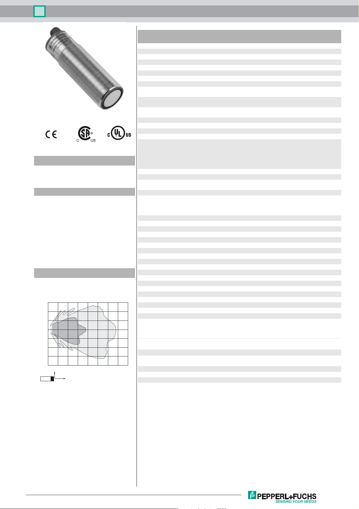
Characteristic response curve
Distance Y [m]
0.6
0.4
0.2
0.0
-0.2
-0.4
-0.6
-0.8
0.0 0.5 1.0 1.5 2.0 2.5 3.0 3.5 4.0
Curve 1: flat surface 100 mm x 100 mm
Curve 2: round bar, Ø 25 mm
2
Y
X
1
Distance X [m]
LED green solid: Power-on
LED yellow solid: switching state switch output
LED red normal operation: "fault"
Electrical specifications
Operating voltage U
No-load supply current I
Input/Output
B
0
Synchronization bi-directional
Synchronization frequency
Common mode operation ≤ 30 Hz
Multiplex operation ≤ 30 Hz / n , n = number of sensors , n ≤ 5
Input
Input type 1 program input,
Output
Output type 1 switch output NPN , Normally open/closed , programmable
Rated operating current I
Voltage drop U
Repeat accuracy ≤ 0.5 % of switching point
d
e
Switching frequency f ≤ 3.3 Hz
Range hysteresis H 1 % of the set operating distance
Temperature influence < 2 % of far switch point
Ambient conditions
Ambient temperature -25 ... 70 °C (-13 ... 158 °F)
Storage temperature -40 ... 85 °C (-40 ... 185 °F)
Mechanical specifications
Connection type Connector M12 x 1 , 5-pin
Degree of protection IP65
Material
Housing nickel plated brass; plastic components: PBT
Transducer epoxy resin/hollow glass sphere mixture; polyurethane foam
Mass 140 g
Factory settings
Output Switch point A1: 220 mm
Compliance with standards and
directives
Standard conformity
Standards EN 60947-5-2:2007+A1:2012
Approvals and certificates
UL approval cULus Listed, General Purpose
CSA approval cCSAus Listed, General Purpose
CCC approval CCC approval / marking not required for products rated ≤36 V
flashing: program function object detected
flashing: program function
program function: no object detected
10 ... 30 V DC , ripple 10 %
≤ 50 mA
0 level -U
1 level: +4 V...+U
input impedance: > 12 KOhm
synchronization pulse: ≥ 100 µs, synchronization interpulse
period: ≥ 2 ms
operating range 1: -U
+U
input impedance: > 4.7 kΩ; program pulse: ≥ 1 s
...+1 V
B
B
SS
B
... +1 V, operating range 2: +4 V ...
B
200 mA , short-circuit/overload protected
≤ 2.5 V
Switch point A2: 2100 mm
output function: Window mode
output behavior: NO contact
IEC 60947-5-2:2007 + A1:2012
Release date: 2017-07-03 12:07 Date of issue: 2017-07-03 097968_eng.xml
Refer to “General Notes Relating to Pepperl+Fuchs Product Information”.
1
Page 2
Ultrasonic sensor UB2000-30GM-E4-V15
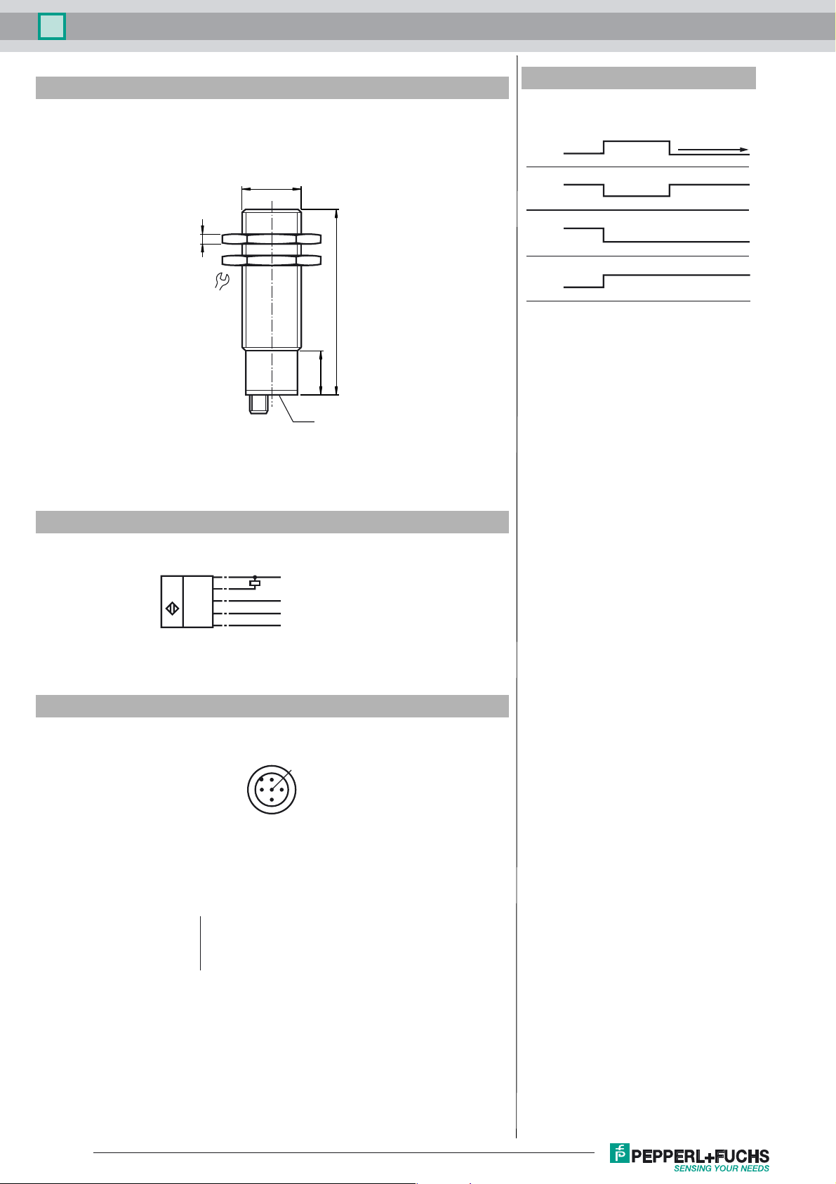
Dimensions
Additional Information
Programmable output modes
1. Window mode, normally open mode
A1 < A2:
A1
M30 x 1.5
2. Window mode, normally closed mode
A2 < A1:
A2
3. One switch point, normally open mode
5
A1 -> ∞:
A2
4. One switch point, normally closed mode
36
94
A2 -> ∞:
A1
5. A1 -> ∞, A2 -> ∞: Object presence detection mode
Object detected: Switch output closed
No object detected: Switch output open
22
LED
object distance
A2
A1
Electrical Connection
Standard symbol/Connections:
(version E4, npn)
U
Wire colors in accordance with EN 60947-5-2.
Pinout
Wire colors in accordance with EN 60947-5-2
1 BN
2 WH
3 BU
4 BK
5 GY
(BN)
1
(BK)
4
2
(WH)
5
(GY)
3
(BU)
2
+ U
B
Switch output
Program input
Sync. input
- U
B
1
5
4
3
(brown)
(white)
(blue)
(black)
(gray)
Release date: 2017-07-03 12:07 Date of issue: 2017-07-03 097968_eng.xml
Refer to “General Notes Relating to Pepperl+Fuchs Product Information”.
2
Page 3

Ultrasonic sensor UB2000-30GM-E4-V15
Accessories
BF 30
Mounting flange, 30 mm
BF 30-F
Mounting flange with dead stop, 30 mm
BF 5-30
Universal mounting bracket for cylindrical sensors with a diameter of 5 ... 30 mm
UVW90-M30
Ultrasonic -deflector
UVW90-K30
Ultrasonic -deflector
UB-PROG2
Programming unit
V15-G-2M-PVC
Female cordset, M12, 5-pin, PVC cable
Description of Sensor Functions
Programming procedure
The sensor features a programmable switch output with two programmable switch points. Programming the switch points and the operating mode
is done by applying the supply voltage -U
s. LEDs indicate whether the sensor has recognized the target during the programming procedure.
Note:
If a programming adapter UB-PROG2 is used for the programming procedure, button A1 is assigned to -UB and button A2 is assigned to +UB.
Programming of the switch output
Window Modes
Normally open (NO) output
1. Place the target at the near end of the desired switch window
2. Program the window boundary by applying -U
3. Disconnect the Teach-In input from -U
4. Place the target at the far end of the desired switch window
5. Program the window boundary by applying +U
6. Disconnect the Teach-In input from +U
Normally closed (NC) output
1. Place the target at the near end of the desired switch window
2. Program the window boundary by applying +U
3. Disconnect the Teach-In input from +U
4. Place the target at the far end of the desired switch window
5. Program the window boundary by applying -U
6. Disconnect the Teach-In input from -U
Switch Point Modes
Normally open (NO) output
1. Place the target at the desired switch point position
2. Program the switch point by applying +U
3. Disconnect the Teach-In input from +U
4. Cover the sensor face with hand or remove all objects from sensing range
5. Program the switch point by applying -U
6. Disconnect the Teach-In input from -U
Normally closed (NC) output
1. Place the target at the desired switch point position
2. Program the switch point by applying -U
3. Disconnect the Teach-In input from -U
4. Cover the sensor face with hand or remove all objects from sensing range
5. Program the switch point by applying +U
6. Disconnect the Teach-In input from +U
Object Detection Mode
1. Cover the sensor face with hand or remove all objects from sensing range
2. Apply -U
to the Teach-In input (red and yellow LEDs flash)
B
3. Disconnect the Teach-In input from +U
4. Apply +U
5. Disconnect the Teach-In input from +U
to the Teach-In input (red and yellow LEDs flash)
B
or +UB to the Teach-In input. The supply voltage must be applied to the Teach-In input for at least 1
B
to the Teach-In input (yellow and green LEDs flash)
B
to save the window boundary
B
to the Teach-In input (yellow and green LEDs flash)
B
to save the window boundary
B
to the Teach-In input (yellow and green LEDs flash)
B
to save the window boundary
B
to the Teach-In input (yellow and green LEDs flash)
B
to save the window boundary
B
to the Teach-In input (yellow and green LEDs flash)
B
to save the switch point
B
to the Teach-In input (red and yellow LEDs flash)
B
to save the switch point
B
to the Teach-In input (yellow and green LEDs flash)
B
to save the switch point
B
to the Teach-In input (red and yellow LEDs flash)
B
to save the switch point
B
to save the setting
B
to save the setting
B
Factory settings
See technical data.
Display
The sensor provides LEDs to indicate various conditions.
Release date: 2017-07-03 12:07 Date of issue: 2017-07-03 097968_eng.xml
Refer to “General Notes Relating to Pepperl+Fuchs Product Information”.
3
Page 4

Ultrasonic sensor UB2000-30GM-E4-V15
#
During Normal operation
Proper operation
Interference (e.g. compressed air)
During sensor programming
Object detected
No object detected
Object uncertain (programming invalid)
Green LED Red LED Yellow LED
On
Off
Flashing
Off
Off
Off
Flashing
Off
Flashing
Flashing
Switching state
Previous state
Flashing
Flashing
Flashing
Synchronization
This sensor features a synchronization input for suppressing ultrasonic mutual interference ("cross talk"). If this input is not connected, the sensor
will operate using internally generated clock pulses. It can be synchronized by applying an external square wave. The pulse duration must be ≥
100 µs. Each falling edge of the synchronization pulse triggers transmission of a single ultrasonic pulse. If the synchronization signal remains low
for ≥ 1 second, the sensor will revert to normal operating mode. Normal operating mode can also be activated by opening the signal connection
to the synchronization input (see note below).
If the synchronization input goes to a high level for > 1 second, the sensor will switch to standby mode, indicated by the green LED. In this mode,
the outputs will remain in the last valid output state.
Note:
If the option for synchronization is not used, the synchronization input has to be connected to ground (0 V) or the sensor must be operated via a
V1 cordset (4-pin).
The synchronization function cannot be activated during programming mode and vice versa.
The following synchronization modes are possible:
1. Several sensors (max. number see technical data) can be synchronized together by interconnecting their respective synchronization inputs.
In this case, each sensor alternately transmits ultrasonic pulses in a self multiplexing mode. No two sensors will transmit pulses at the same
time (see note below).
2. Multiple sensors can be controlled by the same external synchronization signal. In this mode the sensors are triggered in parallel and are synchronized by a common external synchronization pulse.
3. A separate synchronization pulse can be sent to each individual sensor. In this mode the sensors operate in external multiplex mode (see note
below).
4. A high level (+U
Note:
Sensor response times will increase proportionally to the number of sensors that are in the synchronization string. This is a result of the multiplexing of the ultrasonic transmit and receive signal and the resulting increase in the measurement cycle time.
) on the synchronization input switches the sensor to standby mode.
B
Installation conditions
If the sensor is installed in an environment where the temperature can fall below 0 °C, one of these mounting flanges must be used for mounting:
BF30, BF30-F, or BF 5-30.
If it is intended to operate the sensor at - 25 °C, we recommend discussing the mounting situation with a Pepperl + Fuchs application specialist
to ensure a trouble-free operation.
If the sensor is mounted in a through hole using the included steel nuts, it must be mounted at the middle of the threaded housing. If it must be
mounted at the front end of the threaded housing, plastic nuts with centering ring (optional accessories) must be used.
Release date: 2017-07-03 12:07 Date of issue: 2017-07-03 097968_eng.xml
Refer to “General Notes Relating to Pepperl+Fuchs Product Information”.
4
 Loading...