

Page 1
Ultrasonic sensor
UB2000-30GM-E0-V15
Features
• Switch output
• 5 different output functions can be set
• TEACH-IN input
• Synchronisation options
• Deactivation option
Electrical connection
Standard symbol/Connections:
(version E0, npn)
U
1
4
2
5
3
+ U
B
Switch output
Teaching input
Sync. input
- U
B
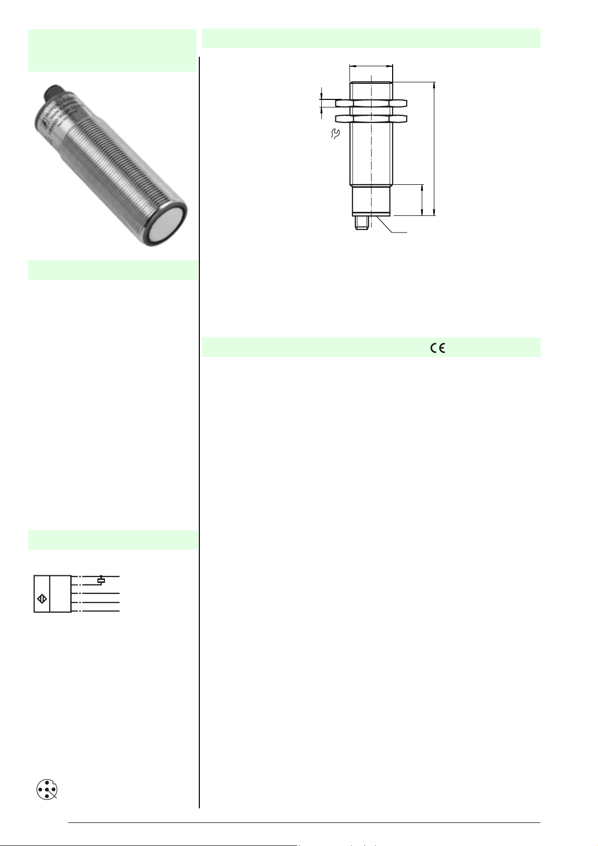
Dimensions
M30x1.5
5
36
94
22
LED
Technische DatenTechnical data
General specifications
Sensing range 200 ... 2000 mm
Unusable area 0 ... 200 mm
Standard target plate 100 mm x 100 mm
Transducer frequency approx. 175 kHz
Response delay approx. 145 ms
Indicators/operating means
LED green "Power on", TEACH-IN function object detected
LED yellow indication of the switching state, TEACH-IN function-no object detected
LED red "Error", object uncertain
Electrical specifications
Operating voltage 20 ... 30 V DC , ripple 10 %
No-load supply current I
Input
Input type 1 TEACH-IN input,
Pulse length Synchronisation pulse: ≥ 100 µs
Synchronisation frequency
Common mode operation ≤ 40 Hz
Multiplex operation ≤ 40/n Hz , n = number of sensors
Output
Output type 1 switch output E0/E1, npn, normally open/closed, programmable
Repeat accuracy ≤ 1 %
Rated operational current I
Voltage drop U
Switching frequency f max. 3.4 Hz
Range hysteresis H ≤ 1 % of the set operating distance
Temperature influence 0.17 % / K
Standard conformity
Standards EN 60947-5-2
Ambient conditions
Ambient temperature -25 ... 70 °C (248 ... 343 K)
Storage temperature -40 ... 85 °C (233 ... 358 K)
Mechanical specifications
Protection degree IP65
Connection connector V15 (M12 x 1), 5 pin
Material
Housing brass, nickel-plated, plastic components PBT
Transducer epoxy resin/hollow glass sphere mixture; polyurethane foam
Mass 145 g
d
≤ 60 mA
0
operating distance 1: -U
synchronous input
level 0: -U
Input impedance 27 kOhm
Synchronisation pulse pause: ≥ 100 µs
200 mA , short-circuit/overload protected
e
≤ 3 V
... (-UB + 1 V), level 1: (-UB + 5 V) ... +UB
B
SS
... (-UB +2 V), operating distance 2: (+UB -2 V) ... +UB 1
B
Connector V15
2
1
3
5
4
Subject to reasonable modifications due to technical advances. Copyright Pepperl+Fuchs, Printed in Germany
1
Pepperl+Fuchs Group • • • •
2005-07-27 039557_ENG.xml
Page 2
HinweiseNotes BestellbezeichnungModel number
UB2000-30GM-E0-V15
Function
Synchronization
The sensor features a synchronization input for the suppression of mutual interference. It can be synchronized by applying a square wave voltage. The falling edge
of a synchro
nization pulse at the synchronization input starts a measuring cycle. A
low level > 1 s or an open synchronization input will result in the non-synchronized
normal operation of the sensor. A high level at the synchronization input disables
the sensor. Synchronization cannot be performed during TEACH-IN and vice versa.
Two operating modes are possible:
1. The sync. inputs of 2 ... 5 Sensors are connected with each other. The sensors synchronize them-
selves and operate cyclically (multiplex mode).
2. Multiple sensors can be controlled by the same synchronization signal. The sensors are synchro-
nized.
3. The synchronization pulses are sent cyclically to individual sensors. The sensors operate in mul-
tiplex mode.
n
In case of synchronized operation, the respo
se time of the sensor increases due
to a longer measuring cycle time caused by synchronization.
Note:
If the option for synchronization is not used, the synchronization input has to be connected to ground (0V) or the sensor has to
be operated via a V1 cable connector
(4-pin).
Setting the switching points
The ultrasonic sensor features a switch output with
two teachable switching points.
These are set by applying the supply voltage -UB or +UB to the TEACH-IN input.
The supply voltage must be applied to the TEACH-IN input for at least 1 s. LEDs
indicate whether the sensor has recognised the target during the TEACH-IN procedure. Switching point A1 is taught with -UB, A2 with +UB.
Five different output functions can be set:
Function TEACH-IN procedure
Window mode,
close function
- Set object to near switching point
- Teach switching point A1 with -UB
- Set object to far switching point
- Teach switching point A2 with +UB
Window mode,
open function
- Set object to near switching point
- Teach switching point A2 with +UB
- Set object to far switching point
- Teach switching point A1 with -UB
1 switching point,
close function
- Set object to near switching point
- Teach switching point A2 with +UB
- Cover sensor or remove all objects from sensing range
- Teach switching point A1 with -UB
1 switching point,
open function
- Set object to near switching point
- Teach switching point A1 with -UB
- Cover sensor or remove all objects from sensing range
- Teach switching point A2 with +UB
Detection of
ject p
ob
resence
- Cover sensor or remove all objects from sensing range
- Teach switching point A1 with -UB
- Teach switching point A2 with +UB
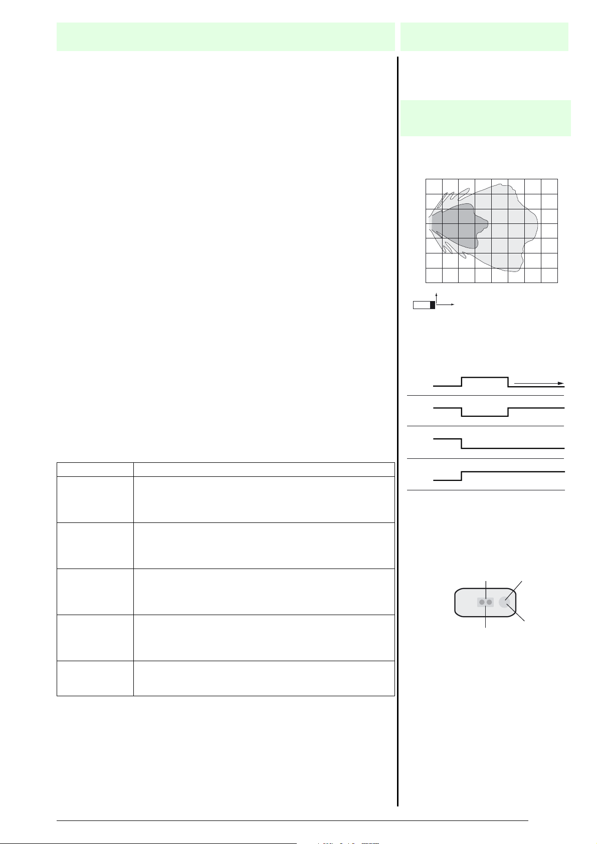
Characteristic curves/additional
information
Characteristic response curve
Distance Y [m]
0.6
0.4
0.2
0.0
-0.2
-0.4
-0.6
-0.8
0.0 0.5 1.0 1.5 2.0 2.5 3.0 3.5 4.0
Y
X
Curve 1: flat surface 100 mm x 100 mm
Curve 2: round bar, Ø 25 mm
Programmed switching output function
1. Window mode, normally open function
A1 < A2:
A1
2. Window mode, normally closed function
A2 < A1:
A2
3. One switch point, normally open function
A1 -> ∞:
A2
4. One switch point, normally closed function
A2 -> ∞:
A1
5. A1 -> ∞, A2 -> ∞: Detection of object presence
Object detected: Switch output closed
No object detected: Switch output open
LED-Window
"Power on"/Disturbance
2
Dual-LED
green/red
object range
A2
A1
1
Distance X [m]
LED
yellow
Switch output
Subject to reasonable modifications due to technical advances. Copyright Pepperl+Fuchs, Printed in Germany
Pepperl+Fuchs Group • • • •
2
Page 3

Ultrasonic sensor
Default setting of switching points: A1 = blind range, A2 = nominal distance
Displays in dependence on operating mode
Teach switching point
Object detected
No object detected
Object uncertain (TEACH-IN invalid)
Normal operation On Off Switching state
Interference (e.g. compressed air) Off Flashing Previous state
Mounting conditions
If the sensor is installed in places where th
clamp must be used.
Green LED Red LED Ye l lo w L ED
Flashing
Flashing
Off
e operating temperature can fall below 0 °C, the BF30, BF30-F or BF 5-30 fixing
UB2000-30GM-E0-V15
Off
Off
Flashing
Off
On
Off
Subject to reasonable modifications due to technical advances. Copyright Pepperl+Fuchs, Printed in Germany
3
Pepperl+Fuchs Group • • • •
 Loading...