

Datasheet STPR1220F, STPR1210F, STPR1220D, STPR1210D Datasheet (SGS Thomson Microelectronics)
Page 1

ULTRAFAST RECOVERY RECTIFIERDIODES
.SUITEDFOR SMPS
.LOW LOSSES
.LOW FORWARDAND REVERSE RECOVERY
TIME
.HIGH SURGE CURRENT CAPABILITY
.HIGH AVALANCHE ENERGY CAPABILITY
STPR1210D/F
STPR1220D/F
A
K
DESCRIPTION
Low cost single chiprectifier suited for switchmode
powersupplyand high frequency DC toDC converters.
Packaged in TO220AC and ISOWATT220AC, this
deviceis intended for use in low voltage, high frequency inverters, free wheeling andpolarity protection applications.
ABSOL UT E RATI NGS (limiting values)
Symbol Parameter Value Unit
I
F(RMS)
I
F(AV)
I
FSM
TstgTjStorage and Junction Temperature Range - 65 to +150
RMS ForwardCurrent 30 A
AverageForwardCurrent
δ =0.5
SurgeNon Repetitive Forward Current Tp =10 ms
TO220AC Tc = 115°C12 A
ISOWATT220AC Tc = 80°C
TO2 20AC
(Plastic)
STPR1210D
STPR1220D
Sinusoidal
- 65 to +150
ISOWATT220AC
(Plastic)
STPR1210F
STPR1220F
120 A
K
A
°C
Symbol Parameter STPR Unit
1210D
1210F
V
RRM
TH ERMAL R ESISTANCE
Symbol Parameter Valu e Un it
Rth (j-c) Junction-case TO220AC 2.5 °C/W
June 1992 Ed: 1A
Repetitive Peak ReverseVoltage 100 200 V
ISOWATT220AC 5.0
1220D
1220F
1/6
Page 2
STPR1210D/F / STPR1220D/F
ELECTRIC A L CHARACT ER ISTI C S
STATIC CHARACTERISTICS
Symbol Tests Conditions Min. Typ. Max. Unit
IR*Tj=25°CV
Tj = 100°C 0.8 mA
=V
R
RRM
50 µA
VF** Tj = 125°CI
Tj = 125°CI
Tj = 25°CI
Pulse test : * tp = 5 ms, duty cycle < 2 %
** tp = 380 µs, duty cycle < 2%
= 12 A 0.99 V
F
= 24 A 1.20
F
= 24 A 1.25
F
RECOVERY CHARACTERISTICS
Symbol Tests Conditions Min. Typ. Max. Unit
trr Tj = 25°CI
tfr Tj = 25°CI
V
FP
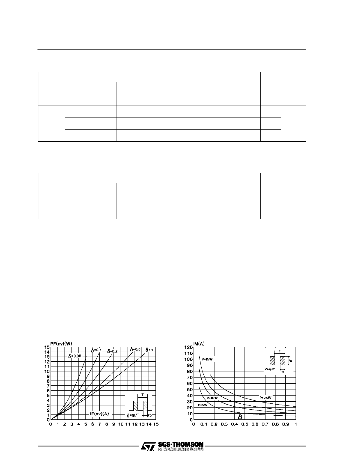
To evaluate the conduction losses use the following equation:
P = 0.78 x I
Tj = 25°CI
+ 0.0175I
F(AV)
F2(RMS)
= 0.5 A IR= 1A Irr =0.25 A 30 ns
F
= 1 A tr = 10 ns VFR= 1.1 x V
F
= 1 A tr = 10 ns 3 V
F
F
20 ns
age forward current.
2/6
Fig.2 : Peak current versus form factor.Fig.1 : Average forward power dissipation versus aver-
Page 3

STPR1210 D/F / S T PR1220 D/F
Fig.3 : Average current versus ambient temperature.
(duty cycle : 0.5) (TO220AC)
Fig.5 : Non repetitive surge peak forward current versus
overload duration.
(Maximum values) (TO220AC)
Fig.4 : Average current versus ambient temperature.
(duty cycle : 0.5) (ISOWATT220AC)
Fig.6 : Non repetitive surge peak forward current versus
overload duration.
(Maximum values) (ISOWATT220AC)
Fig.7 : Relative variation of thermal transient impedance
junction to case versus pulse duration.
(TO220AC)
Fig.8 : Relative variation of thermal transient impedance
junction to case versus pulse duration.
(ISOWATT220AC)
3/6
Page 4

STPR1210D/F / STPR1220D/F
Fig.9 : Forward voltage drop versus forward current.
(Maximum values)
Fig.11 : Recovery charge versus dIF/dt. Fig.12 : Peak reverse current versus dIF/dt.
Fig.10 : Junction capacitance versus reverse voltage
applied. (Typical values)
Fig.13 : Dynamic parameters versus junction temperature.
4/6
Page 5

PACKAGE MECHANICAL DATA
TO220AC (JEDECoutline)
A
I
P
N
G
D
E
F
O
STPR 1210D/F / STP R1220 D/F
DIMENSIONS
H
J
REF.
A 10 10.4 0.393 0.409
B 15.2 15.9 0.598 0.626
C 13 14 0.511 0.551
K
B
D 6.2 6.6 0.244 0.260
E 16.4 typ. 0.645 typ.
F 3.5 4.2 0.137 0.165
G 2.65 2.95 0.104 0.116
H 4.4 4.6 0.173 0.181
L
C
I 3.75 3.85 0.147 0.151
J 1.23 1.32 0.048 0.051
K 1.27 typ. 0.050 typ.
L 0.49 0.70 0.019 0.027
M
M 2.4 2.72 0.094 0.107
N 4.95 5.15 0.194 0.203
O 1.14 1.70 0.044 0.067
P 0.61 0.88 0.024 0.034
Millimeters Inches
Min. Max. Min. Max.
Cooling method : C
Marking : Type number
Weight : 1.9 g
Recommended torque value : 0.55m.N
Maximum torque value : 0.7m.N
PACKAGE MECHANICAL DATA
ISOWATT220AC (JEDECoutline)
A
I
B
D
C
O
P
N
H
J
REF.
Millimeters Inches
DIMENSIONS
Min. Max. Min. Max.
A 10 10.4 0.393 0.409
B 15.9 16.4 0.626 0.645
C 28.6 30.6 1.126 1.204
E
L
M
D 16 typ 0.630 typ
E 9 9.3 0.354 0.366
H 4.4 4.6 0.173 0.181
I 3 3.2 0.118 0.126
J 2.5 2.7 0.098 0.106
L 0.4 0.7 0.015 0.027
M 2.4 2.75 0.094 0.108
N 4.95 5.2 0.195 0.204
O 1.15 1.7 0.045 0.067
P 0.75 1 0.030 0.039
Cooling method : C
Marking : Type number
Weight : 2 g
Recommended torque value : 0.55m.N
Maximum torque value : 0.70m.N
Electrical Isolation : 2000V DC
Capacitance : 12pF
5/6
Page 6

STPR1210D/F / STPR1220D/F
Information furnishedis believed to be accurate and reliable. However, SGS-THOMSON Microelectronics assumes no responsability for the
consequences of useof such information nor forany infringement of patents or other rights of third parties which may resultsfrom its use. No
license is granted byimplication or otherwise under any patent orpatent rights of SGS-THOMSONMicroelectronics. Specificationsmentioned
in this publication are subject to change without notice. This publication supersedes and replaces all information previously supplied.
SGS-THOMSON Microelectronicsproductsarenot authorizedfor use ascritical components inlife support devicesor systems withoutexpress
written approvalof SGS-THOMSONMicroelectonics.
1994 SGS-THOMSON Microelectronics - All Rights Reserved
TURBOSWITCH, TRANSIL, TRISIL, SNUBBERLESS are Trademarksof SGS-THOMSON Microelectronics.
Australia -Brazil - France - Germany- Hong Kong - Italy - Japan - Korea - Malaysia - Malta - Morocco - The Netherlands -
Singapore - Spain - Sweden - Switzerland - Taiwan - Thailand - United Kingdom -U.S.A
SGS-THOMSON Microelectronics GROUP OF COMPANIES
6/6
 Loading...