

Page 1
INTEGRATED CIRCUITS
SA5778
Serial triple gauge driver (STGD)
Product specification
Supersedes data of 1997 May 27
IC18 Data Handbook
1998 Apr 03
Page 2
Philips Semiconductors Product specification
SA5778Serial triple gauge driver (STGD)
DESCRIPTION
The Serial Triple Gauge Driver (STGD), is a single chip air core
driver providing drive to one major gauge, and two minor gauges, for
automotive applications such as Speedometer, Fuel, Temperature,
Tachometer, Volts, and Oil pressure information display. The STGD
operates in conjunction with a microcontroller receiving serial data
inputs, and can provide status back to the microcontroller either
serially or via a status line. The protocol is compatible with the
Philips Single Gauge Driver (SGD) and Dual Gauge Driver (DGD).
The STGD also includes a protected battery supply for external
single Serial Gauge Drivers or Dual Gauge Drivers.
PIN CONFIGURATION
SIN+
1
RUN
2
GOE
3
SwCONTROL
SwBATT1
SwBATT2
DATA
4
5
GND GND
6
GND
7
GND GND
821
GND GND
9
V
10
BATT
11
12
OUT
COM
13
C2–
14
SIN–
28
COS+
27
26
COS–
ST
25
24
S
CLK
23
GND
22
20
CS
19
DATA
18
IN
C1–
17
C1+
16
C2+
15
FEATURES
•Major Gauge 10-bit resolution Drive provides 0.35° resolution
– Sine/Cosine outputs for 360° operation
– 0.2° accuracy typical throughout entire range
•Minor gauge drivers provide 0.35° resolution
– 112° operation
– 0.5° accuracy typical throughout entire range
•Serial Data Input
– Supports interface from microcontrollers
– Compatible with Philips SGD SA5775A and DGD SA5777A
•Serial Data Output
– Permits the STGD to be wired in series using a common chip
select to additional STGDs, SGDs, and DGDs
– Permits fault status information to be returned to the
microcontroller
•Over Voltage Protection, Over Temperature Protection and Low
Standby Current Operation
– Gauge drivers disabled when supply voltage exceeds specified
operating voltage, protection to 40V .
– Gauge drivers disabled when die temperature exceeds
operating range
– External switch may supply overvoltage protected battery
supply to other devices operating off battery
•Thermally Enhanced SO-28 surface mount package
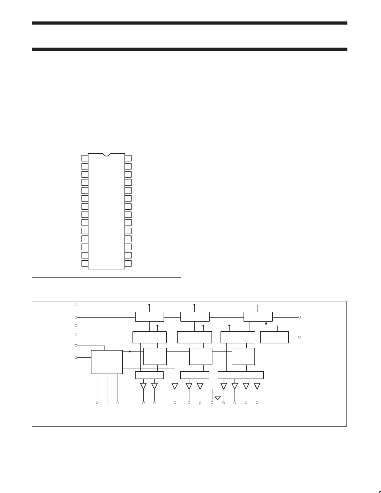
Figure 1. Pin Configuration
BLOCK DIAGRAM
S
CLK
DATA
IN
CS
GOE
RUN
V
BATT
BIAS, TSD
SwBATT,
COMMON
REFERENCE
SwBATT1
SwControl
SR01116
MINOR GAUGE 2
10-BIT SR 10-BIT SR 10-BIT SR
9-BIT DATA
ENABLE
SwBATT2
MINOR GAUGE 1 MAJOR GAUGE
LATCH
7-BIT
MUX
C2–
Tan
DAC
C2+
9-BIT DATA
LATCH
7-BIT
Tan
DAC
MUX MUX
C1–
COM
C1+
GND
10-BIT DATA
LATCH
COS–
Figure 2. STGD Internal Block Diagram
7–BIT, SINE
/COSINE
DAC
SIN–
COS+
4-BIT STATUS
LATCH
SIN+
DATA
ST
OUT
SR01117
1998 Apr 03 853–2055 19199
2
Page 3
Philips Semiconductors Product specification
Á
Á
Á
Á
Á
Á
Á
Á
Á
Á
Á
Á
Á
Á
Á
Á
Á
Á
Á
Á
Á
Á
Á
Á
Á
Á
Á
Á
Á
Á
SA5778Serial triple gauge driver (STGD)
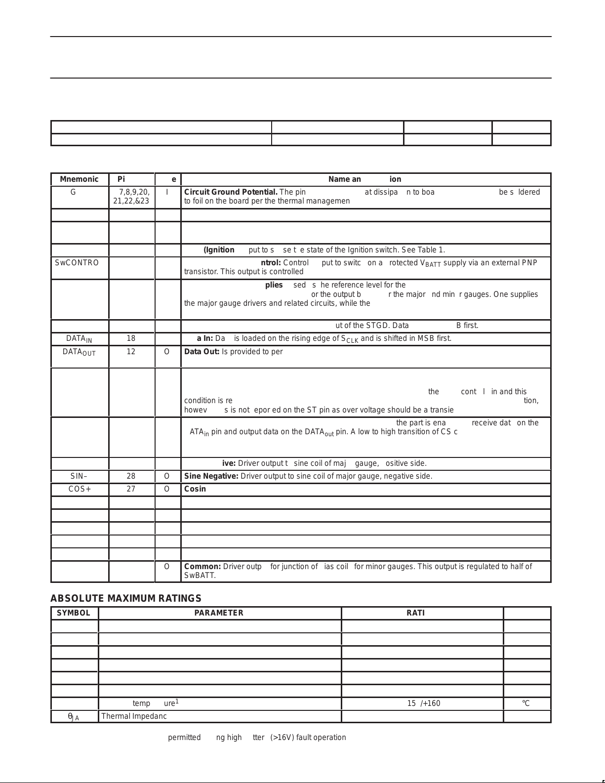
ORDERING INFORMATION
DESCRIPTION TEMPERATURE RANGE ORDER CODE DWG #
28-Pin Small Outline (SO) thermally enhanced Package –40 to +105°C SA5778D SOT136-1
PIN DESCRIPTION
Mnemonic
GND
V
BATT
GOE
ÁÁÁ
RUN
SwCONTROL
ÁÁÁ
SwBATT1
SwBATT2
ÁÁÁ
ÁÁÁ
S
CLK
DATA
IN
DATA
OUT
ÁÁÁ
ST
ÁÁÁ
ÁÁÁ
CS
ÁÁÁ
ÁÁÁ
SIN+
SIN–
COS+
COS–
C1+
C1–
C2+
C2–
COM
ÁÁÁ
Pin No.
6,7,8,9,20,
21,22,&23
10
3
ÁÁ
2
4
ÁÁ
5,
11
ÁÁ
ÁÁ
24
18
12
ÁÁ
25
ÁÁ
ÁÁ
19
ÁÁ
ÁÁ
1
28
27
26
16
17
15
14
13
ÁÁ
Type
I
Circuit Ground Potential. The pins are used for heat dissipation to board. All pins should be soldered
Name and Function
to foil on the board per the thermal management description.
I
Battery supply voltage
I
Gauge Output Enable: A high on this input enables normal operation of the gauge coil drivers.
See Table 1.
ББББББББББББББББББББББББ
I
RUN (Ignition): Input to sense the state of the Ignition switch. See Table 1.
O
Switched Battery Control: Control output to switch on a protected V
ББББББББББББББББББББББББ
transistor. This output is controlled by the RUN input, GOE input and the on chip protection circuits.
I
Switched Battery Supplies: Used as the reference level for the DACs, bias voltage for the second coils
I
of the minor gauges, and the supply for the output buffers for the major and minor gauges. One supplies
ББББББББББББББББББББББББ
the major gauge drivers and related circuits, while the other supplies the minor gauge circuits. Both
SwBATT inputs must be connected to the control transistor as the two inputs are not connected internally.
ББББББББББББББББББББББББ
I
Serial Clock: Used to clock data into and out of the STGD. Data is shifted MSB first.
I
Data In: Data is loaded on the rising edge of S
O
Data Out: Is provided to permit the STGD to pass status information back to the controlling
microcontroller, and to allow multiple devices to be connected in series.
ББББББББББББББББББББББББ
O
Status Output: This is an open drain output. Status outputs from several devices may be wire OR’ed
and is shifted in MSB first.
CLK
supply via an external PNP
BATT
together. This output is low when the outputs are disabled due to a fault condition. The outputs may be
disabled due to shorted outputs, over temperature, power up reset, or the GOE control pin and this
ББББББББББББББББББББББББ
condition is reflected on the ST pin. The outputs will also be disabled due to an over voltage condition,
ББББББББББББББББББББББББ
however this is not reported on the ST pin as over voltage should be a transient condition.
I
Chip Select: Active high chip select input. When CS is high, the part is enabled to receive data on the
pin and output data on the DATA
DATA
in
ББББББББББББББББББББББББ
the shift register for output. A high to low transition of CS loads gauge data from the shift register into
the data latches.
ББББББББББББББББББББББББ
O
Sine Positive: Driver output to sine coil of major gauge, positive side.
O
Sine Negative: Driver output to sine coil of major gauge, negative side.
O
Cosine Positive: Driver output to cosine coil of major gauge, positive side.
O
Cosine Negative: Driver output to cosine coil of major gauge, negative side.
O
Coil 1 Positive: Driver output to driven coil of minor gauge 1, positive side.
O
Coil 1 Negative: Driver output to driven coil of minor gauge 1, negative side.
O
Coil 2 Positive: Driver output to driven coil of minor gauge 2, positive side.
O
Coil 2 Negative: Driver output to driven coil of minor gauge 2, negative side.
O
Common: Driver output for junction of bias coils for minor gauges. This output is regulated to half of
ББББББББББББББББББББББББ
SwBATT.
pin. A low to high transition of CS captures device status in
out
ABSOLUTE MAXIMUM RATINGS
SYMBOL
V
VIN1
VIN2
VIN3
T
BATT
P
amb
T
θ
Battery supply voltage, with recommended 1K series resistor
Input voltage; Data In, CS, SCLK, GOE
Input voltage; Sw
BATT
Input voltage; RUN, with recommended RC Circuit
Power Dissipation (T
D
Ambient operating temperature
Junction temperature
J
Thermal Impedance
JA
NOTE:
1. 160°C junction temperature is permitted during high battery (>16V) fault operation
1998 Apr 03
PARAMETER
= 105°C) SO-28 Package
amb
1
3
RATING
40
–1 to +7
–1 to +24
–1 to +40
1400
–40 to +105
+150/+160
See Thermal Management Section
UNIT
V
V
V
V
mw
°C
°C
°C/W
Page 4

Philips Semiconductors Product specification
SYMBOL
PARAMETER
TEST CONDITION
UNITS
Á
Á
Á
Á
Á
Á
Á
Á
Á
Á
Á
Á
Á
Á
Á
Á
SYMBOL
PARAMETER
TEST CONDITION
UNITS
SA5778Serial triple gauge driver (STGD)
DC ELECTRICAL CHARACTERISTICS
V
= 8.0 to 16V; T
BATT
V
BATT
V
SWBATT
I
BATT
I
SWBATT
I
BATTSB
V
OH1
V
OH2
I
OH
V
OL1
V
OL2
V
IH
V
IL
V
OVSD
I
ÁÁ
IH
I
IL
ÁÁ
ACC1
ACC2,3
V
DRIVE1
ÁÁ
V
DRIVE2,3
R
LMIN
V
COM
Battery supply voltage
Switched battery supply voltage
Battery supply current, operating
Switched battery supply current, operating
Battery supply current, standby
Output high voltage
Output high voltage
Off state output current
Output low voltage
Output low voltage
Input high voltage
Input low voltage
Battery overvoltage shutdown voltage
Input high current
БББББББББ
Input low current
БББББББББ
Output function accuracy, major gauge
Output function accuracy, minor gauges
Coil drive voltage, major gauge
БББББББББ
Coil drive voltage, minor gauges
Minimum coil load resistance
Minor gauge bias voltage
= –40 to +105°C
amb
MIN
Normal operating range
Normal operating range
V
= V
BATT
RL = R
BATTMAX
LMIN
8
7.5
Normal operating range
V
= 12 V
BATT
DATA
SwCONTROL, IOH = 10µA
, IOH = 300µA
OUT
4.0
40
ST, VOH = 5 V
ST, DATA
, IOL = 1.5 mA
OUT
SwCONTROL,
IOL = 50 mA @ V
IOL = 20 mA @ V
CS, SCLK, DATAIN, GOE, RUN
BATTMAX
BATTMIN
3.5
CS, SCLK, DATAIN, GOE, RUN
V
BATT
CS, SCLK, DATAIN, RUN GOE;
ББББББББ
V
= 3.5
IH
18
ÁÁÁÁÁÁÁ
CS, SCLK, DATAIN, RUN GOE;
=1.5
V
IL
ББББББББ
RL = R
RL = R
ББББББББÁÁÁ
; major gauge, G1
LMIN
; minor gauges, G2 & G3
LMIN
ÁÁÁÁÁÁÁ
–0.5
–1.0
68
70
T
= 105°C
amb
T
= 25°C
amb
T
= –40°C
amb
IOB (Source or Sink)
R
= R
L
LMIN
226
171
127
0.475 ×
Sw
BATT
LIMITS
TYP
71
ÁÁ
74
MAX
16
16
0.5
400
60
25
0.4
1.5
1.2
1.5
23
10
10
+0.5
+1.0
78
Á
80
0.525 ×
Sw
BATT
V
V
ma
ma
µA
V
V
µA
V
V
V
V
V
V
µA
ÁÁ
µA
ÁÁ
Deg
Deg
%
ÁÁ
Sw
BATT
%
Sw
BATT
Ω
Ω
Ω
V
AC ELECTRICAL CHARACTERISTICS
V
BATT
F
t
SCLKL
t
SCLKH
1998 Apr 03
= 7.5 to 16V; T
t
CYC
SCLK
Clock cycle time
Clock frequency
SCLK LOW time
SCLK HIGH time
t
CSH
t
CSL
t
t
t
t
CS high to SCLK high time
SCLK low to CS low time
DATAIN setup to SCLK high time
SU
SCLK high to DATAIN hold time
HD
DATAOUT rise time
DR
DATAOUT fall time
DF
= –40 to +105°C
amb
T
CYC
0.8 to 3.6V; CL = 90pF
3.6 to 0.8V; CL = 90pF
4
MIN
625
175
175
75
75
75
75
LIMITS
TYP
MAX
1.60
75
75
ns
MHz
ns
ns
ns
ns
ns
ns
ns
ns
Page 5

Philips Semiconductors Product specification
SA5778Serial triple gauge driver (STGD)
J1850
PROTOCOL
CONTROLLER
AU5780
J1850 VPW
TRANSCEIVER
J1850 BUS
80C51
MICRO–
CONTROLLER
ADDITIONAL GAUGE
DRIVERS; SA5775A
OR SA5777A
PROTECTED BY
SA5778
Figure 3. System Connections for the STGD
FUNCTIONAL DESCRIPTION
Figure 1 shows the pin-out of the STGD, which is packaged in an
SO-28 pin package, enhanced for improved thermal management.
Four pins on each side of the package serve as a heat spreader to
remove heat from the die, and also function as the ground
connection. The recommended mounting includes an area of copper
on the PC board to aid in thermal management.
Figure 2 is a block diagram of the STGD. A serial interface connects
the STGD to the microcontroller. A data output pin is provided to
permit the STGD to be wired in series with other Philips air core
gauge drivers such as the Serial Gauge Driver, SA5775, and the
Dual Gauge Driver, SA5777 or additional STGDs. Status information
may be passed back to the microcontroller via a status output, or via
the serial interface.
Figure 3 shows the connection of the STGD in a typical application.
GOE
SERIAL
SA5778
SERIAL
TRIPLE
GAUGE
DRIVER
MICROCONTROLLER
DATA
PORT N
DATA
5V
S
OUT
CLK
INT
4
2
2
V
IN
RUN
IGNITION
BATT
360° MAJOR
GAUGE
112° MINOR
GAUGE
SR01118
DATA
IN
S
CLK
CS
DATA
OUT
ST
DATA
IN
S
CLK
CS
DATA
OUT
ST
SA5778 SERIAL
TRIPLE
GAUGE DRIVER
ADDITIONAL
GAUGE DRIVER(S),
SA5775A,
SA5777A OR
SA5778
APPLICATION INFORMATION
Figure 4 demonstrates the connections between the STGD, the
microcontroller, and optionally additional gauge drivers such as the
SGD and DGD. With an active high on the chip select input (CS),
data is shifted into the STGD through DATA
. Several gauge drivers may be wired in series using a
S
CLK
common chip select and clock line, when more than three gauges
are needed. The DATA
pins are cascaded to the DATAIN pins of
OUT
the following gauge drivers. Status information can be returned to
the microcontroller via the ST pins of each gauge driver. These are
open-drain, active low outputs, which may be wire OR’ed together to
signal that a fault, such as a thermal shut down, has occurred within
one of the gauge drivers. This pin may be connected to a
microcontroller port pin for polling in software, or may be connected
to an external interrupt input to cause entry into an interrupt service
routine. The STGD, may also pass status information back to the
microcontroller serially. The rising edge of chip select loads status
information into the shift register for the first four bits that will be
shifted out of the STGD by the shift clock. Figure 11 shows the data
bits within the shift register. A low on the ST pin signals that one or
more status bits have been set in the status register. A high
indicates all status bits are reset. The status output bits include
minor gauge over current, major gauge over current, thermal
shutdown and RUN. Gauge data is captured in latches by the falling
edge of the chip select.
on the rising edge of
IN
SR01119
Figure 4. Serial Communications Between STGD,
Microcontroller and Other Gauge Drivers
Figure 5 shows the gauge connections to the STGD. The major
gauge, G1, supports full 360° operation with two coils driven. The
seven least significant bits of the gauge information are converted to
an analog level by digital-to-analog converter. The display range is
divided into eight sections, two sections per quadrant. The coils are
driven with a Sine/Cosine approximation. The three most significant
bits of gauge display information control the multiplexer to select
which coil is fed by the DAC and which coil receives a fixed bias.
The multiplexer also determines the polarity of the voltages supplied
to the coils.
The minor gauges, G2 and G3, each have one coil driven by a DAC.
The other coils of each gauge are wired in series with the switched
battery supply to supply the bias. The switched battery supply is
turned off during over voltage conditions. Only 9-bits of information
are required for the minor gauges, however, 10-bits are shifted
through the part to maintain compatibility with the SGD and DGD.
Hence, all gauges, both major and minor, are supplied with 10-bit
data for consistency.
1998 Apr 03
5
Page 6

Philips Semiconductors Product specification
SA5778Serial triple gauge driver (STGD)
placed in a standby mode with a low on both the GOE and RUN
DATA
IN
S
CLK
ST
CS
GOE
PROTECTION
SwBATT, BIAS
SwControl
SwBATT TRANSISTOR
V
BATT
RUN
THERMAL
DATA / STATUS SHIFT REGISTERS
STATUS
LATCH
DIGITAL-to-ANALOG
CONVERTERS and OUTPUT
MULTIPLEXERS
ENABLE
C2–
C2+
COM
SwBATT2
SwBATT1
C1–
LATCHES
C1+
DATA
GND
COS–
360° MAJOR GAUGE112° MINOR GAUGES
COS+
SIN–
DATA
OUT
SIN+
SR01120
Figure 5. Gauge Connections to the STGD
18-24V
REFERENCE
V
BATT
1KΩ
GOE
RUN
10KΩ
+
–
R
B
V
BATT
5V
REGULATOR
OUTPUT
BUFFER SUPPLY
DAC REFERENCES
SwBATT1/2SwControl
BIAS COILS
EXTERNAL
GAUGE DRIVERS
5V
LOGIC
SR01121
Figure 6. Gauge Enable/Standby Circuit and Over Voltage
Protection Circuit
Figure 6 shows the protection and gauge enable logic for the STGD.
The battery supply voltage V
is monitored, and if the supply
BATT
exceeds the specified operating range, the STGD is put in a
shutdown mode in which the output buffers are disabled. The STGD
will also enter the shutdown mode by excessive die temperature,
and will return to normal operation when the die temperature
decreases to within specified limits. Thermal shutdown may occur at
V
supply voltages over 16V at high ambient temperatures near
BATT
105°C. Internal logic will continue to function and status may be read
out to determine the source of the shutdown. The STGD may be
input pin. In this mode, battery current drain is minimized.
The SwBATT1 and SwBATT2 inputs are the supply for the DACs,
and the output buffers driving the coils including the COM output
which stabilizes the voltages applied to the bias coils of the minor
gauges. Both SwBATT1 and SwBATT2 should be connected to the
collector of the control transistor as these inputs are not connected
internally and supply different portions of the circuit. This switched
battery supply is protected from voltages exceeding the specified
operating range and is controlled by the SwCONTROL output. This
supply may optionally be used to supply additional circuits which
operate from unregulated battery supplies but which need protection
from over voltage transients. Typical devices which may benefit from
this protection include the Serial Gauge Driver, SA5775A and Dual
Gauge Driver, SA5777A, which are often used in conjunction with
the STGD in 4 and 5 gauge applications.
This switched battery supply is turned off when the STGD enters the
standby mode in response to the RUN and GOE inputs both being
low, or a V
supply exceeding the specified operating range. The
BATT
switched battery supply depends on the RUN signal to prevent
undesired needle movement on the minor gauges when going from
standby to active mode. This movement would otherwise occur if
the voltage to the fixed bias coils of the minor gauges was switched
on before the coil voltages provided by the DACs within the STGD
were defined. The start up jump is prevented as follows. In the sleep
mode the switched battery supply is off, and the gauge drive outputs
of the STGD are in a high impedance state. The gauges are in their
zero position from the previous power-down sequence. When the
RUN input goes high, but the GOE is kept low, the STGD enters the
start up mode in which the minor gauges are driven to zero, the
internal 5V regulator for the logic is turned on, and the switched
battery supply is turned on to supply the bias coil and STGD output
buffers. However , the output buf fers for the major gauge remain in
the high impedance output state. The microcontroller may load
values into the STGD via the serial interface while GOE is low.
When the microcontroller applies a high to GOE, the major gauge
output buffers are enabled. When the RUN signal is removed the
STGD continues to operate in the normal mode, however, the
controlling microcontroller should also monitor RUN and, when it
goes low, send a series of values to the STGD to move the needles
to their zero positions before taking GOE low to put the part in the
standby mode.
Table 1 describes the operation and control of the SwBATT supply,
the output buffers, and the operations normally performed by the
microcontroller. Normal operation of a vehicle will follow the
sequence of the truth table from top to bottom. The RUN input is
typically connected to the switched ignition voltage, while GOE is
controlled by the microcontroller.
1998 Apr 03
6
Page 7

Philips Semiconductors Product specification
Á
Á
Á
Á
Á
Á
Á
Á
Á
Á
Á
Á
Á
Á
Á
Á
Á
Á
Á
Á
Á
Á
Á
Á
Á
Á
Á
Á
Á
Á
Á
Á
Á
Á
Á
Á
Á
Á
Á
Á
Á
Á
Á
Á
Á
Á
Á
Á
Á
SA5778Serial triple gauge driver (STGD)
Table 1. Truth Table
RUN
ÁÁ
Input
1=High
ÁÁ
0
ÁÁ
1
ÁÁ
1
ÁÁ
0
ÁÁ
0
ÁÁ
GOE
Á
Input
1=High
Á
0
Á
0
Á
1
Á
1
Á
0
Á
SwControl
ÁÁÁ
1=ON
ÁÁÁ
0
ÁÁÁ
1
ÁÁÁ
1
ÁÁÁ
1
ÁÁÁ
0
ÁÁÁ
Swbatt1,2
ÁÁ
Voltage
ÁÁ
Off
ÁÁ
V
BATT
ÁÁ
V
BATT
ÁÁ
V
BATT
ÁÁ
Off
ÁÁ
Minor Gauge Driver
БББББ
Outputs
БББББ
High Impedance
Enabled
БББББ
(output forced to zero)
БББББ
Enabled
БББББ
Enabled
БББББ
High Impedance
БББББ
Major Gauge
ÁÁÁ
Driver Outputs
ÁÁÁ
High
Impedance
High
ÁÁÁ
Impedance
ÁÁÁ
Enabled
ÁÁÁ
Enabled
ÁÁÁ
High
Impedance
ÁÁÁ
ББББББББББ
ББББББББББ
System Status
Standby mode
Start up mode, sets minor gauge driver to
zero position, and disables major gauge
ББББББББББ
driver. Load values into STGD via the serial
ББББББББББ
port.
Normal Operating mode. Periodically
update gauge data as required by the
ББББББББББ
application.
Power down sequence. Load a series of
values into the STGD to return needles to
ББББББББББ
zero before power is removed.
Returned to standby mode (same as first
row of table)
ББББББББББ
THERMAL MANAGEMENT AND POWER
DISSIPATION
The power dissipated by the STGD has three components. The first
term in the equation below represents the power dissipated in the
STGD from current through the coil resistance. This component of
the power dissipation is a function of both the battery voltage and
the coil resistance. Most of the external loads such as the coils are
resistive, so the current drawn by the output buffers is proportional
to the supply voltage, resulting in power dissipation that is
proportional to the square of the supply voltage for these circuits.
The highest power dissipation for a given coil driver will occur when
the coil voltage is being driven to 50% of V
dissipated by each coil driver is (V
V
BATT(VBATT
/4Rc). If the coil resistance of the two minor gauge coils
BATT
and the two coils of the major gauge all have the same resistance,
then the maximum total power dissipation of the drivers becomes
4*V
BATT(VBATT
/4Rc) or simply V
BATT(VBATT
internal analog circuits appears to the supply pins as a current sink
and is represented by the second term. The current drawn by these
circuits is relatively constant despite changes in supply voltage,
resulting in power dissipation that is proportional to the supply
voltage. Finally some power is dissipated in driving the external PNP
transistor used to control the switched battery supply. The total
power dissipation is a combination of these components and may be
calculated from the formula:
P
D=VBATT(VBATT/RC
V
OL2(VBATT–VOL2–VBE(PNP)
)+V
BATT
(0.012) +
)/R
B
Where:
= Power dissipation in watts
P
D
= Battery supply voltage in volts
V
BATT
RC = Coil resistance in ohms at ambient temperature including
any self heating effects
V
= Output low voltage of the SwCONTROL pin as specified
OL2
in the DC Characteristics
V
= The VBE drop of the external PNP transistor
BE(PNP)
RB = Resistor is series with base of external PNP transistor.
The minimum value of R
B
= V
BATTMAXIOL
. Thus the power
BATT
/2)* (V
BATT
/Rc). Much of the
=16/0.050=320 Ω
/2Rc) or
The actual value used is dependent on the current needed to
keep the PNP in saturation.
All gauges at 45° to a quadrant axis, as this is the highest
internal power dissipation position.
If only the nominal coil resistance is known at a given nominal
ambient temperature such as 25°C, the coil operating resistance at
a high temperature ambient may be calculated using the following
formula:
R
CA
= R
(1+(0.4%/°C)*((TSH+T
CN
amb
)–25°C))
Where:
RCA = Resistance of Coil at Ambient temperature, including self
heating
= Nominal Resistance of Coil at 25°C, without self heating
R
CN
T
= Ambient temperature, °C
amb
TSH = Self heating of coil, °C
0.4%/°C = Resistance increase coefficient for copper
Figure 7 shows power dissipation plotted as a function of coil
resistance and voltage. Since coil resistance is a function of
temperature, the maximum power dissipation plotted will only occur
at the lowest specified operating temperature. The power dissipation
is lowest at the highest ambient temperature because of the
increase in coil resistance with temperature.
This maximum power dissipation will only occur during a fault
condition in which the system voltage rises to 18V , generally
because of a failed voltage regulator controlling the vehicles battery
voltage. Power dissipation will be lower when air core meter
movements with higher nominal coil resistance are used.
1998 Apr 03
7
Page 8

Philips Semiconductors Product specification
SA5778Serial triple gauge driver (STGD)
POWER
(W)
3.0
POWER DISSIPATION FOR COIL
2.5
2.0
1.5
1.0
0.5
0.0
7.5
8
RESISTANCE IN OHMS AND OP-
ERATING BATTERY VOLTAGE
8.5
9
9.5
10
10.5
11
11.5
12
12.5
13
13.5
14
14.5
15
15.5
16
V
SWBATT
(V)
Figure 7. Power Dissipation of the STGD as a Function of Coil Resistance and Operating Voltage
16.5
125
150
175
235
325
LOAD RESISTANCE
(Ω)
17
17.5
18
SR01430
The STGD is specified to operate up to V
max. The over voltage
BATT
shutdown circuit will turn off the output buffers and the switched
battery supply when the battery voltage reaches V
OVSD.
Over
temperature conditions will also cause the output buffers to be
disabled.
The STGD employs a thermally enhanced SO-28 package. The
center four pins on each side are fused to the die pad to create a
path for removal of heat from the package to the copper foil on the
PC board. An area of copper foil is required on the PC board for
heat dissipation at higher power dissipation levels.
In order to determine the size of the copper foil required, both
thermal testing and thermal modeling were used. The effective
Θ
(thermal resistance, junction to ambient) was determined using
JA
both single and double sided PCBs with heat-sinking copper foil
areas. Figures 8 and 9 show the effect of PCB copper foil area on
the effective thermal resistance of the STGD part/PCB system.
Figure 8 shows the thermal resistance of the STGD mounted on a
PC board with heat-sinking copper on the component side only.
Figure 9 is a similar plot for a two sided PC board (same size copper
areas on each side). Both plots assume a 60 x 60 x 1.57 mm FR4
board with varying square-shaped sizes of 2 oz. copper. The two
sided board also assumes 8 thermal bias with 0.36 mm
2
cross
section.
It is important to note that at such a high ambient temperature (worst
case of 105°C assumed), radiation is just as significant as
convection in the dissipation of heat. Good radiation is highly
dependent on the emissivity of the heated surface, so the thermal
radiation properties of the copper foil should be considered. Bare,
clean copper is a good thermal conductor, but it has a low emissivity ,
and is therefore a bad radiator. It is recommended that the copper
areas intended for heat dissipation be left covered with solder mask
or otherwise blackened to increase the emissivity, thereby improving
the heat radiating ability of the board.
1998 Apr 03
8
Page 9

Philips Semiconductors Product specification
SA5778Serial triple gauge driver (STGD)
50
ΘJA (°C/W)
45
ΘJA (°C/W)
40
35
30
25
0 500 1000 1500 2000 2500 3000 3500
1.4W LIMIT
PCB COPPER HEAT SINK AREA (SQ mm)
Figure 8. θJA for SO28 with 8 Fused Pins
One-sided PCB (2 oz. Copper), e = 0.9, T
45
40
1.4W LIMIT
= 105°C, P = 1.4–1.8W
amb
SR01497
1998 Apr 03
35
30
25
0 500 1000 1500 2000 2500 3000
PCB COPPER HEAT SINK AREA (SQ mm)
Two-sided PCB (2 oz. Copper), e = 0.9, T
Figure 9. θ
for SO28 with 8 Fused Pins
JA
= 105°C, P = 1.4–1.8W
amb
9
SR01498
Page 10

Philips Semiconductors Product specification
SA5778Serial triple gauge driver (STGD)
Sample Calculations for Power Dissipation and
Thermal Management
Worst Case Example
The worst case example will occur when the STGD is operating at
V
BATTMAX
(105°C), and with the lowest specified coil resistance (171 ohms at
25°C). Typical coil self heating of 15°C is assumed.
Calculation of Coil resistance operating at 105°C ambient.
Calculation of STGD power dissipation at 16 volt operation.
Required board area and Junction Temperature calculation
The maximum junction temperature desired is 150°C. The
permissible temperature rise and required Θ
as:
Where; ∆T = Temperature rise in °C
(16V , in the highest specified ambient temperature
R
= RCN (1+(0.4%W/°C)*((TSH+T
CA
amb
)–25°C))
= 171 x(1+(0.4%((15+105)–25)))
= 236 Ohms at T
PD= V
BATT
(V
+V
OL2
(V
BATT
BATT/RC
=105°C, with 15°C of self heating.
amb
– V
)+ V
OL2
– V
(0.012)
BATT
BE(PNP)
) / R
L
= 16(16/236)+16(0.012)+1.5(16–1.5–0.5)/320
= 1.085+0.192+0.066 Watts
= 1.34 Watts
JA
∆T = T
j–Tamb
ΘJA = ∆T/P
D
PD = Power dissipation
Tj = Junction Temperature
= Ambient Temperature
T
amb
∆T = TJ–T
= 150 – 105 = 45°C
amb
ΘJA = ∆T/PD=55°C/1.34 watts = 33°C/W.
may be calculated
From Figure 8, the copper area required, using a single sided board,
to keep the junction temperature within limits is approximately
2200 mm
2
. Figure 9 shows 1200 mm2 is required on each side of a
double-sided board.
The above example illustrates the worst case situation of the STGD
operating in at a maximum battery voltage, with the lowest nominal
coil resistance (171Ω at room temperature), and at the highest
ambient temperature. This will produce the highest junction
temperature. At lower ambient temperatures the power dissipation
may be higher because the coil resistance is decreased, however
the junction temperature will be lower.
Serial Interface
Figure 10 demonstrates the serial interface timing referenced in the
AC specifications. Figure 11 shows the order of information transfer
through the serial interface. On a low to high transition of the CS pin,
status information replaces the four most significant bits of data in
the shift register and are the first bits shifted out. Output data is
changed on the falling edge of S
the rising edge of S
. Major gauge data is loaded first, starting
CLK
with the most significant bit, followed by minor gauge 1 data then
minor gauge 2 data.
, while input data is captured on
CLK
1998 Apr 03
DATA
DATA
t
CYC
t
CF
t
S
CLK
CS
IN
OUT
CSH
t
SU
12930
D29 D1 D0*
t
DR
S4 D1* D0*
t
CR
30 CLOCK CYCLES
t
HD
t
CSL
t
SCLKL
t
DF
t
SCLKH
SR01499
Figure 10. Serial Interface Timing
10
Page 11

Philips Semiconductors Product specification
SA5778Serial triple gauge driver (STGD)
MINOR GAUGE 2 MINOR GAUGE 1 MAJOR GAUGE/STATUS
D0 D1 D2 D3 D4 D5 D6 D7 D8 D9 D10 D11 D12 D13 D14 D15 D16 D17 D18 D19 D20 D21 D22 D23 D24 D25 D26 D27 D28 D29
During Read out:
D26: RUN Input State; 1 = RUN input high
0 = RUN input low
D27: Thermal Shutdown; 1 = Shutdown
0 = Normal operation
D28: Minor Gauge Over Current; 1 = Over Current Shutdown
0 = Normal operation
D29: Major Gauge Over Current; 1 = Over Current Shutdown
0 = Normal operation
Figure 11. Internal Shift Register
15
DATA OUTDATA IN
MSBMSBMSB LSBLSBLSB
SR01123
COS
10
5
0
0 127 255 383 511 639 767 895 1023
–5
DIFFERENTIAL OUTPUT VOLTAGE
–10
–15
Figure 12. Major Gauge Output Voltages (V
SIN
INPUT CODE
SWBATT
= 14V)
SR01500
1998 Apr 03
11
Page 12

Philips Semiconductors Product specification
SA5778Serial triple gauge driver (STGD)
14.00
12.00
10.00
8.00
6.00
4.00
2.00
0.00
–2.00
C+ – C– (VOLTS)
–4.00
–6.00
–8.00
–10.00
–12.00
–14.00
Figure 13. Typical Minor Gauge Output Voltage vs. Input Code (V
31 63 95 127 159 191 223 255 287 319
INPUT CODE
SL00462
= 14V)
SWBATT
–0.744 x V
0.5 x V
SWBATT
+56°–56°
SWBATT
TOTAL SPAN = 112.15° STEP SIZE = 0.35°
0.744 x V
SWBATT
IDEAL ANGLE(DEGREE)=CODE/319*2* ArcTan (0.744/0.5)–ArcTan(0.744/0.5)
Figure 14. Minor Gauge Total Span
ASSUMING CODE 0 IS 0°:
CODE
31
63
95
127
159
191
223
255
287
319
POSITION
0
–56.097
–45.194
–33.940
–22.685
–11.430
–0.176
11.079
22.333
33.588
44.843
56.097
SR01501
1998 Apr 03
12
Page 13

Philips Semiconductors Product specification
SA5778Serial triple gauge driver (STGD)
120
100
80
60
ANGLE (DEGREES)
40
20
0
01531 637995111127143
Figure 15. Meter Position (degrees) vs. Input Code for Minor Gauges
159 175 191 207 223 239 255 271 287 30341
INPUT CODE
319
SL00464
1998 Apr 03
13
Page 14

Philips Semiconductors Product specification
SA5778Serial triple gauge driver (STGD)
SO28: plastic small outline package; 28 leads; body width 7.5mm SOT136-1
1998 Apr 03
14
Page 15

Philips Semiconductors Product specification
SA5778Serial triple gauge driver (STGD)
NOTES
1998 Apr 03
15
Page 16

Philips Semiconductors Product specification
SA5778Serial triple gauge driver (STGD)
Data sheet status
Data sheet
status
Objective
specification
Preliminary
specification
Product
specification
Product
status
Development
Qualification
Production
Definition
This data sheet contains the design target or goal specifications for product development.
Specification may change in any manner without notice.
This data sheet contains preliminary data, and supplementary data will be published at a later date.
Philips Semiconductors reserves the right to make chages at any time without notice in order to
improve design and supply the best possible product.
This data sheet contains final specifications. Philips Semiconductors reserves the right to make
changes at any time without notice in order to improve design and supply the best possible product.
[1]
[1] Please consult the most recently issued datasheet before initiating or completing a design.
Definitions
Short-form specification — The data in a short-form specification is extracted from a full data sheet with the same type number and title. For
detailed information see the relevant data sheet or data handbook.
Limiting values definition — Limiting values given are in accordance with the Absolute Maximum Rating System (IEC 134). Stress above one
or more of the limiting values may cause permanent damage to the device. These are stress ratings only and operation of the device at these or
at any other conditions above those given in the Characteristics sections of the specification is not implied. Exposure to limiting values for extended
periods may affect device reliability.
Application information — Applications that are described herein for any of these products are for illustrative purposes only. Philips
Semiconductors make no representation or warranty that such applications will be suitable for the specified use without further testing or
modification.
Disclaimers
Life support — These products are not designed for use in life support appliances, devices or systems where malfunction of these products can
reasonably be expected to result in personal injury . Philips Semiconductors customers using or selling these products for use in such applications
do so at their own risk and agree to fully indemnify Philips Semiconductors for any damages resulting from such application.
Right to make changes — Philips Semiconductors reserves the right to make changes, without notice, in the products, including circuits, standard
cells, and/or software, described or contained herein in order to improve design and/or performance. Philips Semiconductors assumes no
responsibility or liability for the use of any of these products, conveys no license or title under any patent, copyright, or mask work right to these
products, and makes no representations or warranties that these products are free from patent, copyright, or mask work right infringement, unless
otherwise specified.
Philips Semiconductors
811 East Arques Avenue
P.O. Box 3409
Sunnyvale, California 94088–3409
Telephone 800-234-7381
Copyright Philips Electronics North America Corporation 1998
All rights reserved. Printed in U.S.A.
Date of release: 04–98
Document order number: 9397 750 03715
1998 Apr 03
16
 Loading...