

Page 1
Programmable Three Phase Power / Energy Metering
IC for Stepper Motor / Impulse Counter Applications
SA2005P
FEATURES
+ Direct drive for electro-mechanical counters or stepper
motors
+ Calibration and setup stored on external EEPROM - no
trim-pots required
+ Flexible programmable features providing ease of
implementation for meter manufacturers
+ Per phase energy direction and voltage fail indication
+ Precision oscillator on chip
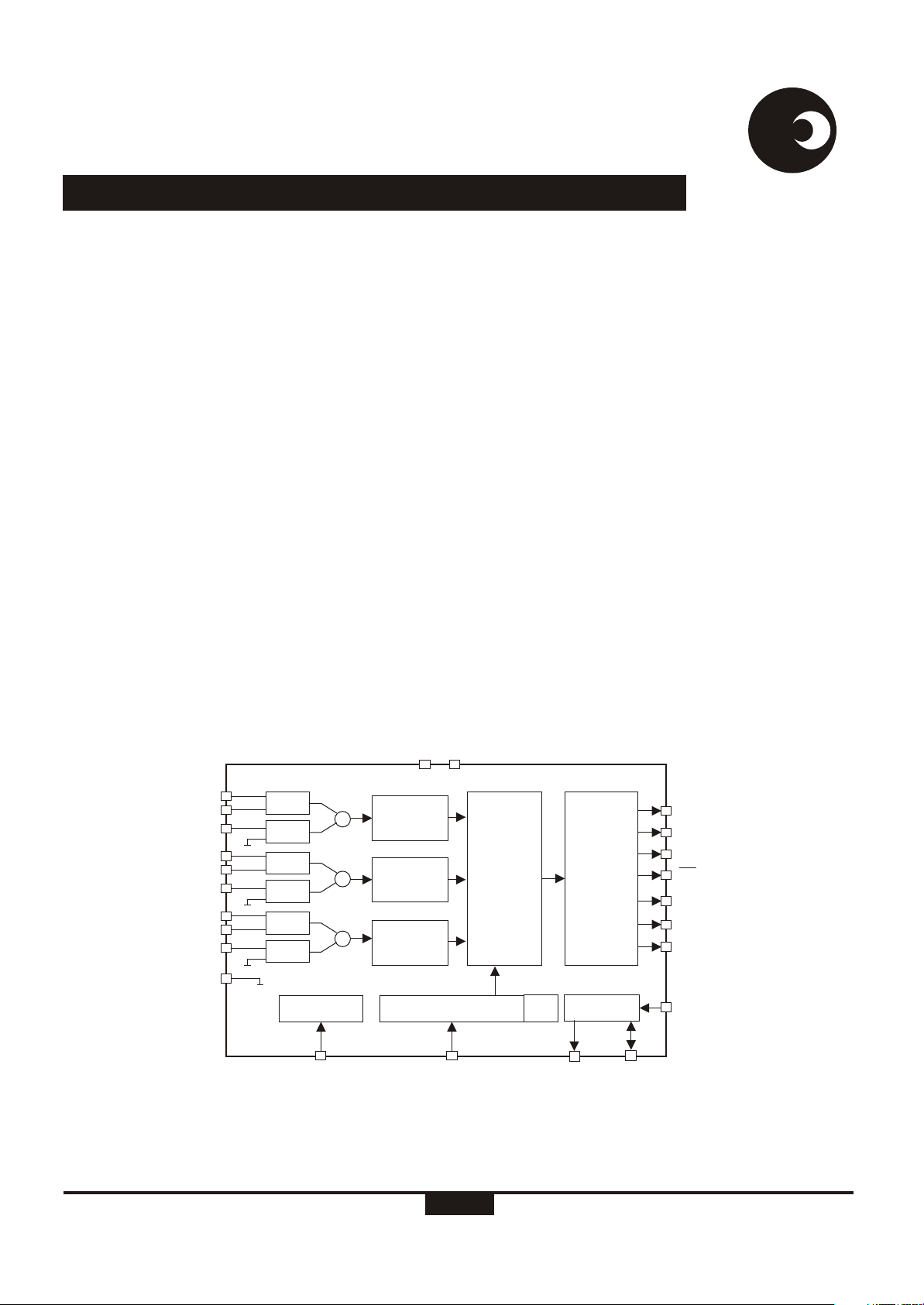
DESCRIPTION
The SAMES SA2005P provides a single chip active energy
metering solution for three phase mechanical counter-based
meter designs.
Th SA2005P does not require any external trim-pots or resistor
ladders for meter calibration. Calibration and meter
configuration information is stored on a small external
EEPROM.
Meter setup stored on the EEPROM includes various metering
direction modes (total sum, absolute sum, positive or negative
energy) phase calibration data, rated metering conditions,
LED pulse rate, counter pulse width, counter resolution and
creep current.
samessames
+ Meets the IEC 521/1036 Specification requirements for
Class 1 AC Watt hour meters
+ Operates over a wide temperature range
+ Easily adaptable to different signal levels
+ Adaptable to different types of sensors
+ Precision voltage reference on-chip
+ Protected against ESD
A programmable rate pulse output is available for meter
calibration purposes. Per phase voltage fail and voltage
sequence faults as well as energy direction indication are
available as LED outputs. Programmable dividers enable
various mechanical counter or stepper motor counter
resolutions.
A precision oscillator, that replaces an external crystal, is
integrated on chip. A voltage reference is integrated on chip.
The SA2005P integrated circuit is available in 24-pin dual in
line plastic (DIP-24) and small outline (SOIC-24) package
options.
IIN1
IIP1
IVN1
IIN2
IIP2
IVN2
IIN3
IIP3
IVN3
GND
dr-01605
I1
V1
I2
V2
I3
V3
REF
VREF
X
X
X
VDD VSS
CHANNEL
BALANCE
PROG.
CHANNEL
ADDER
BALANCE
CHANNEL
BALANCE
TIMING & CONTROL
Figure 1: Block diagram
PROGRAM-
MABLE
ADDER
TEST
OSC
POWER
TO
PULSE
RATE
INTERFACE
SCL
LED
MON
MOP
PH / DIR
PH1
PH2
PH3
RLOAD
SDA
SPEC-0086 (REV. 2)
1/16
07-02-01
Page 2
SA2005P
samessames
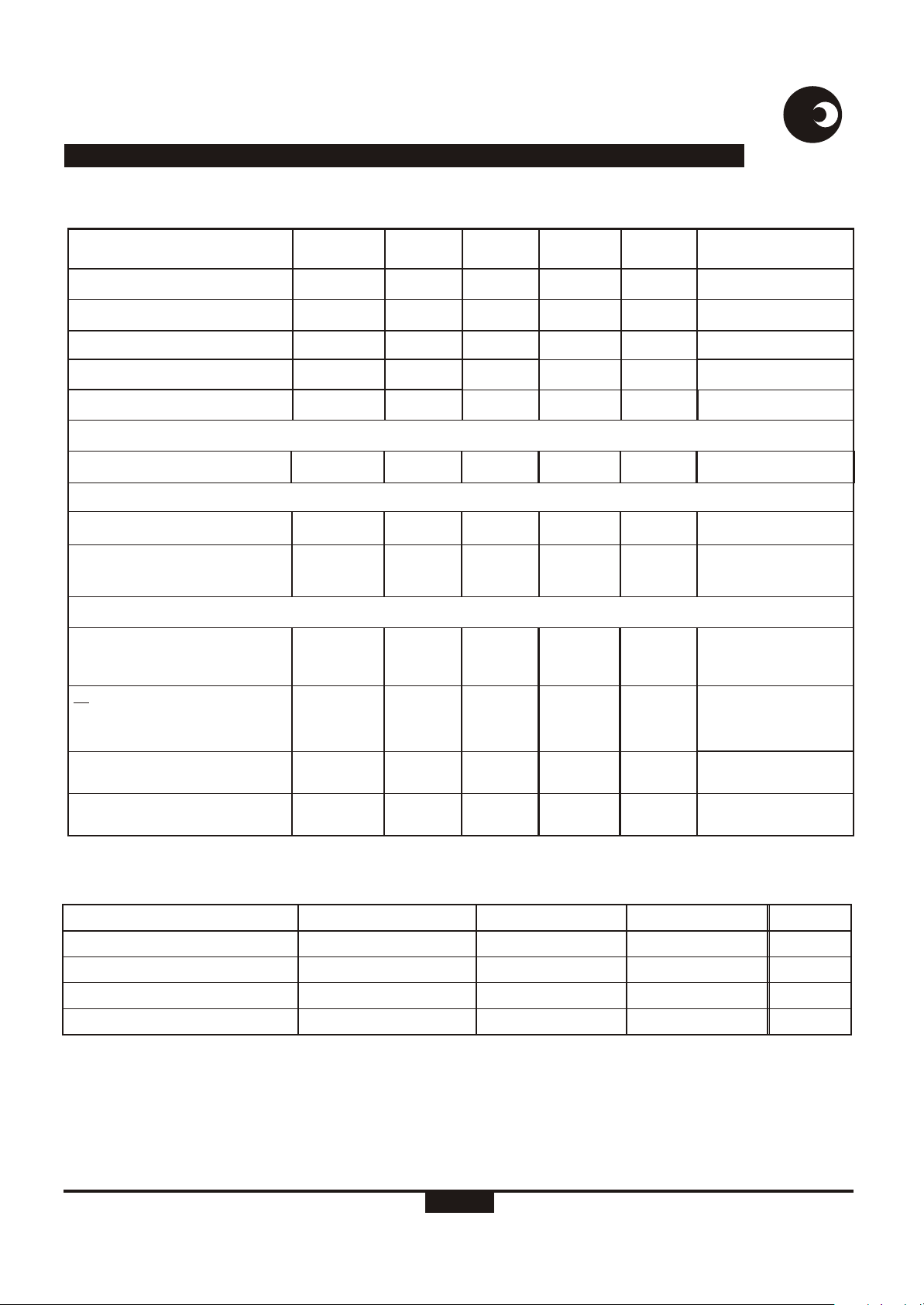
ELECTRICAL CHARACTERISTICS
(V = 2.5V, V = -2.5V, over the temperature range -10°C to +70°C , unless otherwise specified.)
DD SS
Parameter
Operating temp. Range
Supply Voltage: Positive
Supply Voltage: Negative
Supply Current: Positive
Supply Current: Negative
Symbol
T
O
V
DD
V
SS
I
DD
I
SS
Min
-25
2.25
-2.75 -2.25
#
Typ
Max
+85
2.75
15
15
16
16
Current Sensor Inputs (Differential)
Input Current Range
I
II
-25
+25
Voltage Sensor Input (Asymmetrical)
Input Current Range
Pin VREF
Ref. Current
Ref. Voltage
I
IV
-I
R
V
R
-25
45
1.1
50
+25
55
1.3
Digital I/O
Pins RLOAD, TEST, SDA
Input High Voltage
Input Low Voltage
V
IH
V
IL
V-1
DD
V+1
SS
Pins MOP, MON, LED, SCL,
PH/DIR, PH1, PH2, PH3
Output High Voltage
Output Low Voltage
V
OH
V
OL
V-1
DD
V+1
SS
Pin SDA
Pull up current
-I
IL
24
54 µA
Unit
°C
V
V
mA
mA
µA
µA
µA
V
V
V
V
V
Condition
Peak value
Peak value
With R = 24kW
connected to V
Reference to V
I = -2mA
OH
I = 5mA
OL
V = V
ISS
SS
SS
Pins TEST, RLOAD
Pull down current
I
IH
48 110 µA
V = V
IDD
#Extended Operating Temperature Range available on request.
ABSOLUTE MAXIMUM RATINGS*
Parameter Symbol Min Max Unit
Supply Voltage V -V -0.3 6.0 V
Current on any pin I -150 +150 mA
Storage Temperature T -40 +125 °C
Operating Temperature T -40 +85 °C
*Stresses above those listed under “Absolute Maximum Ratings” may cause permanent damage to the device. This is a stress
rating only. Functional operation of the device at these or any other condition above those indicated in the operational sections of
this specification, is not implied. Exposure to Absolute Maximum Ratings for extended periods may affect device reliability.
http://www.sames.co.za
DD SS
PIN
STG
O
2/16
Page 3
SA2005P
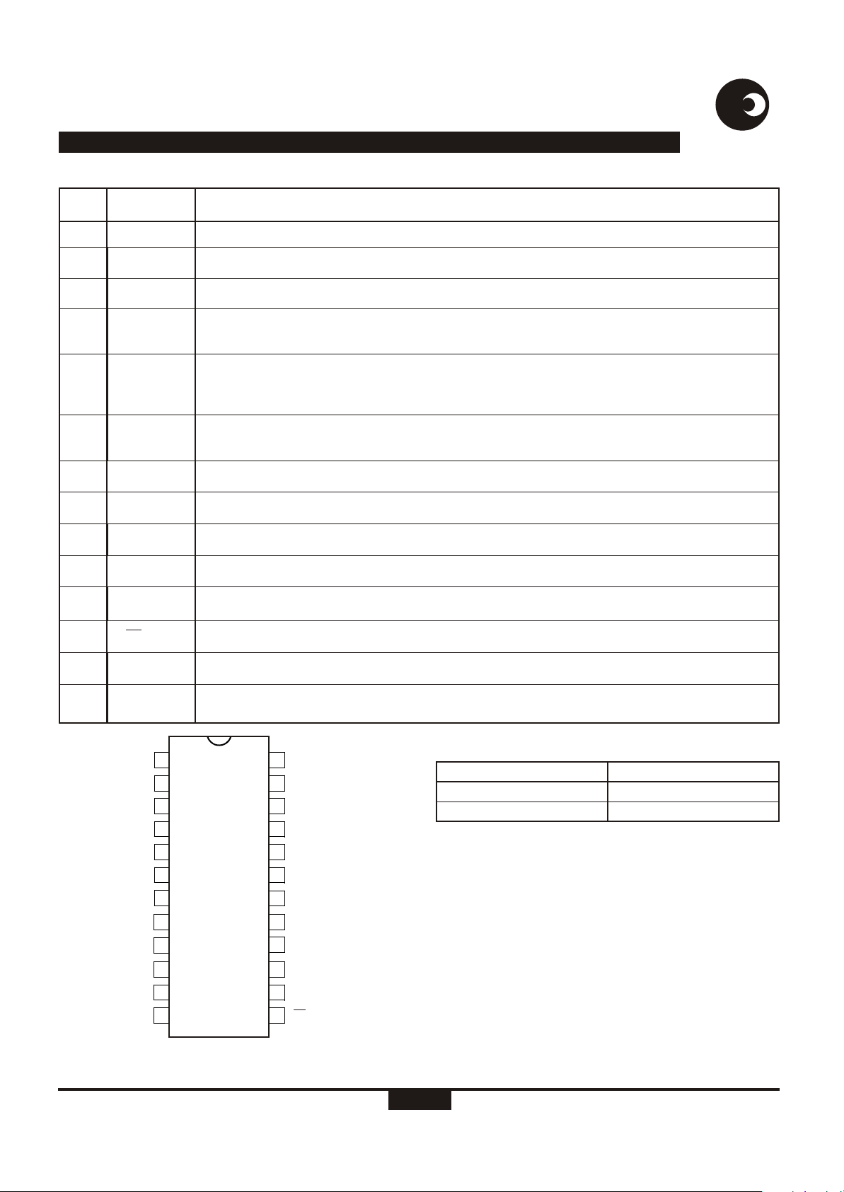
PIN DESCRIPTION
Designation Description
PIN
samessames
20
6
18
21, 24,
3
23, 22,
2, 1,
5, 4
19
8
9
17
10
11, 12
13
GND
V
DD
V
SS
IVN1, IVN2,
IVN3
IIN1, IIP1,
IIN2, IIP2,
IIN3, IIP3
VREF
SCL
SDA
TEST
LED
MON, MOP
PH / DIR
Analog Ground. The voltage to this pin should be mid-way between V and V .
DD SS
Positive supply voltage. Typically +5V if a current transformer is used for current sensing.
Negative supply voltage. Typically 0V if a current transformer is used for current sensing.
Voltage sense inputs. The current into the A/D converter should be set at 14µA at nominal mains
RMS
voltage. The voltage sense input saturates at an input current of ±25µA peak.
Inputs for current sensors. The termination resistor voltage from each current transformer is
converted to a current of 16µA at rated conditions. The current sense input saturates at an input
RMS
current of ±25µA peak.
This pin provides the connection for the reference current setting resistor. A 24kW resistor
connected to V sets the optimum operating condition.
SS
Serial clock output. This output is used to strobe data from the external EEPROM.
Serial data. Send and receive data from an external EEPROM.
Test input. For normal operation connect this pin to V .
SS
Calibration LED output. Refer to section Led Output (LED) for the pulse rate output options.
Motor pulse outputs. These outputs can be used to drive an impulse counter or stepper motor directly.
Multiplexed phase or direction driver output.
7
14, 15,
16
RLOAD
PH1, PH2,
PH3
1IIP2 IVN2
IIN2 IIN1
2
3
IVN3 IIP1
IIP3
4
IIN3
5
VDD
6 19
RLOAD
SCL
SDA
LED
MON
MOP
7
8
9
10
11
12
Triggers a data reload from the external EEPROM.
Multiplexed LED drivers for direction and mains fail indication.
24
23
22
IVN1
21
GND
20
VREF
VSS
18
TEST
17
PH3
16
PH2
15
PH1
14
PH / DIR
13
dr-01602
Figure 2: Pin connections: Package: DIP-24, SOIC-24
ORDERING INFORMATION
Part Number
SA2005PPA
SA2005PSA
Package
DIP-24
SOIC-24
http://www.sames.co.za
3/16
Page 4
SA2005P
FUNCTIONAL DESCRIPTION
The SAMES SA2005P is a CMOS mixed signal analog/digital
integrated circuit that performs three phase power/energy
calculations across a power range of 1000:1 to an overall
accuracy of better than Class 1.
The integrated circuit includes all the required functions for 3phase power and energy measurement such as oversampling
A/D converters for the voltage and current sense inputs, power
calculation and energy integration. Internal offsets are
eliminated through the use of cancellation procedures.
samessames
operation of the meter. Every data byte stored in the EEPROM
is protected with a checksum byte to ensure data integrity.
ELECTROSTATIC DISCHARGE (ESD) PROTECTION
The SA2005P integrated circuit's inputs/outputs are protected
against ESD.
POWER CONSUMPTION
The overall power consumption rating of the SA2005P
integrated circuit is less than 80mW with a 5V supply.
The integrated circuit includes all the required functions for a
three phase mechanical counter-based meter design. A
precision oscillator, that replaces an external crystal, is
integrated on chip providing a temperature stable time base for
the digital circuitry. A temperature stable voltage reference
integrated on chip generates the reference current used by the
analog circuitry.
Voltage and currents are sampled simultaneously by means of
a sigma delta modulator type ADC and power is calculated for
each individual phase. A programmable channel balance on
each channel is used for individual channel calibration.
The scaled power is fed to a programmable adder that allows
the representation of the measured energy to be either total
sum or absolute sum.
The summed power is integrated and divided down to
represent integrated energy. Pulses on the LED output and on
the mechanical counter outputs represent measured amounts
of energy. The programmable dividers provide flexible counter
and calibration LED resolutions.
Outputs for phase voltage fail and voltage sequence faults and
energy direction are available.
The SA2005P does not require any external trim-pots or
resistor ladders as meter calibration and configuration data is
stored on a small external EEPROM. The SA2005P configures
itself from the EEPROM during power up. These features
enables meter manufacturers flexible meter designs from a
single integrated circuit.
AUTOMATIC DEVICE CONFIGURATION (BOOT UP)
During power up, registers containing configuration and
calibration information is updated from an external EEPROM.
The device itself never writes tot he EEPROM so any write
protect features offered by manufacturer of EEPROM’s may
be used to protect the configuration and calibration constant of
the meter. The device reloads its configuration every 1193
seconds from the external EEPROM in order to ensure correct
INPUT SIGNALS
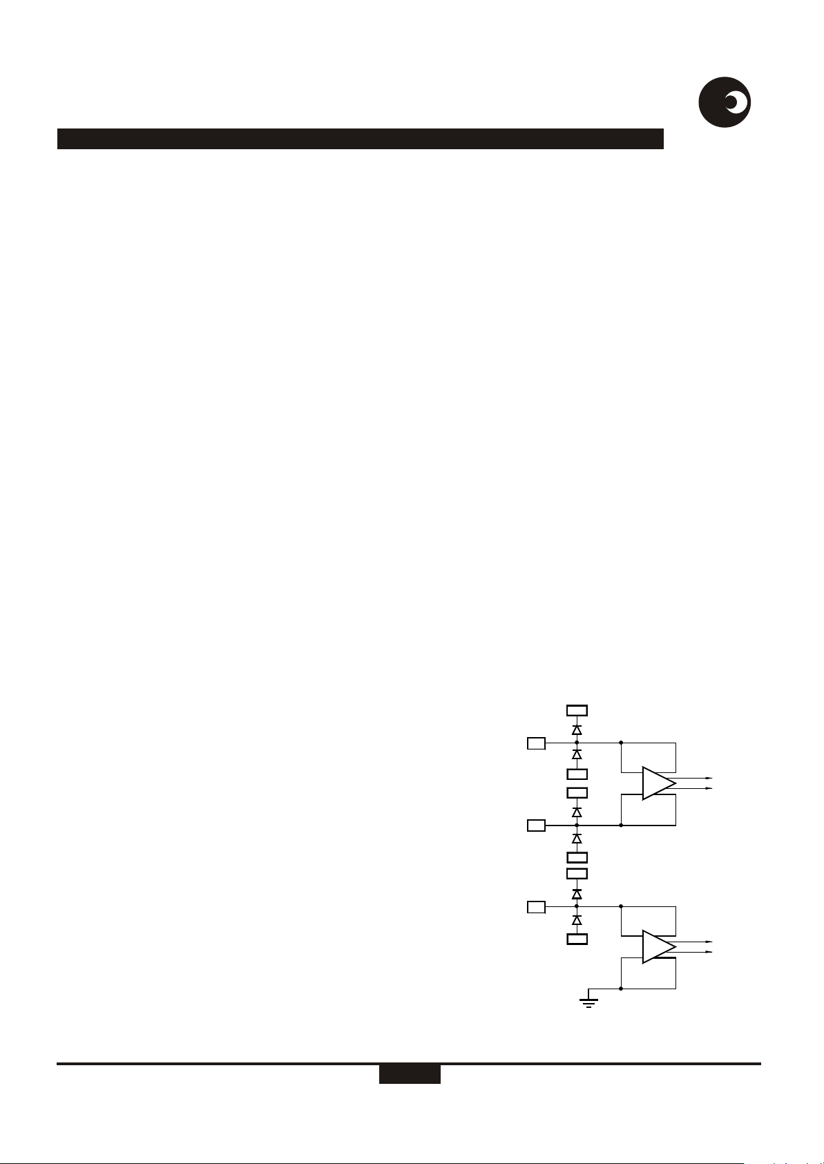
ANALOG INPUT CONFIGURATION
The current and voltage sensor inputs are illustrated in figure 3.
These inputs are protected against electrostatic discharge
through clamping diodes, in conjunction with the amplifiers
input configuration. The feedback loops from the outputs of the
amplifiers A and A generate virtual shorts on the signal inputs.
Exact duplications of the input currents are generated for the
analog processing circuitry. The current and voltage sense
inputs are identical. Both inputs are differential current driven
up to ±25µA peak. One of the voltage sense amplifiers input
terminals is internally connected to GND. This configuration is
possible because the voltage sense input is much less
sensitive to externally induced parasitic signals compared to
the current sense inputs.
Current Sense Inputs (IIN1, IIP1, IIN2, IIP2, IIN3, IIP3)
The current sense inputs connects to a termination resistor
connected across the terminals of a current transformer. At
I V
V
DD
IIP
V
CURRENT
SENSOR
INPUTS
IIN
IVP
VOLTAGE
SENSOR
INPUT
DR-01288
SS
V
DD
V
SS
V
DD
V
SS
GND
A
I
A
V
Figure 3: Analog input internal configuration
http://www.sames.co.za
4/16
Page 5
SA2005P
samessames
rated current the resistor values should be selected for input
currents of 16µA . Referring to figure 8, the resistors R1 and
RMS
R2 on current channel 1, resistors R3 and R4 on current
channel 2 and resistors R5 and R6 on current channel 3, define
the current level into the current sense inputs of the SA2005P.
The current sense inputs saturates at an input current of
±25µA peak. Resistors R29, R30 and R31 are used as current
transformer termination resistors. The voltage drop across the
termination resistors should be at least 20mV at rated
conditions. Values for the current sense inputs are calculated
as follows:
R1 = R2 = ( IL / 16µARMS ) x R29 / 2
R3 = R4 = ( IL / 16µARMS ) x R30 / 2
R5 = R6 = ( IL / 16µARMS ) x R31 / 2
Where:
I = Line current/CT-ratio
L
In case a current transformer is used for current sensing the
value of the termination resistors should be less than the
resistance of the CT's secondary winding.
Voltage Sense Inputs (IVN1, IVN2, IVN3)
The mains voltage are measured by means of a resistor divider
and the divided voltage are converted to a current. The current
into the voltage sense inputs (virtual ground) should be set to
14µARMS at rated voltage conditions. The individual mains
voltages are divided down to 14V per phase. The resistors
RMS
R12, R13 and R14 (figure 8) set the current for the voltage
sense inputs. The voltage sense inputs saturate at an input
current of ±25uA peak.
Voltage Reference Connection (VREF)
A bias resistor of 24k provides an optimum bias conditions on
chip. Calibration of the SA2005P is done by means of divider
ratios stored on an external EEPROM. This is described in the
Device Configuration section.
Serial Data (SDA)
The SDA pin connects directly to the SDA pin of an external
EEPROM. The pin is used to transfer data between the
EEPROM and the SA2005P. An external pull-up resistor in not
needed.
Serial Clock (SCL)
The SCL pin connects directly to the SCL of an external
EEPROM. The SCL output is used to strobe data at a rate of
50kHz out of the EEPROM. An external pull up resistor is not
needed. The SCL output uses a soft driver and may be
overdriven by the calibration equipment.
Reload (RLOAD)
A falling edge on the RLOAD pin will trigger a register update
from the external EEPROM. This feature may be used during
calibration to load updated register data in the SA2005P. For
normal operation of the SA2005P the RLOAD pin may be left
floating.
Test Inputs (TEST)
The TEST input is the manufacturers test pin and must be
connected to VSS in a metering application.
OUTPUT SIGNALS
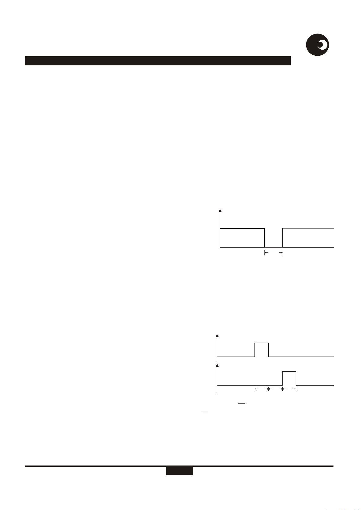
LED Output (LED)
Four options for the LED output pulse rate are available, 6400,
3200, 1600 pulses per kWh, and a pulse rate of 1252 pulses
per second at rated conditions. At 1252 pulses per second t LED
is 71µs, for the other options tLED is 10ms. The LED output is
active low as shown in figure 4.
VDD
LED
VSS
DR-01332
Figure 4: LED pulse output
Motor Output (MOP, MON)
The motor pulse width is programmable for 71ms, 142ms and
284ms. The MON pulse will follow the MOP pulse within the
selected pulse width time. This prevents the motor armature
being in the wrong position after a power failure. Both MOP
and MON outputs are active high. A MOP pulse followed by a
MON pulse represents one energy pulse. The motor drive
waveforms are shown in figure 5.
VDD
MOP
VSS
VDD
MON
VSS
DR-01559
Figure 5: Motor drive on MON and MOP pins of device
Multiplex Output (PH/ DIR)
The PH/DIR output enables either direction or voltage
information on the phase LED driver outputs (PH1, PH2 and
PH3). This multiplex output switches between logic 1 and 0 at
a frequency of approximately 280Hz. A logic 1 enables energy
direction information on the LED driver outputs and a logic 0
enables voltage information.
t
LED
t
m
t
t
m
m
http://www.sames.co.za
5/16
Page 6

SA2005P
samessames
The PH/Dir output is used in conjunction with the LED driver
outputs to display information about each individual phase, see
figure 6.
Phase LED Drivers (PH1, PH2, PH3)
The LED driver outputs present either direction information or
voltage information. The three LED driver outputs are used in
conjunction with the PH/DIR output to display information
about each individual phase (refer to figure 6) as follows:
PH/DIR = 1 (Direction indication)
When PH/DIR is high (logic 1) energy direction information for
each individual phase is available on PH1, PH2 and PH3. A
logic 0 indicates reverse energy flow and a logic 1 indicates
positive energy flow. Reverse energy flow is defined as the
condition where the voltage sense input and the current sense
inputs are out of phase (greater than 90 degrees). Positive
energy flow is defined as the condition where the voltage
sense and current sense inputs are in phase.
PH/DIR = 0 (Voltage fail / phase sequence error)
When PH/DIR is low (logic 0) voltage information is available
on PH1, PH2 and PH3. A logic 0 on any of these pins indicates
a voltage failure, the SA2005P does not detect a zero crossing
on the applicable voltage sense input. Referring to figure 6 the
voltage fail LED will be on when the voltage phase is present
and off when the voltage phase is missing.
In the case of a phase sequence error all three LED driver
outputs PH1, PH2 and PH3 will pulse with a repetition rate of
approximately 1Hz.
Channel 1
Channel 2
Channel 3
PH (Sink)
DIR (Drive)
VFAIL 1
DIR 1
VFAIL 2
DIR 2
VFAIL 3
DIR 3
dr-01603
PH/DIR
R9
PH1
R10
PH2
R11
PH3
D1
DIR1
D2
VFAIL1
Figure 6: Multiplexing of the LED Drivers
D3
DIR2D4VFAIL2
D5
DIR3
D6
VFAIL3
http://www.sames.co.za
6/16
Page 7

SA2005P
ANTI-TAMPER CONDITIONS
The SA2005P cater for the following meter tamper conditions and are indicated as follows:
samessames
Method Result
Phase
Voltages
Phase Failure,
no voltage
Phase
Sequence
Error
Input / Output
Terminals
Interchanged
Missing
Neutral
Connection
Return
through Earth
Load
Imbalance
Calibration
One LED is provided for each phase to indicate abnormal
operating conditions.
In case of a phase failure, the corresponding LED is
switched off.
In case of phase sequence error, all LEDs are flashing with a repetition rate of approximately 1 Hz. A connection of a line voltage
to the neutral terminal would be indicated in the same way.
One LED is provided for each current sensor to indicate reverse
energy flow. If detected, the corresponding LED is switched on.
The SA2005P can be configured to accumulate the absolute
energy consumption for each phase measured, irrespective of
the direction of the energy flow.
The architecture of the meter should provide for a good "phantom
neutral" in cases where the neutral is disconnected from the
meter.
The SA2005P will therefore record the energy consumption
accurately under this condition.
The calibration data is stored in an EEPROM. There are no
trim-pots required in this design.
Description
During normal conditions, the LEDs
are continuously switched on.
The SA2005P will record the energy
consumption accurately under this condition
The SA2005P will record the energy
consumption accurately under this condition
The SA2005P will record the energy
consumption accurately under this condition
In this case, the meter would register the
energy consumption correct.
A indication for this condition could be
realized external to the IC.
The SA2005P will record the energy
consumption accurately under this condition
The meter can not be re-adjusted, only
reprogrammed.
http://www.sames.co.za
7/16
Page 8

SA2005P
samessames
DEVICE CONFIGURATION
SIGNAL FLOW DESCRIPTION
The following is an overview of the SA2005P’s registers. For a
detailed description of each parameter please refer to
parameter description section. Figure 7 shows the various
registers in the SA2005P’s power to pulse rate block. The
inputs to this block are three single bit pulse density modulated
signals, each having a pulse rate of 641454 pulses per second
at rated conditions. The parameters Cb1, Cb2, Cb3, Sum, Ct,
Kr, CresH, CresL, Cled and Pw contain values that are read
from the external EEPROM during power up.
The Pre-Divider registers are used for calibration and to
balance the gain of each channel. The Programmable Adder is
used to select between the total sum or absolute sum of the
measured energy. The Creep current threshold detector
selects the creep current which is relative to the meters rated
current. The Rated Condition register is used to program the
rated condition of the meter and feeds the registers LED-
constant and Counter Resolution with the applicable pulse
rate. These two registers are programmed to select the LED
output rate and the counter resolution (pulses per kWh)
respectively. The Counter Pulse Width register is used to
program the pulse width for the mechanical counter driver
output MOP and MON.
EEPROM Memory Allocation
The following table shows the EEPROM memory allocation as
well as the corresponding name. The uneven byte always
Power from converters
S - D Power from converters
641454 pulses/s
Pre-Divider
÷Cb1
Creep current threshold detector
Rated Condition
÷Kr
Counter
Resolution
CresH, CresL
Counter Pulse
width
Pw
MOP MON
Ct
S - D Power from converters
641454 pulses/s
Pre-Divider
÷Cb2
Programmable Adder SUM
Normally 1253p/s
Normally 6400p/kWh
S - D
641454 pulses/s
Pre-Divider
÷Cb3
LED-Constant
Cled
LED
Figure 7: Signal flow block diagram
contains a XORed byte of the previous even byte. This is the
checksum byte used by the SA2005P to ensure data integrity.
Description
Channel Balance 3
Channel Balance 1
Channel Balance 2
Summing mode
Creep current threshold
Rated Condition
Led Pulse-rate
Counter Resolution (LSB)
Counter Resolution (MSB)
Counter Pulse-Width
2
E Address
10
11
12
13
14
15
16
16
17
20
21
22
23
24
25
26
26
27
Contents
Cb3
XOR of ADDR 10
Cb1
XOR of ADDR 12
Cb2
XOR of ADDR 14
SUM
Ct
XOR of ADDR 16
Kr
XOR of ADDR 20
Cled
XOR of ADDR 22
CresL
XOR of ADDR 24
ClresH
Pw
XOR of ADDR 26
---v vvvv
xxxx xxxx
---v vvvv
xxxx xxxx
---v vvvv
xxxx xxxx
---- --vv
v--- ----
xxxx xxxx
vvvv vvvv
xxxx xxxx
---- --vv
xxxx xxxx
vvvv vvvv
xxxx xxxx
---v vvvv
vv-- ----
xxxx xxxx
KEY: (- = DON’T CARE); (V = VALUE/PARAMETER); (0,1 = LOGICAL VALUE); (X = BIT-XOR)
Bit [7:0]
Name
D10
D12
D13
D16
D16
D20
D22
D24
D26
D26
http://www.sames.co.za
8/16
Page 9

SA2005P
samessames
PARAMETER DESCRIPTION
Refer to the EEPROM memory allocation map as well as the
Signal flow diagram figure 7, for a description of the registers
used in this section.
Rated Condition (Kr)
Kr is used to program the rated condition of the meter. Rated
conditions from less than 10A to several 100A are possible.
The rated conditions divider as well as the pre-divider is used
to compensate for individual phase calibration. The three
phases are calibrated to the phase with the lowest gain.
Kr is calculated as follows:
Krx=642 000/Rated volt/Rated current/6400x3600x1000/512
The SA2005P’s internal counters count from 0 so 1 must be
subtracted from Kr:
Kr = round(Krx)-1
Where:
Krx is the real value
Kr is the integer value
Kr is made up of 1 byte (D20)
LED Pulse-Rate (Cled)
Two bits of byte D22 allow for the selection of 4 different LEDPulse-rates. The LED pulse-width is 10ms. In fast pulse mode,
the pulse-width is set to 71µs.
D22[1]
0
1
1
0
Counter Resolution (Cres)
A 13 bit divider divide the pulse rate from the rated conditions
divider down to the desired counter resolution.
Cres is made up of bits 0 of 4 of byte D26 and byte D27.
D26[4:0] D27[7:0]
Counter Pulse-Width (Pw)
The pulse width for the mechanical counter driver output is
selectable to accommodate various step-motor and impulsecounter requirements.
D22[0]
1
0
1
0
Calibration LED - Output
6400 p/kWh
3200 p/kWh
1600 p/kWh
1252 pulses/second @ rated for
fast calibration
Counter Resolution
Pre-divider (Cb1, Cb2, Cb3)
The channel balance (Cb) value is used to balance the three
phases. The rated conditions divider ratio must be calculated.
Error measurements per phase are done with channel balance
values set to zero. The measured error values are used to
correct the error measurements of the three phases. The
rounding error in the rated conditions divider is also
compensated for in the channel balance calculations. One
count on the channel balance value represent 100%/256.
Gain = ((Krx-Kr+1) / Krx) x 100
Gain calculates the rounding error made by the rated
conditions divider.
Cb1 = (CHB1 - CBMIN + Gain) x 256 / 100
Cb2 = (CHB2 - CBMIN + Gain) x 256 / 100
Cb3 = (CHB3 - CBMIN + Gain) x 256 / 100
CHB1, CHB2, CHB3 is the measured channel balance %error
that will be corrected
CBMIN is the lowest channel balance %error measured
between the three phases.
Pw is made up of bits 7 and 6 of byte D26.
D26[7]
1
0
0
Creep current threshold (Ct)
The creep current is expressed relative to the rated current of
the meter. The SA2005P will not meter currents below the
creep current. The creep current is implemented to prevent
the meter from accumulating energy when no load is
connected.
Cs is made up of bit 7 of byte D16
D16[7]
0
1
D26[6]
-
1
0
Creep threshold
0.02% of rated current
0.01% of rated current
Counter Pulse-Width
284 ms
142 ms
71 ms
http://www.sames.co.za
9/16
Page 10

SA2005P
Programmable adder mode (SUM)
The SA2005P can be programmed to sum the energy
measurement as follows:
Total sum
This represents the total sum of the energy measured on all
three phases flowing through the current sensors. Negative
energy flow is taken into consideration.
Energy = Energy phase 1 + Energy Phase 2 + Energy
Phase 3
Absolute sum
This represents the sum of the energy measured on all three
phases, regardless of the direction of energy flow through
the current sensors.
Power = abs (Energy phase 1) + abs (Energy phase 2) +
abs (Energy phase 3)
During calibration the device may be programmed to use only
a specific phase for energy measurement. This can be used for
channel balancing.
D16[2]
Example of calculating rated conditions and channel
balance values
Meter rating = 80A / 230V (The SA2005P only uses integer
values)
D16[1]
0
0
0
0
1
1
1
1
D16[0]
0
0
1
1
0
0
1
1
Counter Resolution
Total sum all three phases
0
Only phase 1 measurement
1
Only phase 2 measurement
0
Only phase 3 measurement
1
Absolute sum of all three phases
0
Only phase 1 measurement
1
Only phase 2 measurement
0
Only phase 3 measurement
1
samessames
Calculate the Channel balance values:
During the rated conditions calculation the rated condition
register was rounded and any rounding errors is now taken
into account:
Gain = ((Krx - Kr+1 ) / Krx) x 100
Gain = ((38.3327 - 38) / 38.337) x 100
Gain = 0.8679
The real channel balance errors still need to be measured so
CHB1,CHB2, CHB3 and CBMIN are set to 0 for all phases.
Calculate the Pre-divider values:
Cb1 = (CHB1 - CBMIN + Gain ) x 256 / 100
Cb1 = (0% - 0% + Gain ) x 256 / 100
Cb1 = Gain x 256 / 100
Cb1 = 0.8679 x 256 / 100
Cb1 =2.2218
Convert to integer
Cb1 = 2
At this stage all three channels will be set with the same
values, Cb1= Cb2= Cb3. Store the calculated values in the
EEPROM. Ensure that the SA2005P reload’s its registers from
the EEPROM by means of the reload pin (RLOAD) or power
down the meter and power up again.
The meter is now set up with the correct register values but not
yet calibrated.
The following example shows how to calibrate the meter
Use the rated conditions divider value and the channel
balance values calculated above and program the EEPROM.
Set the programmable adder for a single phase to be
measured. Measure the %error for each individual phase
without changing any of the calibration constants.
%Error=(Measured Energy-Real Energy)/Real Energyx100
Calculate the rated conditions:
Krx=642 000/Rated volt/Rated current/6400x3600x1000/512
Krx = 642 000/230/80/6400x3600x1000/512
Krx = 38.3327
Krx = 38 (round Krx) - convert to integer
Kr = 38 - 1 = 37
The value 37 is stored in the rated register (Kr).
http://www.sames.co.za
The %Error will be worked back into the calculations above.
For the example we will assume a 1.5%, 5.2%, and 3.2% for
the three individual phases. The rated conditions value is
recalculated relative to the phase with the lowest error. Phase
1 has the lowest error so 1.5% = MinError;
10/16
Page 11

SA2005P
Recalculate the rated conditions
Krx = 642 000 / Rated volt / Rated current / 6400 x 3600 x
1000 / 512 x (1 + %MinError / 100 )
Krx = 642 000 / 230 / 80 / 6400 x 3600 x 1000 / 512 x 1.015
Krx = 38.9077
Kr = 38 - 1 = 37
The 37 are stored in the rated register.
The channel balance values are adjusted to make provision for
the rounding error.
Gain = ((Krx - Kr +1 ) / Krx ) x 100
Gain = (( 38.9077 - 38 ) / 38.9077 ) x 100
Gain = 2.33
The channel balance pre-devider value must be recalculated.
(BMIN will be the lowest %error value, in this case 1.5%,
CHB1, CHB2 and CHB3 are the individual phase %errors
measured.
samessames
Cb1 = (CHB1 - CBMIN + Gain ) x 256 / 100
Cb1 = (1.5 - 1.5 + 2.33 ) x 256 / 100 = 5.97 =5
Cb2 = (CHB2 - CBMIN + Gain ) x 256 / 100
Cb2 = ( 5.2 - 1.5 + 2.33 ) x 256 / 100 = 15.43 = 15
Cb3 = (CHB3 - CBMIN + Gain ) x 256 / 100
Cb3 = (3.2 - 1.5 + 2.33 ) x 256 / 100 = 10.316 = 10
Store the calculated values in the EEPROM and the meter is
calibrated.
http://www.sames.co.za
11/16
Page 12

SA2005P
TYPICAL APPLICATION
CALCULATION OF EXTERNAL RESISTOR VALUES
In figure 8, all the components required for a three-phase
power/energy metering section, is shown. The application
uses current transformers for current sensing. The 4-wire
meter section is capable of measuring 3x230V/80A with
precision better than Class 1
The most important external components for the SA2005P
integrated circuit are the current sense resistors, the voltage
sense resistors as well as the bias setting resistor.
samessames
Voltage Divider
The three voltage divider for voltage measurement are
identical so resistor values for one phase will be calculated.
The voltage divider is calculated for a voltage drop of 14V.
Equations for the voltage divider in figure 5 are:
RA = R16 + R19 + R22
RB = R8 || R13
Combining the two equations gives:
Bias Resistor
R7 defines all on-chip and reference currents. With R7=24kW,
optimum conditions are set.
CT Termination Resistor
The voltage drop across the CT termination resistor at rated
current should be at least 20mV. The CT's used have low
phase shift and a ratio of 1:2500.The CT is terminated with a
2.7W resistor giving a voltage drop across the termination
resistor 864mV at rated conditions (Imax for the meter).
Current Sense Resistors
The resistors R1 and R2 define the current level into the
current sense inputs of phase one of the device. The resistor
values are selected for an input current of 16µA on the current
inputs at rated conditions.
According to equation described in the Current Sense inputs
section:
R1 = R2 = ( I / 16µA ) x R / 2
= 80A /2500 / 16µA x 2.7W / 2
= 2.7kW
I = Line current / CT Ratio
L
LSH
(RA + RB ) / 230V = RB / 14V
Resistor values R11 = R12 = R13= 24kW and R8 =1MW is
chosen.
Substituting the values result in:
RB = 23.4375kW
RA = RB x (230V / 14V - 1)
RA = 361.607kW.
Resistor values of R16, R19 and R22 is chosen to be 130k,
130k and 100k.
The three voltage channels are identical so R14= R15= R16 ,
R17 = R18 = R19 and R20 = R21= R22.
The three current channels are identical so R1 = R2 = R3 = R4
= R5 = R6.
http://www.sames.co.za
12/16
Page 13

http://www.sames.co.za
Neutral
V3 In
GND
R18
R21
SA2005P
R24
R16
13/16
V2 In
V1In
CT1
Figure 8: Typical application circuit
CT2
CT3
V3 Out
V2 Out
V1 Out
VSS
1
2
3
4
U2
24C01A
A0
A1
A2
VSS
VCC
TEST
SCL
SDA
R19
R20
GND
GND
GND
8
7
6
5
R29
R30
R31
VDD
VSS
R22
R23
R1
R2
R3
R4
R5
R6
R7
23
22
19
18
17
2
1
5
4
8
9
R25
R26
U1
IIN1
IIP1
IIN2
IIP2
IIN3
IIP3
VREF
VSS
TEST
SCL
SDA
dr-01604
GND
IVN1
IVN2
IVN3
PH/DIR
PH1
PH2
PH3
MOP
MON
LED
VDD
RLOAD
R15
RELOAD
SDA
SCL
R17
D1
DIR1
R8
C5
C4
C3
D2
VFAIL1
VDD
CNT1
.1123456
Counter
D3
DIR2
D4
VFAIL2
GND
R27
R28
D5
DIR3
D6
VFAIL3
VDD
C2
C1
C6
VSS
samessames
20
GND
R12
21
R13
24
R14
3
13
R9
14
R10
15
R11
16
12
11
10
6
7
D7
Page 14

SA2005P
samessames
Parts List for Application Circuit: Figure 7
Symbol
U1
R1
R2
R3
R4
R5
R6
R7
R8
R9
R10
R11
R12
R13
R14
R15
R16
R17
R18
R19
R20
R21
R22
R23
R24
R25
R26
R27
R28
R29
R30
R31
C1
C2
C3
C4
C5
C6
D1
D2
D3
D4
D5
D6
U2
CNT1
CT1
CT2
CT3
Note 1: Resistor (R1 to R6) values are dependent on the selection of the termination resistors (R29 to R31) and CT combination
Note 2: Capacitor values may be selected to compensate for phase errors caused by the current transformers.
Note 3: Capacitor C6 to be positioned as close as possible to supply pins V and V of U1 as possible.
Description
SA2005P
Resistor, 2.7k, 1/4W, 1%, metal
Resistor, 2.7k, 1/4W, 1%, metal
Resistor, 2.7k, 1/4W, 1%, metal
Resistor, 2.7k, 1/4W, 1%, metal
Resistor, 2.7k, 1/4W, 1%, metal
Resistor, 2.7k, 1/4W, 1%, metal
Resistor, 24k, 1/4W, 1%, metal
Resistor, 1k, 1/4W, 5%, carbon
Resistor, 1k, 1/4W, 5%, carbon
Resistor, 1k, 1/4W, 5%, carbon
Resistor, 1k, 1/4W, 5%, carbon
Resistor, 1M, 1/4W, 1%, metal
Resistor, 1M, 1/4W, 1%, metal
Resistor, 1M, 1/4W, 1%, metal
Resistor, 24k, 1/4W, 1%, metal
Resistor, 24k, 1/4W, 1%, metal
Resistor, 24k, 1/4W, 1%, metal
Resistor, 130k, 1/4W, 1%, metal
Resistor, 130k, 1/4W, 1%, metal
Resistor, 130k, 1/4W, 1%, metal
Resistor, 130k, 1/4W, 1%, metal
Resistor, 130k, 1/4W, 1%, metal
Resistor, 130k, 1/4W, 1%, metal
Resistor, 100k, 1/4W, 1%, metal
Resistor, 100k, 1/4W, 1%, metal
Resistor, 100k, 1/4W, 1%, metal
Resistor, 1k, 1/4W, 1%, metal
Resistor, 1k, 1/4W, 1%, metal
Resistor, 2.7 , 1/4W, 1%, metal
Resistor, 2.7 , 1/4W, 1%, metal
Resistor, 2.7 , 1/4W, 1%, metal
Capacitor, 220nF
Capacitor, 220nF
Capacitor, 1.5µF, 16V, electrolytic
Capacitor, 1.5µF, 16V, electrolytic
Capacitor, 1.5µF, 16V, electrolytic
Capacitor, 820nF
3mm Light emitting diode
3mm Light emitting diode
3mm Light emitting diode
3mm Light emitting diode
3mm Light emitting diode
3mm Light emitting diode
24C01A, 1kbit EEPROM
Mechanical stepper motor counter
Current Transformer, TZ76
Current Transformer, TZ76
Current Transformer, TZ76
W
W
W
Detail
DIP-24 / SOIC-24
Note 1
Note 1
Note 1
Note 1
Note 1
Note 1
Note 1
Note 1
Note 1
Note 2
Note 2
Note 2
Note 3
Direction indicator
V1 Fail indicator
Direction indicator
V2 Fail indicator
Direction indicator
V3 Fail indicator
2500:1
2500:1
2500:1
DD SS
http://www.sames.co.za
14/16
Page 15

PM9607AP
SA2005P
samessames
samessames
http://www.sames.co.za
15/16
Page 16

PM9607AP
SA2005P
samessames
samessames
DISCLAIMER:
The information contained in this document is confidential and proprietary to South African Micro-Electronic Systems (Pty) Ltd
("SAMES") and may not be copied or disclosed to a third party, in whole or in part, without the express written consent of SAMES.
The information contained herein is current as of the date of publication; however, delivery of this document shall not under any
circumstances create any implication that the information contained herein is correct as of any time subsequent to such date.
SAMES does not undertake to inform any recipient of this document of any changes in the information contained herein, and
SAMES expressly reserves the right to make changes in such information, without notification, even if such changes would render
information contained herein inaccurate or incomplete. SAMES makes no representation or warranty that any circuit designed by
reference to the information contained herein, will function without errors and as intended by the designer.
Any sales or technical questions may be posted to our e-mail address below:
For the latest updates on datasheets, please visit our web site:
SOUTH AFRICAN MICRO-ELECTRONIC SYSTEMS
DIVISION OF LABAT TECHNOLOGIES (PTY) LTD
P O BOX 15888
33 ELAND STREET
LYNN EAST 0039
REPUBLIC OF SOUTH AFRICA
energy@sames.co.za
http://www.sames.co.za.
Tel : (012) 333-6021
Tel: Int +27 12 333-6021
Fax: (012) 333-8071
Fax: Int +27 12 333-8071
33 ELAND STREET
KOEDOESPOORT INDUSTRIAL AREA
PRETORIA
REPUBLIC OF SOUTH AFRICA
http://www.sames.co.za
16/16
 Loading...