

Page 1
查询RCM1990U-A供应商
RCM1990U-A
Liquid crystal displays
16×16 dots large-sized
liquid crystal display unit
RCM1990U-A
Thanks to the high contrast and wide viewing angle of the RCM1990U-A, which is provided by its unique design
technology, this module brings forth new applications in brand new LCD fields. ROHM large-sized LCD units are perfect
displays for information or sign boards. As a media for informational display, large-sized LCD units must possess high
visibility, wide viewing angles, and other such superior qualities. ROHM large-sized LCDs boast an excellent track record
and possess guaranteed functionality for assured satisfaction in a variety of situations.
zApplica tions
Public displays such as airport displays, train station displays, information boards, and billboards.
zFeatures
1) Wide viewing angle, high contrast, and fast response.
2) Compact and light weight for easy assembly.
3) Low power consumption.
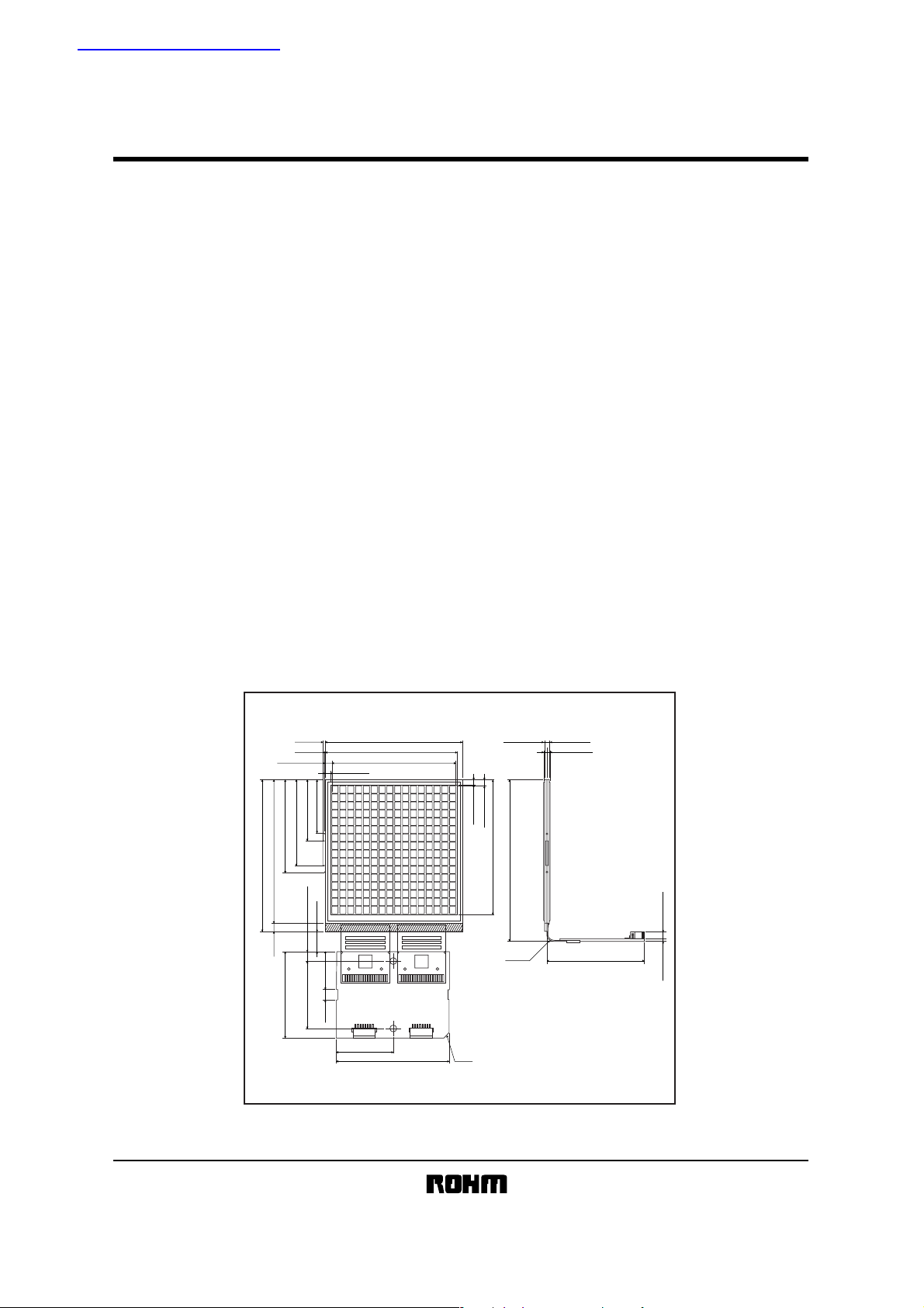
zExternal dimensions (Unit : mm)
1.10
±0.101.10±0.1056.00±0.301.0Max.
2.65±0.30
(40.5)(R3.20)
1.00±0.30 2.70±0.50
61.00±0.30
57.50±0.30(3.50)
36.75Min.35.00±0.50
23.75Min.
33.75Min.
(8.00)
4.00±0.3027.00±0.30
2.00Max.
20.75Min.
(15.00)
(4.00)
81 81
CN 2
±0.30
23.00
54.00Min.0.3Max.
50.97
±0.302.515±0.30
CN 1
46.00±0.50 C2.0
2.00Max.
2.50±0.30
54.00Min.
(64.70)
1/8
Page 2
Liquid crystal displays
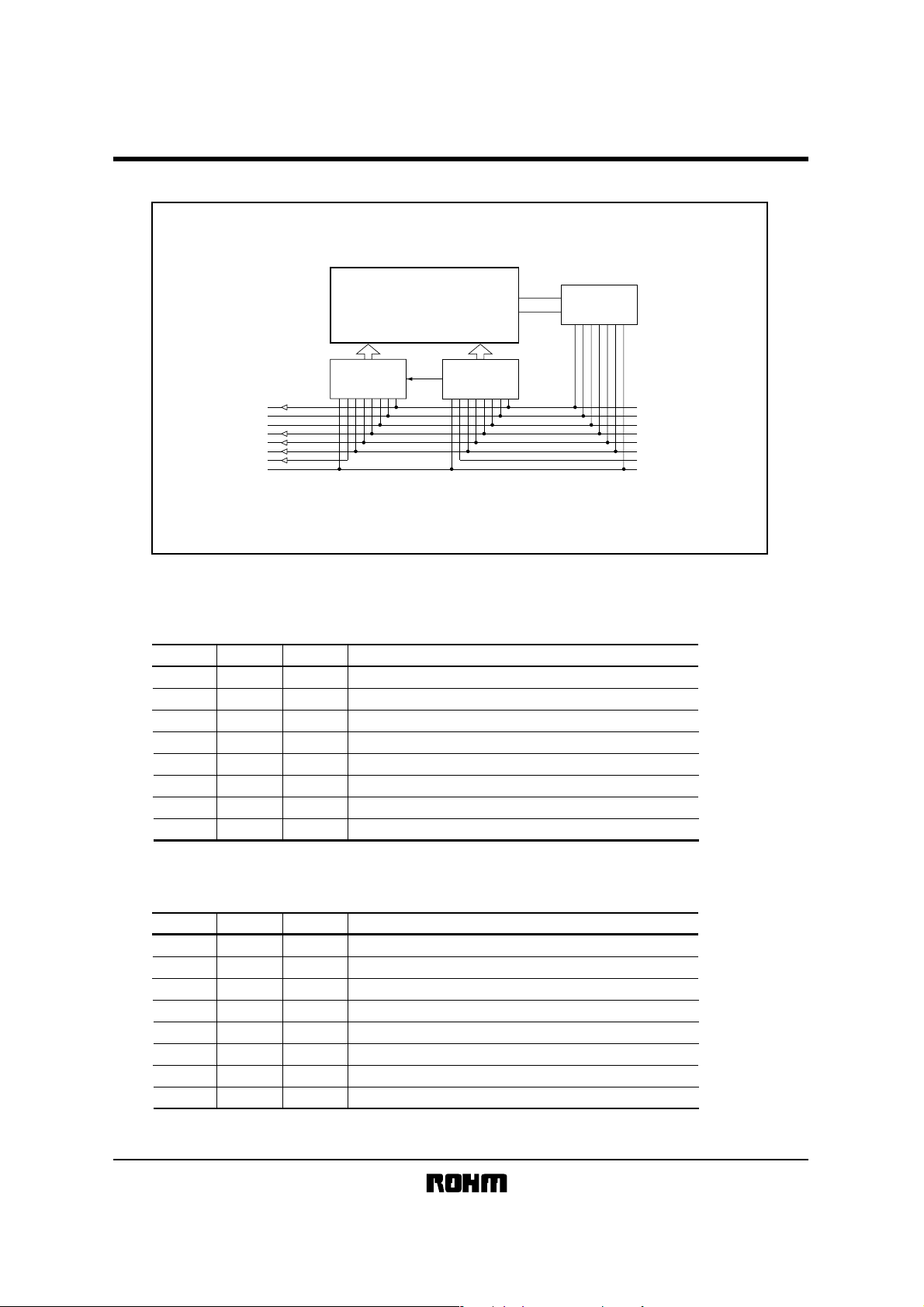
zBlock diagram
RCM1990U-A
zPin functions
Upper board
Input (CN3)
Pin No.
1
2
3
4
5
6
7
8
Output (CN4)
FLM
VO
DD
V
M
CL1
CL2
D
O
GND
OUTPUT
Symbol
FLM
VO
V
DD
M
CL1
CL2
DI
GND
IN/OUT
IN
−
−
IN
IN
IN
IN
−
64 output
driver IC
LCD
64 output
driver IC
COM.2
COM.1
COM
Generator circuit
Function
Frame start signal
Liquid crystal drive power supply
5 volts
AC conversion signal for liquid crystal drive output
Data latch signal, displays at rise / fall edge
Shift register shift signal, reads data at rise / fall
Display data signal (1 : On, 0 : Off)
Ground potential
FLM
VO
DD
V
M
CL1
CL2
DI
GND
INPUT
Pin No.
Symbol
1
2
3
4
5
6
7
8
FLM
VO
V
M
CL1
CL2
DI
GND
IN/OUT
OUT
DD
OUT
OUT
OUT
OUT
Frame start signal
Liquid crystal drive power supply
−
5 Volts
−
AC conversion signal
Data latch signal
Shift register shift signal
Display data signal
Ground potential
−
Function
2/8
Page 3
Liquid crystal displays
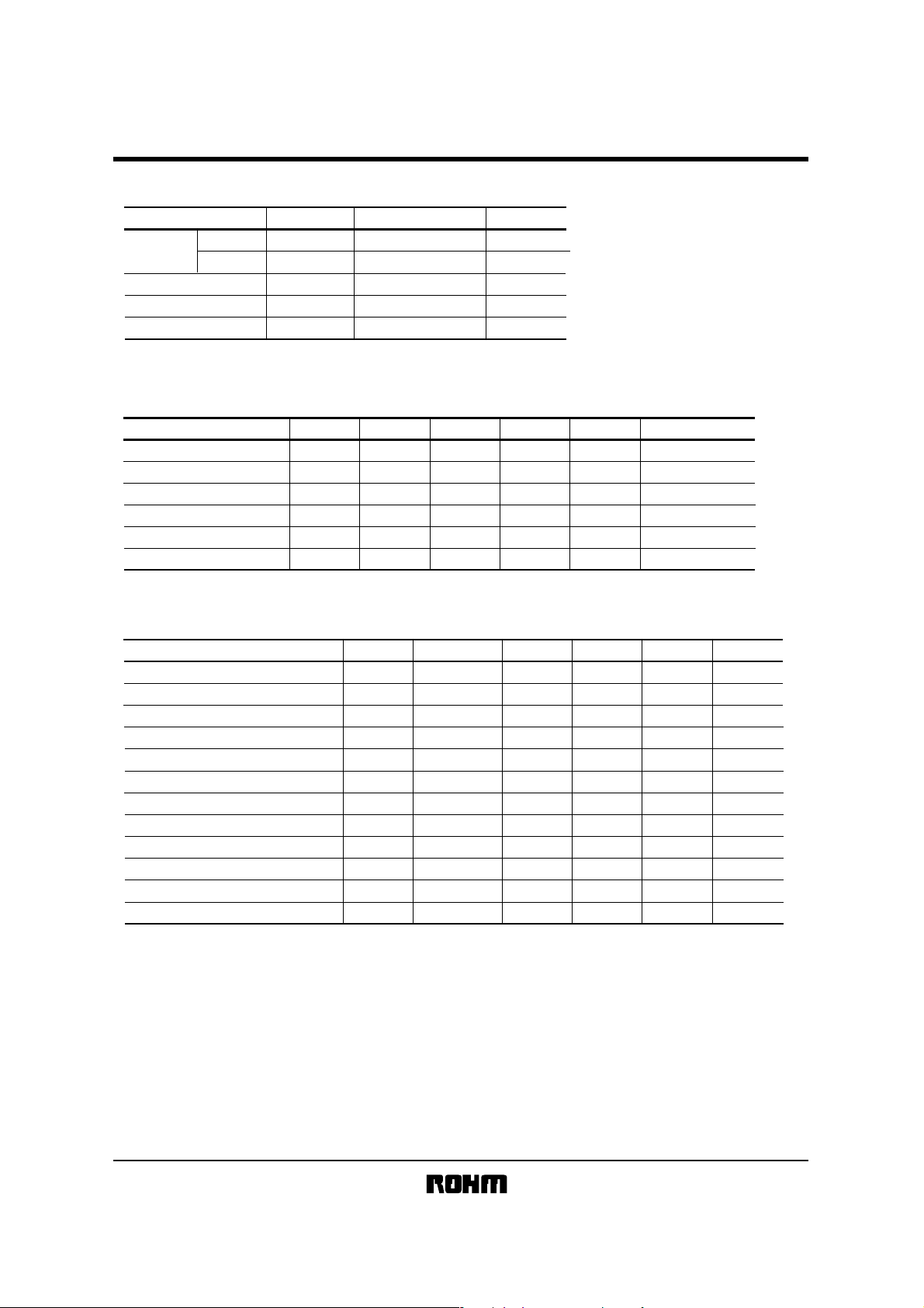
zAbsolute maximum ratings (Ta=25°C)
RCM1990U-A
Parameter
Power supply
voltage
Logic circuit
LCD drive
Input voltage
Operating temperature
Storage temperature
Symbol
V
DD
VDD-V
V
IN
T
opr
T
stg
EE
zElectrical characteristics (Ta=25°C, V
Parameter
High level input voltage
Low level input voltage
High level output voltage
Low level output voltage
Recommended LCD drive voltage
Current dissipation
Symbol
IH
V
V
IL
V
OH
V
OL
V
LCD
I
DD
zAC characteristics (Ta=25°C, V
Parameter
Shift frequency
High level lock width
Low level lock width
Data setup time
Clock setup time 1
Clock setup time 2
Data hold time
FLM setup time
FLM hold time
Clock rise / fall time
Output delay time
AC conversion signal
DD=5.0)
Limits
−0.3 to +7.0
−0.3 to +7.0
−0.3 to V
DD
+0.3
0 to +50
−10 to +60
DD=5.0V±0.25V)
Min.
3.5
−
4.6
−
−
−
Symbol
Applicable terminal
fCL
tCWH
CL1, CL2
tCWL
tSU
tSL
tLS
tDH
tFDS
tFDH
tct
CL1, CL2
tpd
fM
Typ.
CL2
CL2
DI
CL2
CL1
DI
FLM
FLM
DO
M
5.0
1.0
Unit
V
V
V
°C
°C
Max.
−
−
−
−
−
1.5
−
0.4
−
3.0
Min.
−
470
470
120
220
220
120
120
120
−
−
−
Unit
V
V
V
V
V
mA
Typ.
−
−
−
−
−
−
−
−
−
−
−
70
Conditions
IOH=−0.4mA
OH
=+0.4mA
I
Ta=25°C
f
CL
=1MHz, fM=70Hz
Max.
1
−
−
−
−
−
−
−
−
50
250
−
Unit
MHz
ns
ns
ns
ns
ns
ns
ns
ns
ns
ns
Hz
3/8
Page 4

Liquid crystal displays
zTiming characteristics
V
IH
V
IL
CL2
t
ct
DI
DO
CL1
FLM
zOptical characteristics (Ta=25°C)
RCM1990U-A
V
t
FDH
IH
ct
t
CWL
t
CWH
V
IH
V
IL
t
pd
V
OH
V
OL
V
IH
t
ct
t
SU
V
IH
V
IL
t
ct
t
DH
t
SL
t
LS
t
CWH
t
FDS
t
No. Parameter
1
2
3
Response speed
Viewing angle
Contrast ratio
Front-back
Right-left
(Note 1) Drive waveform
Static drive
1 / f
1 / 2V
−1 / 2V
V
OP
OP
0
OP
OP
−V
(Note 2) Definition of response speed
OFFON
I
OFF
Symbol
Temperature (°C)
Tr
Td
θ
φ 90 −
K2040
f = Frequency
T
25
0
25
0
25
25
25
Min.65Typ.
−
400 800
−
45
−
150
−
0
−
Unit Note
Max.
130
ms (Note 2)
100
300
60
deg
270
−
(Note 3)
K≥3
φ=180°
θ=10°
I
0.91
T
I
ON
r
0.11
T
d
4/8
Page 5

RCM1990U-A
Liquid crystal displays
Tr : Time for segment to darken 90% after selective waveform switches to non-selective waveform.
φ=180°, θ=10°
Td : Time for segment to darken 90% after selective waveform switches to non-selective waveform.
φ=180°, θ=10°
(Note 3) Definition of viewing angle (φ, θ)
Z
=
0°)
X(φ
Y(φ
=
90°)
θ
φ
Observer
X'(φ
=
270°)
LCD
Z'
Y'(φ
=
180°)
(1) φ : Angle subtended by the Y-Y’-axis and the observer’s position projected onto the XY-plane.
(2) θ : Angle subtended by observer and the normal Z-Z’axis. (X-axis and Y-axis are positive)
(3) Maximum viewing angle : The direction with highest contrast expressed at the time axis (refer to above table).
(Note 4) Definition of contrast ratio
<Definition>
Luminance during application
Contrast ratio =
of non-selective waveform
Luminance during application
of selective waveform
n
Except, n=1 with positive display and n=−1 with negative display.
< Measurement conditions >
Drive conditions : As per specifications
Viewing angle : φ=180°, θ=10°
(Note 5) Principles of optical measuring equipment
Characteristic
measuring
device
LCD-5100
Illumination
Specimen
Photometry
Constant temperature chamber
5/8
Page 6

Liquid crystal displays
zData format (data and display mapping)
D1 D17 D33 D209 D225 D241
D2 D18 D34 D210 D226 D242
D3 D19 D35 D211 D227 D243
D4 D20 D36 D212 D228 D244
D5 D245
D6 D246
D7 D247
D8 D248
D9 D249
D10 D250
D11 D251
D12
D13 D29 D45
D14 D30 D46
D15 D31 D47
D16 D32 D48
D49
D50
D51
D52
D61
D62
D63
D64
D65
D66
D67
D68
D77
D78
D79
D80
D81
D82
D83
D84
D93
D94
D95
D96
D177
D178
D179
D180
D189
D190
D191
D192
D193
D194
D195
D196
D221 D237 D253
D205
D222 D238 D254
D206
D223 D239 D255
D207
D224 D240 D256
D208
RCM1990U-A
D252
FIRST DATA
D2 D4 D6 D8 D254 D256D250 D252
COM.2 DATA
D1 D3 D5 D7 D253 D255D249 D251
COM.1 DATA
LAST DATA
6/8
Page 7

Liquid crystal displays
zTiming chart
M
FLM
CL1
f
CL
CL1
CL2
DATA
CL2
f
M
COM.2 DATA COM.1 DATA
RCM1990U-A
COM.1
COM.2
DATA
CL1
SEG.
(ON / ON)
SEG.
(ON / OFF)
SEG
(OFF / OFF)
D2 D4 D6 D2 D4 D6
D285 D286 D287 D288
No.2 panel
COM.2 DATA
D285 D286 D287 D288 D285 D286 D287 D288
D2 D4 D6
No.n panelNo.1 panel
D1 D3 D5
COM.1
DATA
7/8
Page 8

RCM1990U-A
Liquid crystal displays
zOperation notes
(1) Attention points in handling
•
Protect the module from strong shocks as they can cause damage or defective operation.
• The polarizing plate on the surface of the module is soft and can easily be scratched. Wipe away dirt and dust using an
alcohol-based cleanser.
• If the liquid crystal panel is damaged and liquid crystal contacts your clothing or body, wash immediately with soap and water.
• If the module is to be used for long periods subjected to direct sunlight, employ a filter to block the ultraviolet rays.
• Do not store the module in areas of high temperature or high humidity. Do not store the module in locations exposed to direct
sunlight or fluorescent light.
(2) Precautions during operation
• Do not connect or disconnect the module while the power supply is turned on.
•
Input the input signal after the module power supply is turned on. When turning it off, turn off the input signal first. Otherwise the
IC may be damaged by the latchup phenomenon.
(3) Precautions during installation
• Be careful to avoid damage from static electricity. A CMOS-IC is used in the modules circuitry that can be easily
damaged by static electricity.
• Do not remove the liquid crystal panel from the unit.
• Do not touch the back side of the liquid crystal panel.
(4) Precautions during unit assembly
•
In order to protect the polarizing plate from dirt or scratches, it is recommended to use a protective cover on the front surface.
8/8
Page 9

Appendix
No technical content pages of this document may be reproduced in any form or transmitted by any
means without prior permission of ROHM CO.,LTD.
The contents described herein are subject to change without notice. The specifications for the
product described in this document are for reference only. Upon actual use, therefore, please request
that specifications to be separately delivered.
Application circuit diagrams and circuit constants contained herein are shown as examples of standard
use and operation. Please pay careful attention to the peripheral conditions when designing circuits
and deciding upon circuit constants in the set.
Any data, including, but not limited to application circuit diagrams information, described herein
are intended only as illustrations of such devices and not as the specifications for such devices. ROHM
CO.,LTD. disclaims any warranty that any use of such devices shall be free from infringement of any
third party's intellectual property rights or other proprietary rights, and further, assumes no liability of
whatsoever nature in the event of any such infringement, or arising from or connected with or related
to the use of such devices.
Upon the sale of any such devices, other than for buyer's right to use such devices itself, resell or
otherwise dispose of the same, no express or implied right or license to practice or commercially
exploit any intellectual property rights or other proprietary rights owned or controlled by
ROHM CO., LTD. is granted to any such buyer.
Products listed in this document are no antiradiation design.
Notes
The products listed in this document are designed to be used with ordinary electronic equipment or devices
(such as audio visual equipment, office-automation equipment, communications devices, electrical
appliances and electronic toys).
Should you intend to use these products with equipment or devices which require an extremely high level of
reliability and the malfunction of with would directly endanger human life (such as medical instruments,
transportation equipment, aerospace machinery, nuclear-reactor controllers, fuel controllers and other
safety devices), please be sure to consult with our sales representative in advance.
About Export Control Order in Japan
Products described herein are the objects of controlled goods in Annex 1 (Item 16) of Export Trade Control
Order in Japan.
In case of export from Japan, please confirm if it applies to "objective" criteria or an "informed" (by MITI clause)
on the basis of "catch all controls for Non-Proliferation of Weapons of Mass Destruction.
Appendix1-Rev1.1
Page 10

WWW.ALLDATASHEET.COM
Copyright © Each Manufacturing Company.
All Datasheets cannot be modified without permission.
This datasheet has been download from :
www.AllDataSheet.com
100% Free DataSheet Search Site.
Free Download.
No Register.
Fast Search System.
www.AllDataSheet.com
 Loading...