

Page 1

NTE832 & NTE832SM
Integrated Circuit
Tone Decoder
Description:
The NTE832 and NTE832SM are general purpose tone decoders designed to provide a saturated
transistor switch to GND when an input signal is present within the passband. The circuit consists
of an I and Q detector driven by a voltage controlled oscillator which determines the center frequency
of the decoder. External components are used to independently set center frequency, bandwidth, and
output delay.
Features:
D Logic Compatible Output with 100mA Current Sinking Capability
D Bandwidth Adjustment from 0 to 14%
D Inherent Immunity to False Signals
D High Stable Center Frequency
D High Rejection of Out–Of–Band Signals and Noise
D Center Frequency Adjustable from 0.01Hz to 500kHz
D Frequecny Range Adjustable over 20:1 range by an External Resistor
D Available in Standard 8–Lead DIP (NTE832) and Surface Mount SOIC–8 (NTE832SM)
Applications:
D Touch Tone Decoder
D Precision Oscillator
D Frequency Monitoring and Control
D Wide Band FSK Demodulation
D Communications Paging Decoders
D Carrier Current Remote Controls
D Ultrasonic Controls (Remote TV, etc.)
Absolute Maximum Ratings:
Operating Voltage, V
Input Voltage, V
Output Voltage, V
Power Dissipation (Note 1), P
CC
IN
O
D
Operating Temperature Range, T
Storage Temperature Range, T
stg
opr
–10V to VCC +0.5V. . . . . . . . . . . . . . . . . . . . . . . . . . . . . . . . . . . . . . . . . . . . . . . . . . . .
0° to +70°C. . . . . . . . . . . . . . . . . . . . . . . . . . . . . . . . . . . . . . . . . . .
–65° to +150°C. . . . . . . . . . . . . . . . . . . . . . . . . . . . . . . . . . . . . . . . . .
10V. . . . . . . . . . . . . . . . . . . . . . . . . . . . . . . . . . . . . . . . . . . . . . . . . . . . . . . . . . . . .
15V. . . . . . . . . . . . . . . . . . . . . . . . . . . . . . . . . . . . . . . . . . . . . . . . . . . . . . . . . . . . . . . . .
300mW. . . . . . . . . . . . . . . . . . . . . . . . . . . . . . . . . . . . . . . . . . . . . . . . . . . .
Note 1. The maximum junction temperature of these devices is +100°C. For operating at elevated
temperatures, devices m ust b e d erated o n a thermal resistance o f + 187°C/W, junction–to–ambient.
Page 2
Electrical Characteristics: (VCC = 5V, TA = +25°C, unless otherwise specified)
Parameter Test Conditions Min Typ Max Unit
Power Supply Voltage 4.75 5.00 9.00 V
Power Supply Current, Quiescent RL = 20kΩ – 7 10 mA
Power Supply Current, Activated – 12 15 mA
Quiescent Power Dissipation – 35 – mW
Input Resistance 15 20 25 kΩ
Smallest Detectable Input Voltage IL = 100mA, fi = f
Largest No Output Input Voltage IC = 100mA, fi = f
Largest Simultaneous Outband Signal to Inband
RL = 20kΩ – +6 – dB
o
o
Signal Ratio
Minimum Input Signal to Widband Noise Ratio Bn = 140kHz – –6 – dB
Largest Detection Bandwidth 10 14 18 % of f
Largest Detection Bandwidth Skew – 2 3 % of f
Largest Detection Bandwidth with Variation with
Temperature
Largest Detection bandwidth with Variation with
4.75V to 6.75V – ±1 ±5 %/V
Supply Voltage
Highest Center Frequency RL = 20kΩ 100 500 – kHz
Center Frequency Stability 0° < TA , +70°C – 35±60 – ppm/°C
–55° < TA < +125°C – 35±140 – ppm/°C
Center Frequency Shift with Supply Voltage 4.75V to 6.75V – 0.4 2.0 %/V
Fastest ON–OFF Cycling Rate – fo/20 –
Output Leakage Current V8 = 15V – 0.01 25.0 µA
Output Saturation Voltage ei = 25mV, I8 = 30mA – 0.2 0.4 V
ei = 25mV, I8 = 100mA – 0.6 1.0 V
Output Fall Time – 30 – ns
Output Rise Time – 150 – ns
– 20 25 mV
10 15 – mV
– ±0.1 ±0.5 %/°C
rms
rms
o
o
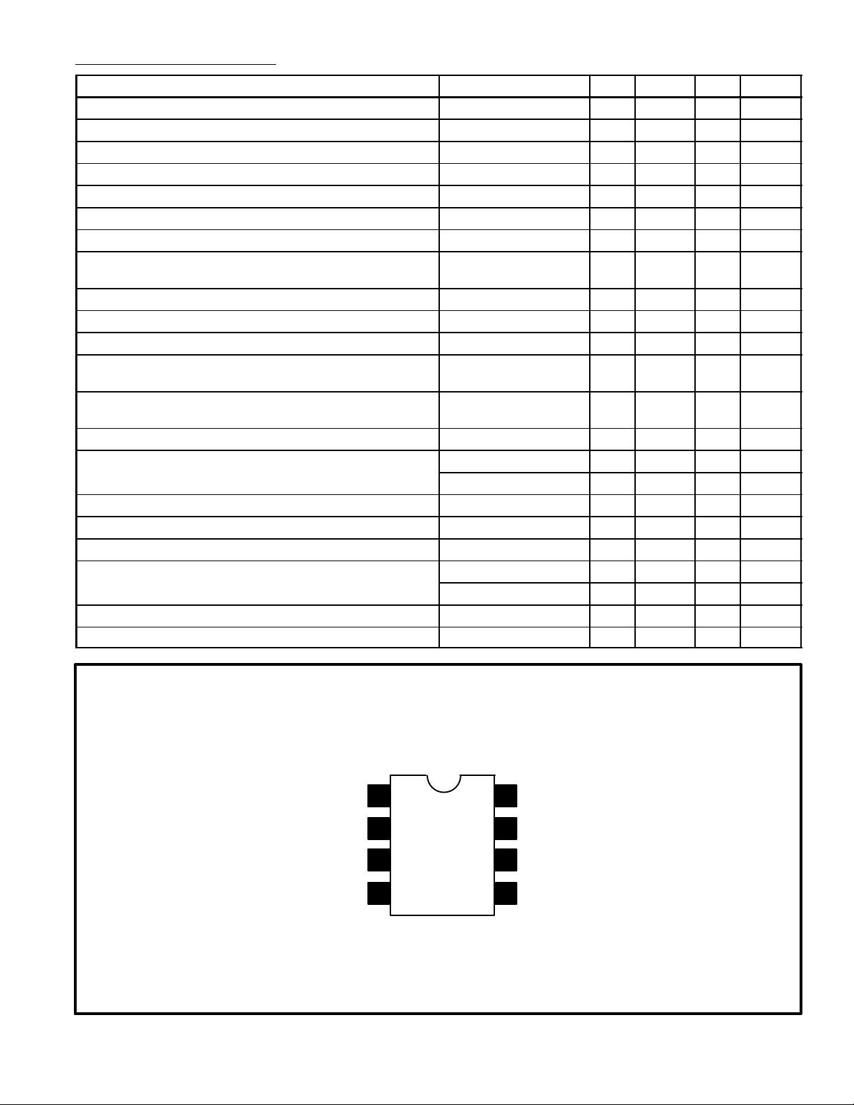
Output Filter
Loop Filter12
Input
V
CC
Pin Connection Diagram
8
7
3
4
6
5
Output
GND
Timing Capacitor
Timing Resistor
Page 3

NTE832 (8–Lead DIP)
85
.260 (6.6)
14
.100 (2.54)
.390 (9.9)
Max
.300 (7.62)
NTE832SM (SOIC–8)
.192 (4.9)
.300
(7.62)
.155
(3.93)
.145 (3.68)
85
.154
14
.050 (1.27) 016
.006 (.152)
NOTE: Pin1 on Beveled Edge
(3.91)
(.406)
061
(1.53)
.236
(5.99)
.198 (5.03)
 Loading...