

Page 1

NTE844
Integrated Circuit
Single Chip TV Chroma/Luminance Processor
Description:
The NTE844 is an integrated circuit in a 28–Lead DIP type package and contains all the required circuits functions between the video detector and the picture tube RGB driver stages of a color television
receiver . The NTE844 decodes the chrominance signals and then produces three different color signals that are internally combined with the luminance to develop the RGB signals. The picture saturation, hue and brightness DC controls are externally adjustable. The AFPC, ACC, Dynamic flesh control, Beam limiting and Gate black level (Brightness)control are servo loops used to stabilize the RGB
output and reduce frequent manual adjustment. The automatic beam limiter circuit reduces picture
contrast and brightness to prevent excessive drive output at the picture tube.
Features:
D All chroma processing and demodulating circuitry on a single chip.
D Phase–locked subcarrier regeneration utilizing sample–and–hold techniques.
D Supplementary ACC with overload detector
D Linear DC controls for chroma gain and tint
D Dynamic “flesh correction”
D Balanced chroma demodulators with low output impedance for direct coupling
D Internal RF filtering
D Few external components
D Automatic beam limiter
D Chroma luminance tracking picture control
Absolute Maximum Ratings:
DC Supply Voltage Between Pin23 and Pin8 14.0V. . . . . . . . . . . . . . . . . . . . . . . . . . . . . . . . . . . . . . . . .
Device Dissipation (Up to TA = +55°C), P
Derate Above TA = +55°C 13.3mW/°C. . . . . . . . . . . . . . . . . . . . . . . . . . . . . . . . . . . . . . . . . . . . . .
Operating Ambient Temperature Range, T
Storage Temperature Range, T
Lead Temperature (During Soldering, 1/16” from case, 10sec max), T
stg
D
opr
–40° to +85°C. . . . . . . . . . . . . . . . . . . . . . . . . . . . . . . . . .
–65° to +150°C. . . . . . . . . . . . . . . . . . . . . . . . . . . . . . . . . . . . . . . . . .
L
1.27W. . . . . . . . . . . . . . . . . . . . . . . . . . . . . . . . . . . . . . . . . . .
+265°C. . . . . . . . . . . . . . . . .
Page 2
Typical Performance Characteristics:
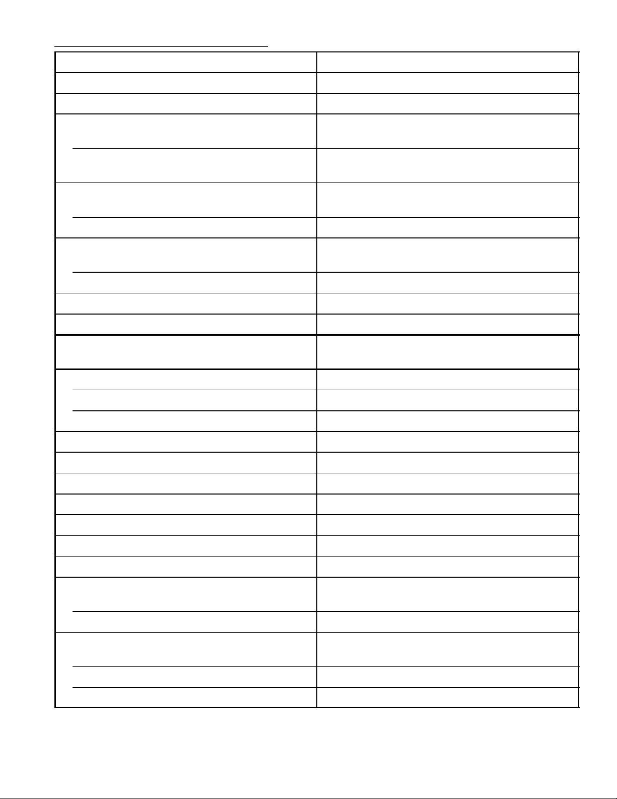
Function Typical Data
Nominal Supply 11.2V
Nominal Dissipation 500mW
Oscillator Stability
Supply Variation 10
–14
V 5Hz
Variation with Temperature
(∆T = +50°C) 25Hz
AFPC Characteristics
DC Loop Gain 33Hz/Degree
Pull–In Range ±500Hz
ACC Characteristic
100% Chroma Input Level 250mV
on Red Bar
p–p
3dB Point at 20% Nominal Input Level
Hue–Control Range 100°
Saturation–Control Range 40dB Min
Relative
Demodulator Characteristics:
Amplitude Angle
R – Y 1.0 93°
B – Y 1.2 2°
G – Y 0.3 258°
Bandwidth (Chroma) 900kHz
Flesh Control Primary Control in the +1 Half–Plane
Chroma Overload Control Two Levels
Picture Control 40dB
Brightness Control Black Level Clamped on 3V to 5V Level
Beam Limiting On Picture and Brightness Controls
Luma Bandwidth 5MHz Min
Sandcastle Input
1.2V to 2.3V Blanking
> 3.3V Burst gate
Maximum Linear Output
R 5V
G 3V
B 3.7V
Page 3
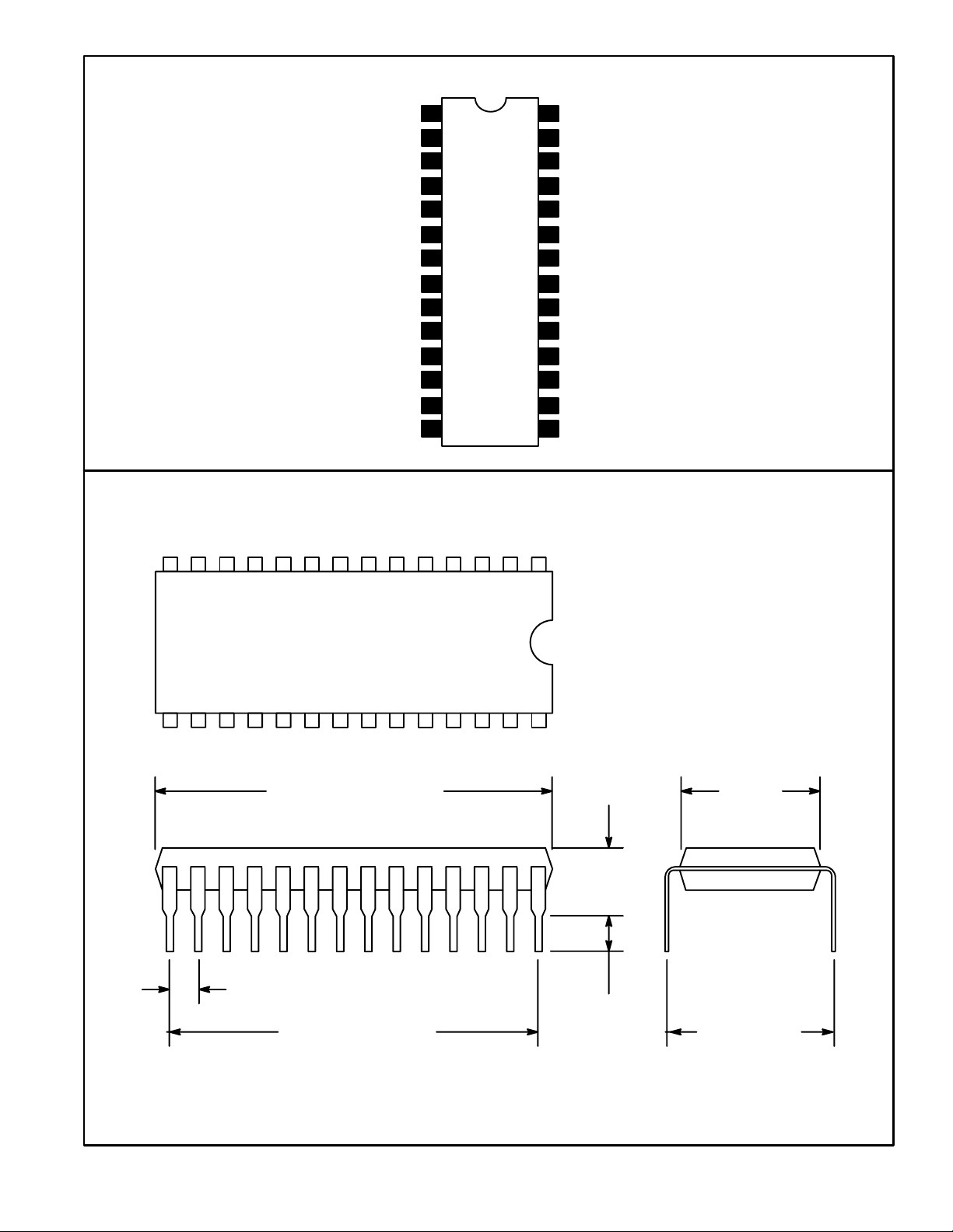
Pin Connection Diagram
Chroma Output
Chroma Control
Chroma Input
Overload Filter
OSC Input 90°
OSC Input 180°
1
2
3
4
5ACC, Killer Filter
6ACC, Killer Filter
7Sandcastle Pulse
8GND
9APC Filter
11
12
13OSC Output
14Tint Control
Beam Limiter
28
Luminance
27
Picture Control
26
25 Low Pass Filter
Bright Control
24
23
V
CC
22 Blue
21 Red
20 Green
Q Carrier Input10APC Filter
19
18 I Carrier Input
17 Demodulator Chroma Input
16 Overload, Flesh Disable
15 Carrier Output
14 1
15 28
1.469 (37.32) Max
.100 (2.54)
1.300 (33.02)
.250
(6.35)
.122
(3.1)
Min
.540
(13.7)
.600 (15.24)
 Loading...