

Page 1
DATA SHEET
L to S BAND LOW NOISE AMPLIFIER
N-CHANNEL HJ-FET
DESCRIPTION
NE34018 is a n-channel HJ-FET housed in MOLD package.
FEATURES
x
Low noise figure
NF = 0.6 dB TYP. at f = 2 GHz
x
High associated gain
Ga = 16 dB TYP. at f = 2 GHz
x
Gate width: Wg = 400 Pm
x
4 pins super mini mold
x
Tape & reel packaging only available
ORDERING INFORMATION
NE34018
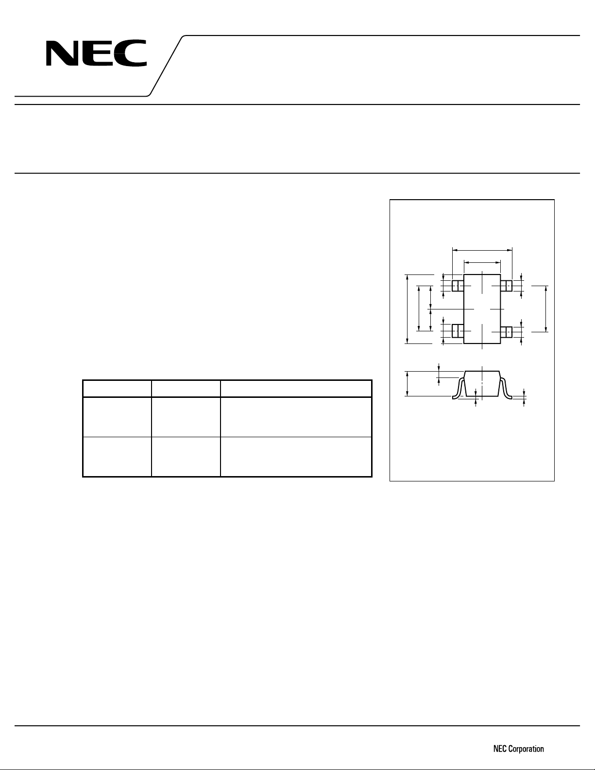
PACKAGE DIMENSIONS
in millimeters
2.1 ±0.2
1.25 ±0.1
+0.1
(1.25)
2.0 ±0.2
0.650.60
+0.1
–0.05
0.3
–0.05
0.4
0.3
V63
12
HJ-FET
+0.1
–0.05
0.3
(1.3)
+0.1
–0.05
43
0.3
PART NUMBER
QUANTITY PACKING STYLE
NE34018-T1 3 Kpcs/Reel. Embossed tape 8 mm wide. Pin 3
(Source), Pin 4 (Drain) face to
perforation side of the tape.
NE34018-T2 3 Kpcs/Reel. Embossed tape 8 mm wide. Pin 1
(Source), Pin 2 (Gate) face to
perforation side of the tape.
Please contact with responsible NEC person, if you require evaluation
*
sample. Unit sample quantity shall be 50 pcs. (Part number for sample
order: NE34018)
ABSOLUTE MAXIMUM RATINGS (TA = 25 qqqqC)
Drain to Source Voltage V
Gate to Source Voltage V
Gate Current I
Total Power Dissipation P
Channel Temperature T
Storage Temperature T
DS
GS
D
stg
4.0 V
3.0 V
ð
DSS
I
tot
ch
150 mW
125
65 to +125
ð
mA
C
q
C
q
0.9 ±0.1
0 to 0.1
PIN CONNECTIONS
1. Source
2. Gate
3. Source
4. Drain
+0.1
0.15
–0.05
Document No. P11618EJ3V0DS00 (3rd edition)
Date Published September 1997 N
Printed in Japan
1996©
Page 2
RECOMMENDED OPERATING CONDITION (TA = 25 qC)
CHARACTERISTIC SYMBOL MIN. TYP. MAX. UNIT
NE34018
Drain to Source Voltage V
Drain Current I
Input Power P
DS
D
in
ELECTRICAL CHARACTERISTICS (TA = 25 qqqqC)
CHARACTERISTIC SYMBOL MIN. TYP. MAX. UNIT TEST CONDITIONS
Gate to Source Leak Current
Saturated Drain Current
Gate to Source Cut off Voltage
Transconductance
Noise Figure
Associated Gain
Power Gain
Output Power at 1dB Gain
Compression Point
DSS
I
CLASSIFICATION
GSO
V
I
DSS
I
GS(off)
ð 0.5 10
30 120 mA
ð0.2 ð0.8 ð2.0 V
gm 30 ð mS
NF 0.6 1.0 dB
Ga 14 16 dB
Gs 18 dB
(1dB)
P
23V
530mA
+10 dBm
GS
= ð3 V
P
V
A
DS
= 2 V, VGS = 0 V
V
DS
= 2 V, ID = 100 PA
V
VDS = 2 V, ID = 5 mA
VDS = 2 V, ID = 5 mA, f = 2 GHz
15 dBm VDS = 3 V. IDS = 30 mA (RF off)
f = 2 GHz
RANK I
DSS
(mA) MARKING
63 30 to 65 V63
64 60 to 120 V64
2
Page 3
NE34018
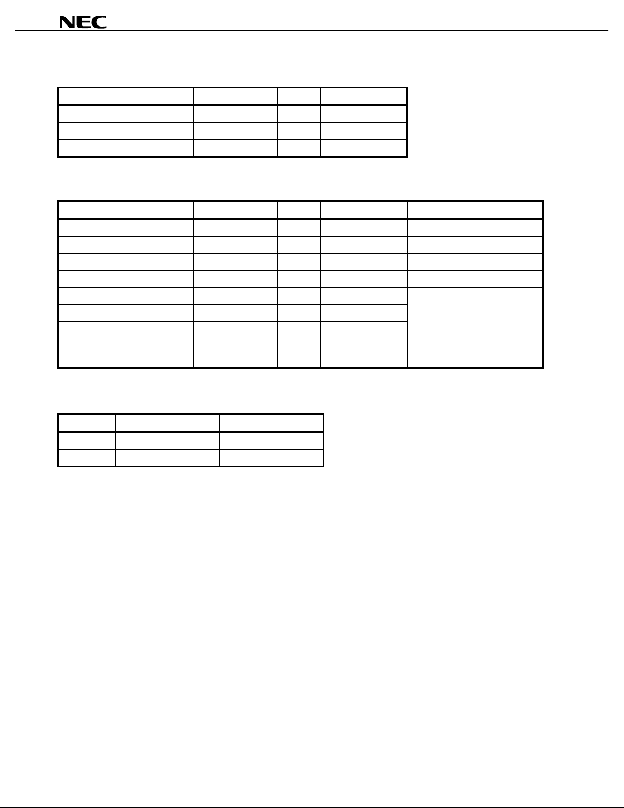
TYPICAL CHARACTERISTICS (TA = 25
TOTAL POWER DISSIPATION
vs. AMBIENT TEMPERATURE
qqqq
C)
DRAIN CURRENT vs.
DRAIN TO SOURCE VOLTAGE
250
100
VGS = 0 V
200
80
150
–0.2 V
60
100
- Total Power Dissipation - mW
50
tot
P
00
50 100 150 200
A
- Ambient Temperature - ˚C
T
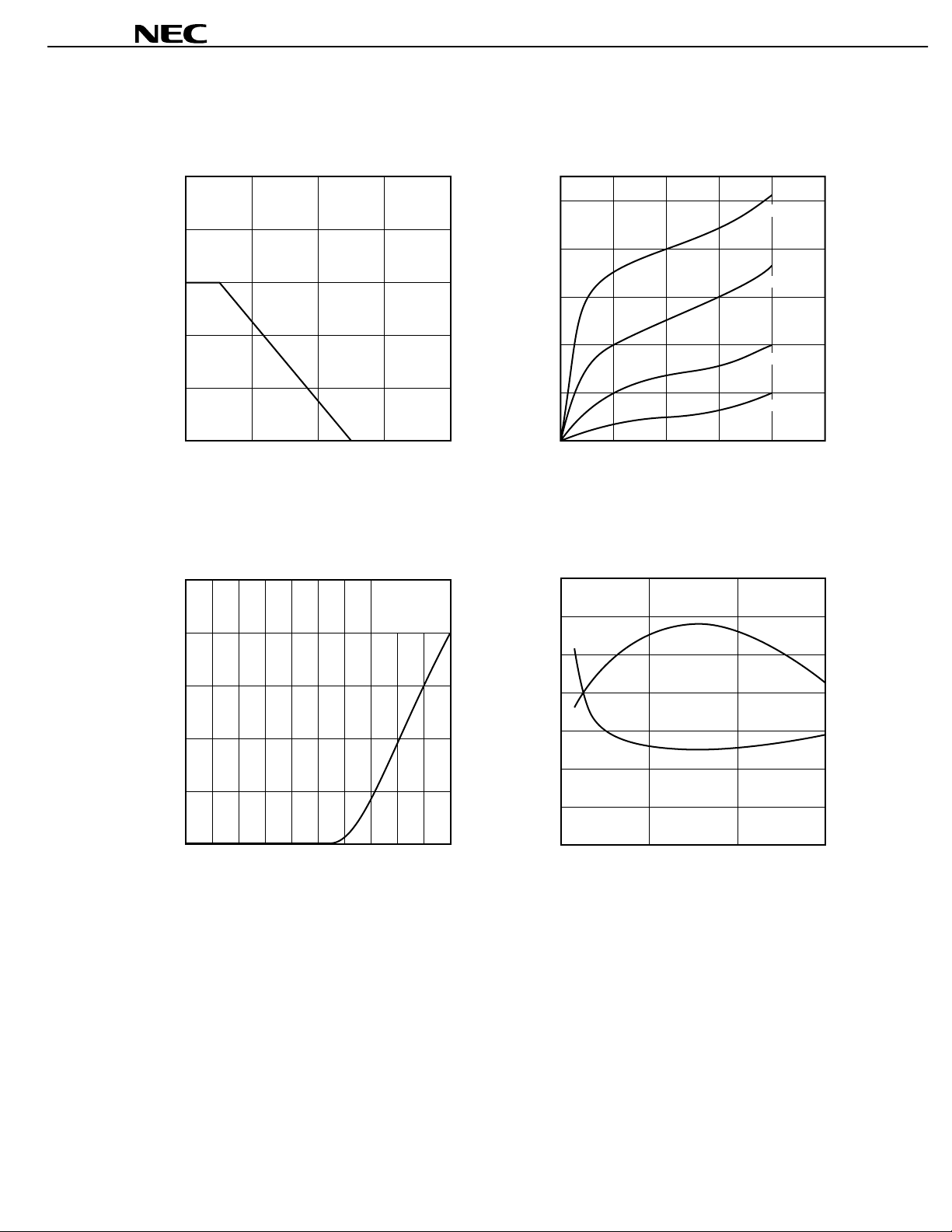
DRAIN CURRENT vs.
GATE TO SOURCE VOLTAGE
100
VDS = 2 V
40
- Drain Current - mA
D
I
20
–0.4 V
–0.6 V
12345
VDS - Drain to Source Voltage - V
NOISE FIGURE, ASSOCIATED GAIN vs.
DRAIN CURRENT
1.0
VDS = 2 V
0.9
f = 2 GHz
a
G
80
0.8
18
17
16
60
40
- Drain Current - mA
D
I
20
0
–2.0 –1.0 0
GS
- Gate to Source Voltage - V
V
0.7
0.6
NF - Noise Figure - dB
0.5
NF
0.4
01020
D
- Drain Current - mA
I
15
14
- Associated Gain - dB
a
G
30
3
Page 4

S-PARAMETER
MAG. AND ANG.
DS
V
= 2 V, ID = 5 mA
NE34018
FREQUENCY S
MHz MAG. ANG.
11
MAG. ANG.
(deg.)
21
S
MAG. ANG.
(deg.)
12
S
MAG. ANG.
(deg.)
500 .997 ð15.9 5.053 165.6 .020 82.6 .805 ð9.0
600 .994 ð19.1 5.070 162.8 .024 80.1 .801 ð10.7
700 .989 ð22.0 4.994 160.1 .027 79.0 .800 ð12.3
800 .983 ð25.1 4.992 157.4 .031 77.0 .798 ð13.9
900 .978 ð27.9 4.975 154.9 .035 75.1 .797 ð15.4
1000 .972 ð31.0 4.893 152.0 .039 73.7 .793 ð17.0
1100 .954 ð33.8 4.879 149.4 .042 71.8 .791 ð18.4
1200 .960 ð36.1 4.824 147.1 .045 71.0 .792 ð19.6
1300 .951 ð38.8 4.790 144.6 .048 69.9 .785 ð20.9
1400 .945 ð41.2 4.746 142.2 .050 68.9 .782 ð22.2
1500 .934 ð43.7 4.696 139.8 .054 68.2 .780 ð23.4
1600 .926 ð46.3 4.655 137.4 .056 65.4 .777 ð24.4
1700 .914 ð48.4 4.588 135.1 .058 65.7 .775 ð25.5
1800 .901 ð50.7 4.526 132.8 .061 63.9 .769 ð26.3
1900 .887 ð52.9 4.463 130.7 .063 62.7 .766 ð27.3
2000 .807 ð58.3 4.308 124.8 .064 58.5 .699 ð27.7
2100 .787 ð60.6 4.241 122.6 .066 57.1 .697 ð28.6
2200 .775 ð62.9 4.193 120.4 .067 56.1 .685 ð29.8
2300 .755 ð64.7 4.122 118.4 .070 55.8 .680 ð30.2
2400 .745 ð66.8 4.069 116.5 .070 54.8 .675 ð31.1
2500 .732 ð68.5 4.017 114.7 .072 55.0 .671 ð31.9
2600 .720 ð70.8 3.977 112.7 .074 54.5 .666 ð32.5
2700 .706 ð72.8 3.913 110.7 .075 53.1 .657 ð33.6
2800 .691 ð75.3 3.892 108.9 .077 53.1 .656 ð34.1
2900 .677 ð77.2 3.833 106.9 .078 51.7 .650 ð34.8
3000 .657 ð79.5 3.783 105.0 .080 51.5 .642 ð35.6
22
S
(deg.)
4
Page 5

AMP. PARAMETERS
DS
V
= 2 V, ID = 5 mA
NE34018
FREQUENCY
MHz
GUmaxdBGAmaxdB~S21~
dB
2
~S12~
dB
2
K DelaynsMason’s U
dB
G1
dB
500 40.42 14.07 ð34.10 .02 .078 21.81 4.53
600 37.65 14.10 ð32.49 .04 .078 19.09 4.46
700 35.02 13.97 ð31.28 .05 .074 16.61 4.44
800 33.18 13.97 ð30.09 .07 .074 14.81 4.40
900 31.99 13.94 ð29.02 .09 .070 13.68 4.37
1000 30.73 13.79 ð28.27 .10 .079 12.63 4.31
1100 28.48 13.77 ð27.56 .14 .072 10.45 4.26
1200 28.95 13.67 ð26.99 .13 .065 11.01 4.28
1300 28.01 13.61 ð26.40 .14 .068 10.24 4.16
1400 27.36 13.53 ð25.95 .15 .068 9.73 4.11
1500 26.48 13.43 ð25.35 .16 .065 8.97 4.08
1600 25.87 13.36 ð25.02 .19 .067 8.48 4.02
1700 25.04 13.23 ð24.73 .20 .064 7.82 3.98
1800 24.27 13.11 ð24.35 .23 .065 7.27 3.88
1900 23.54 12.99 ð23.99 .26 .057 6.72 3.83
2000 20.17 12.68 ð23.88 .47 .164 27.008 4.57 2.92
2100 19.63 12.55 ð23.67 .50 .063 25.640 4.20 2.89
2200 19.19 12.45 ð23.48 .52 .059 25.263 3.99 2.75
2300 18.67 12.30 ð23.16 .55 .056 24.878 3.67 2.70
2400 18.34 12.19 ð23.05 .57 .054 24.607 3.51 2.64
2500 18.00 12.08 ð22.91 .59 .049 25.175 3.33 2.59
2600 17.70 11.99 ð22.65 .60 .056 25.565 3.17 2.54
2700 17.30 11.85 ð22.46 .63 .055 24.387 3.00 2.45
2800 17.07 11.80 ð22.24 .63 .050 25.422 2.82 2.45
2900 16.71 11.67 ð22.10 .67 .057 24.032 2.66 2.38
3000 16.31 11.56 ð21.89 .69 .053 23.850 2.45 2.30
G2
dB
5
Page 6

S-PARAMETER
MAG. AND ANG.
DS
V
= 2 V, ID = 10 mA
NE34018
FREQUENCY S
MHz MAG. ANG.
11
MAG. ANG.
(deg.)
21
S
MAG. ANG.
(deg.)
12
S
MAG. ANG.
(deg.)
500 .988 ð18.2 7.217 163.2 .018 80.7 .722 ð9.7
600 .982 ð21.8 7.184 160.0 .022 79.7 .717 ð11.6
700 .974 ð25.0 7.070 156.9 .025 77.5 .717 ð13.4
800 .964 ð28.4 6.995 153.8 .029 77.4 .711 ð15.0
900 .954 ð31.5 6.928 150.8 .032 75.0 .710 ð16.6
1000 .942 ð34.7 6.797 147.9 .035 74.4 .705 ð18.1
1100 .924 ð37.8 6.707 144.9 .038 71.9 .702 ð19.7
1200 .922 ð40.4 6.607 142.3 .042 72.7 .700 ð20.8
1300 .909 ð43.2 6.506 139.5 .044 70.6 .694 ð21.9
1400 .897 ð45.8 6.387 136.8 .046 70.4 .690 ð23.4
1500 .880 ð48.4 6.286 134.4 .049 68.6 .688 ð24.4
1600 .868 ð50.9 6.179 131.7 .052 68.2 .683 ð25.3
1700 .851 ð53.2 6.055 129.3 .053 67.1 .680 ð26.4
1800 .836 ð55.3 5.937 126.9 .055 66.5 .675 ð27.1
1900 .817 ð57.6 5.829 124.7 .058 65.7 .671 ð27.8
2000 .735 ð63.0 5.570 119.4 .058 61.7 .604 ð27.3
2100 .710 ð65.4 5.453 117.0 .060 61.2 .600 ð28.1
2200 .697 ð67.6 5.354 114.8 .061 60.0 .590 ð29.1
2300 .675 ð69.4 5.242 112.8 .064 59.6 .586 ð29.5
2400 .662 ð71.5 5.148 110.9 .065 59.4 .580 ð30.1
2500 .647 ð73.0 5.057 109.0 .067 59.5 .577 ð30.6
2600 .634 ð75.2 4.977 107.1 .069 58.6 .573 ð31.2
2700 .617 ð77.3 4.880 105.1 .071 58.7 .567 ð32.1
2800 .602 ð79.5 4.819 103.4 .073 58.4 .567 ð32.5
2900 .584 ð81.5 4.734 101.4 .075 57.6 .559 ð33.2
3000 .564 ð83.6 4.640 99.5 .076 56.6 .553 ð33.8
22
S
(deg.)
6
Page 7

AMP. PARAMETERS
DS
V
= 2 V, ID = 10 mA
NE34018
FREQUENCY
MHz
GUmaxdBGAmaxdB~S21~
dB
2
~S12~
dB
2
K DelaynsMason’s U
dB
G1
dB
500 36.72 17.17 ð34.88 .08 .089 16.35 3.20
600 34.68 17.13 ð33.03 .10 .089 14.42 3.14
700 33.00 16.99 ð31.95 .13 .086 12.88 3.13
800 31.44 16.90 ð30.71 .13 .087 11.48 3.06
900 30.33 16.81 ð29.79 .16 .083 10.48 3.04
1000 29.14 16.65 ð29.03 .18 .081 9.51 2.98
1100 27.83 16.53 ð28.43 .22 .081 8.35 2.95
1200 27.55 16.40 ð27.64 .21 .074 8.23 2.93
1300 26.71 16.27 ð27.23 .24 .077 7.59 2.86
1400 25.99 16.11 ð26.69 .25 .075 7.08 2.81
1500 25.23 15.97 ð26.24 .29 .068 6.48 2.79
1600 24.63 15.82 ð25.75 .30 .072 6.08 2.73
1700 23.92 15.64 ð25.45 .33 .068 5.58 2.70
1800 23.33 15.47 ð25.15 .36 .067 5.21 2.65
1900 22.70 15.31 ð24.68 .38 .061 4.78 2.60
2000 20.26 14.92 ð24.71 .60 .148 28.512 3.37 1.97
2100 19.72 14.73 ð24.48 .64 .066 27.821 3.05 1.94
2200 19.32 14.57 ð24.29 .67 .062 26.935 2.89 1.86
2300 18.85 14.39 ð23.88 .69 .054 26.358 2.64 1.83
2400 18.52 14.23 ð23.71 .71 .054 26.420 2.50 1.78
2500 18.19 14.08 ð23.54 .73 .051 26.588 2.36 1.76
2600 17.90 13.94 ð23.21 .74 .054 26.416 2.23 1.73
2700 17.53 13.77 ð23.02 .76 .056 26.641 2.08 1.69
2800 17.29 13.66 ð22.78 .77 .048 27.042 1.95 1.68
2900 16.94 13.50 ð22.53 .80 .056 26.181 1.81 1.63
3000 16.58 13.33 ð22.43 .83 .053 24.840 1.66 1.59
G2
dB
7
Page 8

S-PARAMETER
MAG. AND ANG.
DS
V
= 2 V, ID = 20 mA
NE34018
FREQUENCY S
MHz MAG. ANG.
11
MAG. ANG.
(deg.)
21
S
MAG. ANG.
(deg.)
12
S
MAG. ANG.
(deg.)
500 .978 ð20.1 9.298 160.9 .017 82.7 .637 ð10.0
600 .968 ð23.9 9.160 157.3 .021 80.2 .635 ð11.8
700 .954 ð27.5 9.000 153.9 .023 79.8 .632 ð13.7
800 .943 ð31.1 8.848 150.5 .026 77.7 .627 ð15.3
900 .929 ð34.4 8.700 147.3 .029 76.6 .627 ð16.8
1000 .913 ð37.7 8.501 144.0 .032 74.7 .621 ð18.0
1100 .891 ð40.8 8.335 141.0 .035 74.7 .618 ð19.6
1200 .884 ð43.5 8.162 138.0 .037 74.3 .617 ð20.5
1300 .865 ð46.4 7.972 135.2 .040 74.2 .613 ð21.7
1400 .849 ð48.9 7.801 132.3 .042 71.9 .607 ð23.0
1500 .830 ð51.4 7.607 129.8 .045 71.7 .606 ð24.0
1600 .815 ð54.0 7.440 127.1 .047 71.1 .603 ð24.7
1700 .793 ð56.3 7.247 124.7 .049 70.0 .599 ð25.6
1800 .775 ð58.3 7.074 122.2 .051 69.4 .598 ð26.2
1900 .754 ð60.4 6.913 119.9 .053 68.8 .593 ð26.8
2000 .674 ð65.8 6.573 115.0 .053 66.1 .528 ð25.1
2100 .648 ð68.1 6.417 112.7 .056 65.5 .526 ð25.7
2200 .632 ð70.2 6.265 110.5 .057 64.5 .516 ð26.7
2300 .610 ð71.9 6.113 108.6 .059 64.6 .515 ð26.7
2400 .596 ð73.7 5.976 106.7 .061 64.6 .510 ð27.3
2500 .579 ð75.2 5.849 105.0 .063 65.0 .509 ð27.8
2600 .566 ð77.1 5.727 103.1 .065 63.8 .507 ð28.2
2700 .548 ð79.3 5.610 101.1 .068 64.3 .502 ð29.1
2800 .532 ð81.2 5.499 99.4 .069 63.3 .502 ð29.4
2900 .515 ð83.0 5.399 97.5 .071 64.1 .498 ð30.0
3000 .496 ð84.8 5.272 95.7 .073 62.4 .493 ð30.4
22
S
(deg.)
8
Page 9

AMP. PARAMETERS
DS
V
= 2 V, ID = 20 mA
NE34018
FREQUENCY
MHz
GUmaxdBGAmaxdB~S21~
dB
2
~S12~
dB
2
K DelaynsMason’s U
dB
G1
dB
500 35.28 19.37 ð35.33 .12 .098 13.65 2.26
600 33.54 19.24 ð33.71 .16 .098 12.07 2.24
700 31.81 19.09 ð32.71 .18 .097 10.51 2.22
800 30.66 18.94 ð31.61 .21 .094 9.55 2.17
900 29.62 18.79 ð30.78 .24 .088 8.66 2.17
1000 28.49 18.59 ð29.78 .28 .092 7.78 2.12
1100 27.38 18.42 ð29.14 .31 .085 6.86 2.09
1200 26.91 18.24 ð28.63 .32 .082 6.59 2.08
1300 26.08 18.03 ð28.04 .34 .079 6.00 2.05
1400 25.38 17.84 ð27.49 .38 .079 5.53 2.00
1500 24.70 17.62 ð26.88 .40 .071 5.08 1.99
1600 24.13 17.43 ð26.49 .42 .073 4.74 1.97
1700 23.43 17.20 ð26.16 .46 .068 4.30 1.93
1800 22.90 16.99 ð25.88 .49 .070 3.98 1.92
1900 22.33 16.79 ð25.46 .52 .062 3.66 1.88
2000 20.40 16.35 ð25.44 .72 .137 29.694 2.63 1.42
2100 19.92 16.15 ð25.02 .75 .064 28.981 2.37 1.41
2200 19.50 15.94 ð24.90 .79 .062 27.785 2.21 1.35
2300 19.08 15.72 ð24.53 .81 .052 27.569 2.02 1.34
2400 18.74 15.53 ð24.25 .82 .053 27.816 1.91 1.31
2500 18.41 15.34 ð23.96 .84 .048 28.156 1.77 1.30
2600 18.13 15.16 ð23.71 .85 .053 27.486 1.68 1.29
2700 17.79 14.98 ð23.29 .86 .053 28.589 1.55 1.26
2800 17.51 14.80 ð23.18 .88 .047 27.386 1.44 1.26
2900 17.22 14.65 ð22.93 .89 .054 28.295 1.34 1.24
3000 16.88 14.44 ð22.71 .92 .050 26.323 1.22 1.21
G2
dB
9
Page 10

S-PARAMETERS
MAG. AND ANG.
DS
V
= 3 V, ID = 5 mA
NE34018
FREQUENCY S
MHz MAG. ANG.
11
MAG. ANG.
(deg.)
21
S
MAG. ANG.
(deg.)
12
S
MAG. ANG.
(deg.)
500 .991 ð15.2 5.038 165.1 .020 79.3 .817 ð9.8
600 .984 ð18.1 5.040 162.2 .024 79.0 .812 ð11.7
700 .982 ð20.8 4.984 159.4 .027 76.7 .809 ð13.6
800 .973 ð23.8 4.958 156.6 .031 77.2 .807 ð15.2
900 .970 ð26.6 4.958 154.1 .034 74.4 .806 ð16.8
1000 .964 ð29.0 4.892 151.4 .038 73.4 .803 ð18.6
1100 .944 ð32.0 4.850 148.6 .040 70.8 .797 ð20.1
1200 .947 ð34.2 4.791 146.2 .044 70.3 .794 ð21.5
1300 .938 ð36.7 4.764 143.8 .048 69.6 .791 ð23.1
1400 .929 ð38.9 4.722 141.4 .050 68.9 .788 ð24.3
1500 .920 ð41.3 4.675 139.0 .052 67.2 .789 ð25.7
1600 .911 ð43.6 4.640 136.6 .056 66.5 .786 ð27.2
1700 .901 ð45.7 4.579 134.4 .058 65.1 .780 ð28.3
1800 .890 ð47.9 4.527 132.2 .061 64.1 .778 ð29.4
1900 .878 ð49.8 4.473 130.0 .063 62.9 .775 ð30.5
2000 .815 ð57.5 4.306 123.9 .063 58.4 .687 ð29.1
22
S
(deg.)
AMP. PARAMETERS
FREQUENCY
MHz
GUmaxdBGAmaxdB~S21~
dB
2
~S12~
dB
2
K DelaynsMason’s U
dB
G1
dB
500 36.20 14.05 ð34.16 .09 .080 39.523 17.38 4.78
600 33.77 14.05 ð32.46 .09 .080 15.04 4.69
700 32.94 13.95 ð31.29 .11 .077 14.37 4.62
800 31.24 13.91 ð30.13 .10 .077 12.75 4.58
900 30.67 13.91 ð29.27 .12 .071 12.22 4.55
1000 29.74 13.79 ð28.52 .13 .074 11.46 4.49
1100 27.71 13.72 ð27.86 .18 .077 9.61 4.38
1200 27.80 13.61 ð27.10 .17 .066 9.87 4.32
1300 27.04 13.56 ð26.43 .17 .069 9.22 4.26
1400 26.34 13.48 ð26.01 .18 .066 8.64 4.22
1500 25.76 13.40 ð25.69 .20 .066 8.12 4.24
1600 25.18 13.33 ð25.10 .21 .067 7.68 4.18
1700 24.52 13.21 ð24.80 .23 .061 7.24 4.07
1800 24.00 13.12 ð24.36 .24 .061 6.84 4.05
1900 23.40 13.01 ð24.05 .26 .062 6.41 3.99
2000 20.18 12.68 ð23.97 .47 .169 27.557 4.73 2.77
G2
dB
10
Page 11

S-PARAMETERS
MAG. AND ANG.
DS
V
= 3 V, ID = 10 mA
NE34018
FREQUENCY S
MHz MAG. ANG.
11
MAG. ANG.
(deg.)
21
S
MAG. ANG.
(deg.)
12
S
MAG. ANG.
(deg.)
500 .982 ð17.5 7.163 162.7 .019 82.5 .736 ð10.5
600 .973 ð20.9 7.082 159.4 .022 79.5 .732 ð12.4
700 .965 ð24.0 7.001 156.2 .025 76.7 .729 ð14.4
800 .953 ð27.2 6.905 153.1 .028 75.6 .725 ð16.2
900 .944 ð30.3 6.849 150.2 .032 74.8 .720 ð17.8
1000 .934 ð33.0 6.738 147.3 .035 73.4 .717 ð19.5
1100 .913 ð36.3 6.624 144.1 .037 72.4 .713 ð21.2
1200 .909 ð38.6 6.514 141.6 .040 70.8 .708 ð22.5
1300 .894 ð41.3 6.415 138.7 .043 71.0 .706 ð24.0
1400 .882 ð43.7 6.323 136.2 .046 69.7 .702 ð25.2
1500 .866 ð46.2 6.219 133.6 .048 67.6 .700 ð26.5
1600 .853 ð48.5 6.123 131.0 .050 67.0 .697 ð27.9
1700 .837 ð50.6 6.004 128.8 .052 67.2 .692 ð29.0
1800 .823 ð52.8 5.897 126.4 .055 66.5 .689 ð29.9
1900 .808 ð54.7 5.800 124.1 .057 65.4 .685 ð31.0
2000 .747 ð62.5 5.514 118.6 .058 61.2 .593 ð28.2
22
S
(deg.)
AMP. PARAMETERS
FREQUENCY
MHz
GUmaxdBGAmaxdB~S21~
dB
2
~S12~
dB
2
K DelaynsMason’s U
dB
G1
dB
500 35.08 17.10 ð34.56 .09 .093 14.59 3.38
600 33.03 17.00 ð33.28 .13 .093 12.69 3.34
700 31.88 16.90 ð32.21 .16 .088 11.69 3.29
800 30.40 16.78 ð30.97 .18 .086 10.38 3.24
900 29.55 16.71 ð29.89 .19 .081 9.66 3.18
1000 28.64 16.57 ð29.23 .21 .082 8.93 3.14
1100 27.29 16.42 ð28.63 .24 .088 7.79 3.08
1200 26.89 16.28 ð27.89 .26 .070 7.59 3.02
1300 26.11 16.14 ð27.29 .27 .080 6.97 3.00
1400 25.51 16.02 ð26.83 .29 .068 6.53 2.95
1500 24.82 15.87 ð26.32 .32 .074 6.02 2.92
1600 24.28 15.74 ð25.98 .34 .072 5.65 2.89
1700 23.64 15.57 ð25.60 .35 .062 5.25 2.83
1800 23.12 15.41 ð25.23 .37 .066 4.91 2.80
1900 22.61 15.27 ð24.82 .39 .064 4.59 2.75
2000 20.25 14.83 ð24.80 .61 .152 28.504 3.55 1.88
G2
dB
11
Page 12

S-PARAMETERS
MAG. AND ANG.
DS
V
= 3 V, ID = 30 mA
NE34018
FREQUENCY S
MHz MAG. ANG.
11
MAG. ANG.
(deg.)
21
S
MAG. ANG.
(deg.)
12
S
MAG. ANG.
(deg.)
500 .974 –20.9 10.260 159.9 .016 82.5 .625 –9.7
600 .961 –24.8 10.103 156.1 .018 80.4 .620 –11.5
700 .947 –28.5 9.901 152.5 .022 79.9 .618 –13.3
800 .931 –32.2 9.688 149.1 .025 78.7 .614 –14.8
900 .915 –35.5 9.505 145.6 .028 76.8 .614 –16.2
1000 .894 –39.0 9.260 142.3 .030 76.4 .608 –17.7
1100 .875 –41.9 9.057 139.2 .032 76.3 .607 –18.9
1200 .863 –44.7 8.850 136.2 .035 74.8 .605 –19.8
1300 .843 –47.5 8.618 133.3 .036 73.8 .599 –20.9
1400 .825 –50.1 8.399 130.4 .039 73.5 .595 –21.9
1500 .806 –52.5 8.182 127.9 .042 72.1 .594 –22.8
1600 .788 –55.2 7.980 125.2 .044 72.6 .593 –23.6
1700 .768 –57.1 7.770 122.6 .046 71.8 .590 –24.4
1800 .747 –59.2 7.550 120.2 .048 72.5 .588 –24.9
1900 .726 –61.2 7.356 118.1 .050 71.2 .586 –25.5
2000 .646 –66.6 6.989 113.2 .050 67.4 .521 –23.5
22
S
(deg.)
AMP. PARAMETERS
FREQUENCY
MHz
GUmaxdBGAmaxdB~S21~
dB
2
~S12~
dB
2
K DelaynsMason’s U
dB
G1
dB
500 35.31 20.22 –36.03 .15 .103 12.94 2.15
600 33.31 20.09 –34.85 .19 .103 11.12 2.11
700 31.84 19.91 –33.23 .21 .100 9.83 2.09
800 30.56 19.72 –32.13 .25 .097 8.77 2.06
900 29.50 19.56 –31.12 .28 .095 7.88 2.05
1000 28.32 19.33 –30.59 .32 .093 6.98 2.01
1100 27.43 19.14 –29.81 .34 .086 6.29 2.00
1200 26.85 18.94 –29.05 .37 .085 5.93 1.98
1300 26.02 18.71 –28.76 .40 .079 5.38 1.93
1400 25.34 18.48 –28.20 .43 .081 4.96 1.90
1500 24.70 18.26 –27.62 .46 .070 4.55 1.89
1600 24.14 18.04 –27.03 .47 .073 4.21 1.88
1700 23.53 17.81 –26.74 .51 .071 3.87 1.86
1800 22.94 17.56 –26.38 .53 .068 3.54 1.84
1900 22.41 17.33 –26.03 .56 .059 3.25 1.82
2000 20.61 16.89 –25.99 .78 .135 29.365 2.35 1.37
G2
dB
12
Page 13

NOISE PARAMETER
VDS = 2 V, ID = 5 mA
0.9 0.51 21.2 0.69 15 0.26
1.0 0.52 20.8 0.68 17 0.25
1.5 0.57 18.2 0.63 25 0.24
2.0 0.61 16.2 0.61 35 0.23
2.5 0.62 14.4 0.56 46 0.21
3.0 0.65 13.3 0.44 59 0.17
VDS = 2 V, ID = 10 mA
min
min
NE34018
*
(dB)Freq (GHz)
opt
MAG. ANG. (deg.)
*
(dB)Freq (GHz)
opt
MAG. ANG. (deg.)
Rh/50Ga (dB)NF
h
R
/50Ga (dB)NF
0.9 0.43 22.0 0.62 13 0.20
1.0 0.44 21.6 0.61 14 0.20
1.5 0.49 19.0 0.58 23 0.19
2.0 0.52 16.5 0.57 34 0.18
2.5 0.54 14.9 0.52 45 0.17
3.0 0.57 13.8 0.36 57 0.13
VDS = 3 V, ID = 10 mA
0.9 0.43 22.2 0.61 11 0.21
1.0 0.44 21.8 0.60 13 0.20
1.5 0.49 19.2 0.57 22 0.20
2.0 0.52 16.7 0.57 33 0.19
2.5 0.54 15.1 0.52 45 0.18
3.0 0.57 14.0 0.37 58 0.14
min
*
(dB)Freq (GHz)
opt
h
R
/50Ga (dB)NF
MAG. ANG. (deg.)
13
Page 14

RECOMMENDED SOLDERING CONDITIONS
The following conditions (see table below) must be met when soldering this product.
Please consult with our sales offices in case other soldering process is used, or in case soldering is done under
different conditions.
<TYPES OF SURFACE MOUNT DEVICE>
For more details, refer to our document “SEMICONDUCTOR DEVICE MOUNTING TECHNOLOGY MANUAL”
(C10535E).
Soldering process Soldering conditions Symbol
NE34018
VPS Package peak temperature: 215 qC,
Time: 40 seconds MAX. (200 qC MIN.),
Number of times: 3, Number of days: not limited*
Wave soldering Soldering bath temperature: 260 qC MAX.,
Time: 10 seconds MAX., Number of times: 1,
Number of days: not limited*
Infrared ray reflow Peak package’s surface temperature: 230 qC below,
Reflow time: 30 seconds or below (210 qC or higher),
Number of reflow process: 3, Exposure limit*: None
Partial heating method Terminal temperature: 230 qC or below,
Flow time: 10 seconds or below, Exposure limit*: None
Exposure limit before soldering after dry-pack package is opened.
*
VP15-00-3
WS60-00-1
IR30-00-3
Storage conditions: 25 qC and relative humidity at 65 % or less.
Do not apply more than a single process at once, except for “Partial heating method”.
Note
PRECAUTION Avoid high static voltage and electric fields, because this device is Hetero Junction
field effect transistor with shottky barrier gate.
14
Page 15

[MEMO]
NE34018
15
Page 16

NE34018
Caution
The Great Care must be taken in dealing with the devices in this guide.
The reason is that the material of the devices is GaAs (Gallium Arsenide), which is
designated as harmful substance according to the law concerned.
Keep the law concerned and so on, especially in case of removal.
No part of this document may be copied or reproduced in any form or by any means without the prior written
consent of NEC Corporation. NEC Corporation assumes no responsibility for any errors which may appear in this
document.
NEC Corporation does not assume any liability for infringement of patents, copyrights or other intellectual
property rights of third parties by or arising from use of a device described herein or any other liability arising
from use of such device. No license, either express, implied or otherwise, is granted under any patents,
copyrights or other intellectual property rights of NEC Corporation or others.
While NEC Corporation has been making continuous effort to enhance the reliability of its semiconductor devices,
the possibility of defects cannot be eliminated entirely. To minimize risks of damage or injury to persons or
property arising from a defect in an NEC semiconductor device, customers must incorporate sufficient safety
measures in its design, such as redundancy, fire-containment, and anti-failure features.
NEC devices are classified into the following three quality grades:
"Standard", "Special", and "Specific". The Specific quality grade applies only to devices developed based on
a customer designated "quality assurance program" for a specific application. The recommended applications
of a device depend on its quality grade, as indicated below. Customers must check the quality grade of each
device before using it in a particular application.
Standard: Computers, office equipment, communications equipment, test and measurement equipment,
audio and visual equipment, home electronic appliances, machine tools, personal electronic
equipment and industrial robots
Special: Transportation equipment (automobiles, trains, ships, etc.), traffic control systems, anti-disaster
systems, anti-crime systems, safety equipment and medical equipment (not specifically designed
for life support)
Specific: Aircrafts, aerospace equipment, submersible repeaters, nuclear reactor control systems, life
support systems or medical equipment for life support, etc.
The quality grade of NEC devices is "Standard" unless otherwise specified in NEC's Data Sheets or Data Books.
If customers intend to use NEC devices for applications other than those specified for Standard quality grade,
they should contact an NEC sales representative in advance.
Anti-radioactive design is not implemented in this product.
M4 96. 5
 Loading...