

Page 1

PEDS87V1021-01
1
Semiconductor
This version: Sept. 2000
MS87V1021
Recording and Playback IC with Built-in 2-Mbit DRAM
GENERAL DESCRIPTION
The MS87V1021 is a singl e chip recording and pl ayback IC that is con trolled by the microcon troller in s erial mode,
compresses voice with the 4-bit OKI ADPCM algorithm or 4-bit OKI ADPCM2 algorithm with high tone quality,
and has 2-Mbit DRAM in w hich recorded dat a is stored and 512- K bit mask ROM in which fixed messages reside.
The MS87V1021 includes such features as Normal Recording and Playback, Delayed playback, Retroactive
playback, Fast forwarding, and Rewinding.
The internal memory in which voice data is stored allows a recording/playback system to be constructed merely by
externally connecting it to a microphone, a speaker driving amplifier, and a speaker.
FEATURES
• Serial microcontroller interface (clock synchronized)
• Built-in 512-Kbit mask ROM for fixed messages
ROM playback time :
Approx. 15 seconds (Fsam = 8.0 kHz)
Approx. 20 seconds (Fsam = 6.4 kHz)
Approx. 30 seconds (Fsam = 4.0 kHz)
• Voice analyzing and synthesizing system :
4-bit OKI ADPCM or 4-bit OKI ADPCM2 algorithm
8-bit OKI non-linear PCM algorithm (for ROM playback only)
• Sampling frequency (source oscillation frequency: 4.096 MHz) :
4.0 kHz, 5.3 kHz, 6.4 kHz, 8.0 kHz, or 10.6 kHz
• Recording time:
Approx. 60 seconds (Fsam = 8.0 kHz)
Approx. 80 seconds (Fsam = 6.4 kHz)
Approx. 120 seconds (Fsam = 4.0 kHz)
• Built-in 14-bit A-to-D and D-to-A converters
• Built-in LPF: Attenuation rate –40 dB/oct
• Number of phrases
Variable message: 255 phrases
Fixed phrases: 255 phrases
• Source oscillation frequency: 4.096 MHz
• Supply voltage: 2.7 to 3.6 V
• Operating current:
15 mA max. (source oscillation frequency : 4.096 MHz, Supply voltage : 3.6 V)
• Operating temperature: –20 to +70° C
• Package: 32-pin TSOP Type I
1/63
Page 2

PEDS87V1021-01
1
Semiconductor
MS87V1021
CONTENTS
GENERAL DESCRIPTION.................................................................................................................................1
FEATURES ....................................................................................................................... ...................................1
BLOCK DIAGRAM.............................................................................................................................................4
PIN CONFIGURATION (TOP VIEW)................................................................................................................4
PIN DESCRIPTION.............................................................................................................................................5
APPLICATION CIRCUIT EXAMPLE................................................................................................................6
ABSOLUTE MAXIMUM RATINGS..................................................................................................................7
RECOMMENDED OPERATING CONDITIONS...............................................................................................7
ELECTRICAL CHARACTERISTICS.................................................................................................................7
DC Characteristics. .............................................................................................................................................7
AC Characteristics ..............................................................................................................................................8
1. Microcontroller interface mode....................................................................................................................8
2. BUSY time when a command is executed..................................................................................................8
3. Status flag time when a command is executed...........................................................................................10
Analog Characteristics......................................................................................................................................11
Analog Input Amplifier Circuit.........................................................................................................................11
LPF Characteristics...........................................................................................................................................12
AD, DA Converter Full Scale...........................................................................................................................12
NOTICE..............................................................................................................................................................13
Power Supply Connection.................................................................................................................................13
Supplementary Explanation on SG Pin.............................................................................................................14
TIMING DIAGRAMS........................................................................................................................................15
Serial microcontroller interface mode...............................................................................................................15
Ready for recording with Rec command...........................................................................................................17
Ready for playback with Play command...........................................................................................................17
Starting recording with Start command ............................................................................................................18
Starting playback with Start command .............................................................................................................18
Ending recording/playback with Stop command ..............................................................................................19
Pause of recording/playback with Pause command ..........................................................................................19
Setting voice area block with Area1 commnand...............................................................................................20
Setting voice area with Area2 command...........................................................................................................20
Setting Delay value with Delay command........................................................................................................21
Deleting phrase with Del command..................................................................................................................21
Outputting STATUS with Status command........................................................................................ ..............22
Reading recording/playback start address with Adrrd command......................................................................23
Writing recording/playback start address with Adrwr command......................................................................23
Copying page data with Copy command..........................................................................................................24
Fast forward/rewind with Cue/rew command...................................................................................................24
Data transfer with Dtrw command....................................................................................................................25
Ending Dtrw mode with End command............................................................................................................25
Continuous ROM playback with Rply command.............................................................................................26
Reset function ...................................................................................................................................................27
Power down function........................................................................................................................................ 27
LIST OF COMMANDS......................................................................................................................................28
Delayed Play Mode............................................................................................................ ...............................28
Retroactive Play Mode (1/2).............................................................................................................................29
Retroactive Play Mode (2/2).............................................................................................................................30
Normal Mode(1/2)............................................................................................................................................31
Normal Mode(2/2)............................................................................................................................................32
Other Commands (Common in All Modes) (1/2)................................................................................... ..........33
Other Commands (Common in All Modes) (2/2).............................................................................................34
Fast Forward/Rewind Playback (Valid only in Retroactive Play Mode and Normal Mode)............................35
FLOWCHARTS .................................................................................................................................................36
2/63
Page 3

PEDS87V1021-01
1
Semiconductor
MS87V1021
Delayed Play Mode............................................................................................................ ...............................36
Retroactive Play Mode (1)................................................................................................................................37
Retroactive Play Mode (2)................................................................................................................................38
Recording in Normal Mode ..............................................................................................................................39
Playback in Normal Mode .................................................... ............................................................................40
Dtrw Command.................................................................................................................................................41
STATUS TRANSITION DIAGRAM.................................................................................................................42
SUMMARY OF OPERATING MODES AND FUNCTIONS...........................................................................43
Delayed Play Mode............................................................................................................................................43
Retroactive Play Mode......................................................................................................................................44
Normal Mode....................................................................................................................................................45
Fast Forward/Rewind Function (Cue/Rew) ......................................................................................................46
Copy Command................................................................................................................................................47
MEMORY ALLOCATION................................................................................................................................49
Storing Sound Data to DRAM (In Pages).........................................................................................................49
Storing Sound Data to DRAM (In Blocks).......................................................................................................50
Controlling Address in Retroactive Play Mode ................................................................................................53
Controlling Address in Normal Mode...............................................................................................................54
Address Control Data for Each Phrase..............................................................................................................55
Addressing with the Adrrd and Adrwr Commands...........................................................................................56
Memory Allocation of Mask ROM...................................................................................................................57
Memory Map.....................................................................................................................................................58
Recording Time Length....................................................................................................................................59
Delay Time in Delayed Play Mode and Retroactive Play Mode.......................................................................61
PACKAGE DIMENSIONS................................................................................................................................62
3/63
Page 4
1
Semiconductor
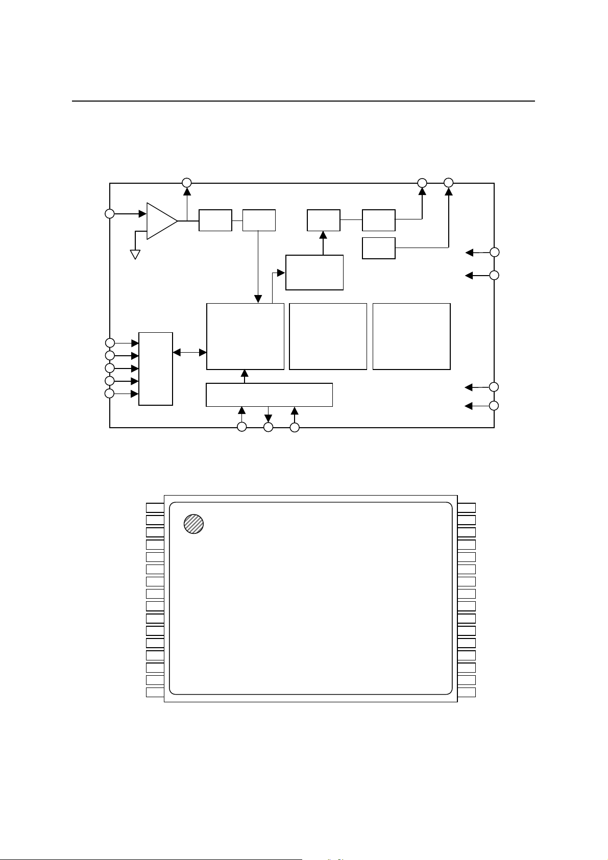
BLOCK DIAGRAM
PEDS87V1021-01
MS87V1021
LIN
CS
SI
SO
SK
BUSY
SG
MCU
I/F
LOUT
LPF
ADPCM
Analizer/
Synthesizer
Timing Controller
XT XT RESET
ADC
DAC
Volume
Controller
DARM
2M-Bit
LPF
SG
AOUT
MaskROM
512k-Bit
SG
AIN
AMON
TEST
TEST
PIN CONFIGURATION (TOP VIEW)
TEST
TEST
TEST
TEST
TEST
TEST
TEST
TEST
TEST
BUSY
SK
SO
SI
CS
MVDD
1
2
3
4
5
6
7
8
9
10
11
12
13
14
15
16
32-pin plastic TSOP Type I (TSOP32-P814-K)
MGND
32
AGND
31
SG
30
LIN
29
LOUT
28
AMON
27
AOUT
26
AIN
25
AVDD
24
DGND
23
TEST
TEST
22
21
TEST
20
RESET
19
XT
18
XT
17
DVDD
4/63
Page 5
1
Semiconductor
PIN DESCRIPTION
Pin No. Symbol I/O Description
14 SI I Inputs 8-bit command or data.
13 SO O Outputs 8-bit status or data.
12 SK I Data transfer clock for SI and SO.
15 CS I
11 BUSY O
19
18
20 RESET I
31 SG O
30 LIN I
29 LOUT O Output pin for internal OP amplifier
27 AOUT O
2
3-10,
21-23
28 AMON O Output pin for analog testing. Leave it unconnected.
26 AIN I Input pin for analog testing. Fix it at the GND level.
17 DVDD —
24 DGND — Digital GND pin
16 MVDD —
1 MGND — Ground pin for DRAM
25 AVDD —
32 AGND — Analog GND pin
XT
XT
TEST
TEST
The SK pulse is accepted w hen this pin i s “L”. The SK pulse is not accep ted when
this pin is “H”.
Outputs “H” level during command execution. At that time, do not input a
command from the external microcontroller.
Crystal oscillator connection pin s. When using an ex ternal cl oc k, input the clo ck
I
via the XT pin and le ave the XT pin unconn ected. When an external clock is u sed
O
in power down mode, fix the XT pin at the GND level.
The device is reset when “L” level is input. When oscillation starts, set this pin to
“L” level until oscillation becomes stable, and set to “H” level after oscillation
becomes stable. Data stored in the internal DRAM is cleared when “L” level is
input, while data is not erased when a reset signal is input for the purpose of
releasing the Pdwn1 mode.
Analog reference voltage (signal ground). Connect a 1 µF capacitor between
AGND and this pin.
Inverting input pin for internal OP amplifier. The non-inverting input pin is
internally connected to SG.
Output pin for playback LPF. This pin outputs playback waveforms and is
connected to the speaker driving amplifier.
Testing pin. The TEST pin is fixed at the V
I
the GND level.
Digital power supply pin. Connect a 0.1 µF or more bypass capacitor between
DGND and this pin.
Power supply pin for DRM. Connect a 0.1 µF or more by pas s c apa citor between
MGND and this pin.
Analog power supply pin. Connect a 0.1 µF or more bypass capacitor between
AGND and this pin.
DD
PEDS87V1021-01
MS87V1021
level and the TEST pins are fixed at
5/63
Page 6
1
Semiconductor
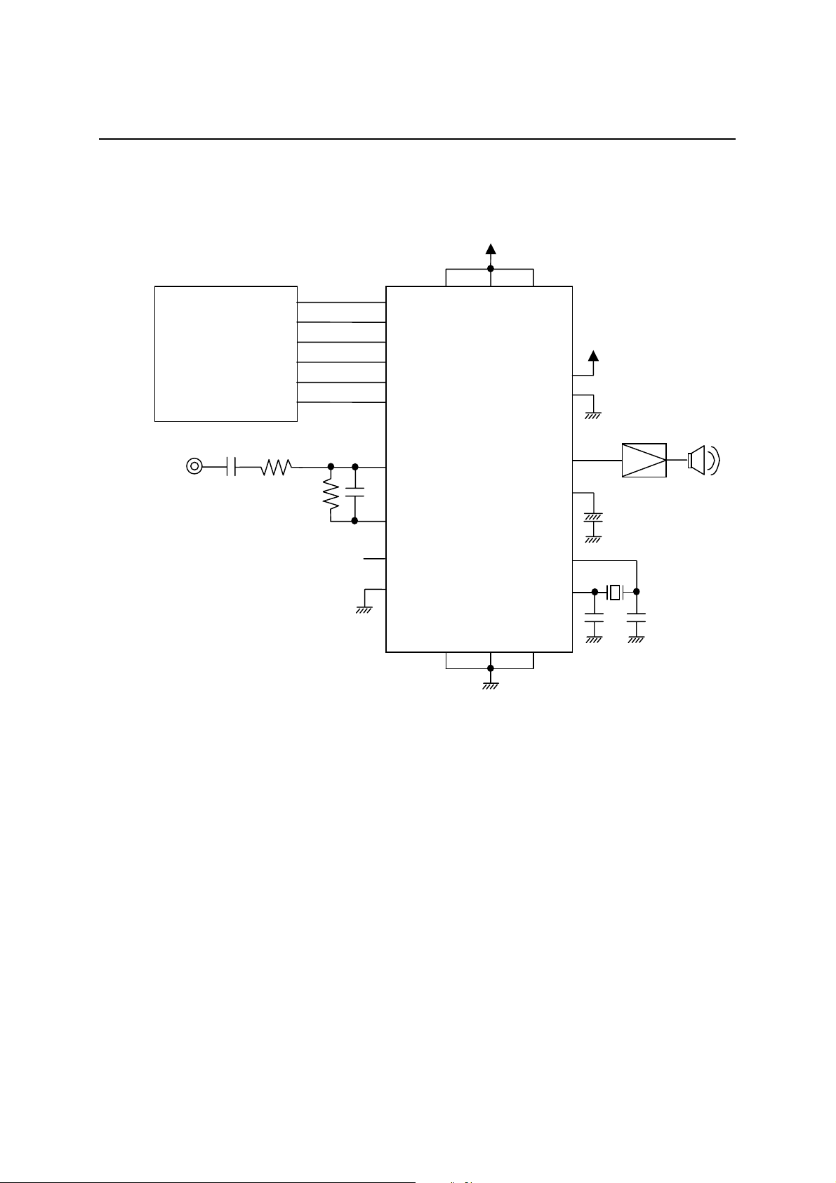
APPLICATION CIRCUIT EXAMPLE
MCU
MVDD DVDD AVDD
SI
SO
SK
CS
RESET
BUSY
PEDS87V1021-01
MS87V1021
TEST
TEST
Voice input
OPEN
MS87V1021
LIN
LOUT
AMON
AIN
MGND DGND AGND
MSC1157
AOUT
SG
XT
XT
6/63
Page 7
1
Semiconductor
ABSOLUTE MAXIMUM RATINGS
Parameter Symbol Condition Rated value Unit
Power supply voltage V
Pin voltage V
Output shortcircuit current I
Power dissipation P
Operating temperature T
Storage temperature T
DD
T
OS
D
OPR
STG
Ta = 25°C –0.5 to 4.6 V
Ta = 25°C –0.5 to VDD+0.5 V
Ta = 25°C 50 mA
Ta = 25°C 1 W
— –20 to +70 °C
— –55 to +150 °C
RECOMMENDED OPERATING CONDITIONS
(Ta= –20 to +70°C)
Parameter Symbol Min. Max. Unit
Power supply voltage V
DD
Power supply voltage GND 0 0 V
“H” input voltage V
“L” input voltage V
Source oscillation frequency f
IH
IL
OSC
2.7 3.6 V
VDD–0.2 V
DD
–0.2 0.2 V
4.096 MHz
PEDS87V1021-01
MS87V1021
(GND = 0 V)
V
ELECTRICAL CHARACTERISTICS
DC Characteristics
Parameter Symbol Condition Min. Typ. Max. Unit
“H” output voltage V
“L” output voltage V
Input leakage current
(Note 1)
Input leakage current
(Note 2)
Operating current I
Standby current 1 I
Standby current 2 I
OH
OL
I
LI1
I
LI2
DD
DDS
DDS2
Non-measured pins are at 0 V.
Non-measured pins are at 0 V.
When powered down, no load,
When powered down, no load,
Notes: 1. Applicable to input pins excluding XT and XT.
2. Applicable to XT and XT.
IOH = –1 mA VDD–0.3 — — V
IOL = +1 mA — — 0.3 V
0 V < VIN < V
0V < VIN < V
f
= 4.096 MHz no load — 10 15 mA
OSC
with DRAM refreshing
without DRAM refreshing
(Ta = –20 to +70°C)
DD
DD
–10 — 10 µA
–20 — 20 µA
——70µA
——40µA
7/63
Page 8
1
Semiconductor
AC Characteristics
1. Microcontroller interface mode
Parameter Symbol Min. Typ. Max. Unit Note
RESET pulse width t
RESET execution time t
Setup and hold time of SK for CS t
SK pulse width “H” t
SK pulse width “L” t
Setup time of SI for SK rise t
Hold time of SI for SK rise t
Data valid time from fall of CS t
Data Hi-Z time from rise of CS t
Data valid time from fall of SK t
BUSY rise time from rise of CS t
Source oscillation duty cycle t
RST
REX
SKS
SKH
SKL
DS
DH
CSE
CSF
DD
BSY
DUTY
PEDS87V1021-01
MS87V1021
(VDD = 2.7 to 3.6 V, Ta = –20° to +70°C)
(f
= 4.096 MHz Fsam = 8.0 kHz)
OSC
1——µs1
——5ms
500 — — ns
1000 — — ns
1000 — — ns
250 — — ns
250 — — ns
— — 200 ns
— — 200 ns
— — 200 ns
— — 200 ns
40 50 60 %
2. BUSY time when a command is executed
Parameter Symbol Min. Max. Unit Note
BUSY time after input of command t
BUSY time after input of mode setting command t
BUSY time after input of Area1 command
(3)
BUSY time after input of Area2 command
(3)
BUSY time after input of Delay command (3)
BUSY time after input of Rec command (2)
During
BUSY time after input of
recording
Play command (2)
During pause
Normal mode t
Delayed play mode
Retroactive play mode
Normal mode
Retroactive play mode
Normal mode
Delayed play mode — 65 ms 2
Retroactive play mode
Normal mode
Delayed play mode
Retroactive play mode
Delayed play mode
Retroactive play mode
Normal mode
(VDD = 2.7 to 3.6 V, Ta = –20 to +70°C)
(f
= 4.096 MHz Fsam = 8.0 kHz)
OSC
BR
MODB
AR1B
t
AR2B
t
DLYB
t
RECB
t
PLYB
t
PLYB
— 300 µs
— 300 µs
—1ms
—1ms
—1ms
—1ms
—65ms2
—1ms
8/63
Page 9
1
Semiconductor
Parameter Symbol Min. Max. Unit Note
During
BUSY time after input of Play2
command (2)
recording
During
pause
Retroactive
play mode
Normal mode
BUSY time after input of Stop
command
After input of Stop command
during pause
During ROM playback
(Non-linear)
BUSY time after input of Pause command t
Retroactive
BUSY time after input of Adrrd command (2)
play mode
Normal mode — 1 ms
BUSY time after input of Adrrd command (8)
BUSY time after input of Adrwr command (8) t
BUSY time after input of Cue/Rew command (2) t
BUSY time after input of Del command (2) t
BUSY time after input of Dtrw command t
BUSY time after input of Bytew command t
BUSY time after input of Byter command t
BUSY time after input of End command t
BUSY time after input of Copy command (7) t
BUSY time after input of Vol command t
BUSY time after input of Rply command t
BUSY time after input of Status command t
BUSY time after input of Nop command t
PEDS87V1021-01
MS87V1021
(VDD = 2.7 to 3.6 V, Ta = –20 to +70°C)
(f
= 4.096 MHz Fsam = 8.0 kHz)
OSC
t
PLAYB
t
SPB
t
ADRB
ADWB
CRB
DELB
CPYB
PB
BR
BR
BR
BR
BR
BR
BR
BR
—65ms2
—1ms
—65ms2
—1ms
—65ms2
—300µs
—1ms
—1ms
—65ms2
—65ms2
—300µs
—300µs
—300µs
—300µs
—10ms
1 page
—300µs
—300µs
—300µs
—300µs
A number in parenthesis indicates the number of bytes of each command.
9/63
Page 10
1
Semiconductor
3. Status flag time when a co mmand is executed
Parameter Symbol Min. Max. Unit Note
PEDS87V1021-01
MS87V1021
(VDD = 2.7 to 3.6 V, Ta = –20 to +70°C)
= 4.096 MHz Fsam = 8.0 kHz)
(f
OSC
Rec command to RPM bit set t
Play command to RPM bit set t
During ROM playback t
Play2 command to RPM bit set t
Stop command to RPM bit set t
During ROM playback t
STOP command (during pause) to RPM bit set t
Rec command to REC bit set t
RECR
PLYR
RPLYR
PLYR
SPR
RSPR
PSPR
REC
—1ms
—1ms
—2ms
—65ms2
—2ms
—1ms
—1ms
—1ms
Play command to PLY bit set Delayed play mode
During
recording
Retroactive play mode
t
PLY
—65ms2
During pausing
—1ms
Normal mode
Pause command to PAUSE bit set t
Pause command to PAUSE bit reset t
Address control time during repeated ROM playback t
PUS
PUSR
AD
—65ms2
— 300 µs
—2ms
Oscillation stop from rise of CS after input of Pwdn1 command — 65 ms
During ROM playback — 1 ms
t
Oscillation stop from rise of CS after input of Pwdn2 command — 65 ms
During ROM playback
PXT
—1ms
Note 1: When powering on or releasing the power down mode, input “L” level to the RESET pin until
crystal oscillation becomes stable. Moreover, when powering on, input again “L” level to the
RESET pin for more than t
to initialize the internal circuit.
RST
2: Depending on sampling frequency Fsam.
10/63
Page 11
PEDS87V1021-01
1
Semiconductor
MS87V1021
Analog Characteristics
(V
= 2.7 to 3.6V,Ta = -20 to +70°C)
DD
Parameter Symbol Condition Min. Max. Unit
DA output relative error |V
LPF input voltage range V
OP-amp open loop gain G
OP-amp input impedance R
OP-amp load resistance R
AOUT load resistance R
|No load — 5mV
DAE
FIN
OP
INA
OUTA
AOUT
—1/4 × V
DD
fIN = 0 to 4 kHz 10 dB
—1—MΩ
— 100 — kΩ
— 100 — kΩ
3/4 × V
DD
V
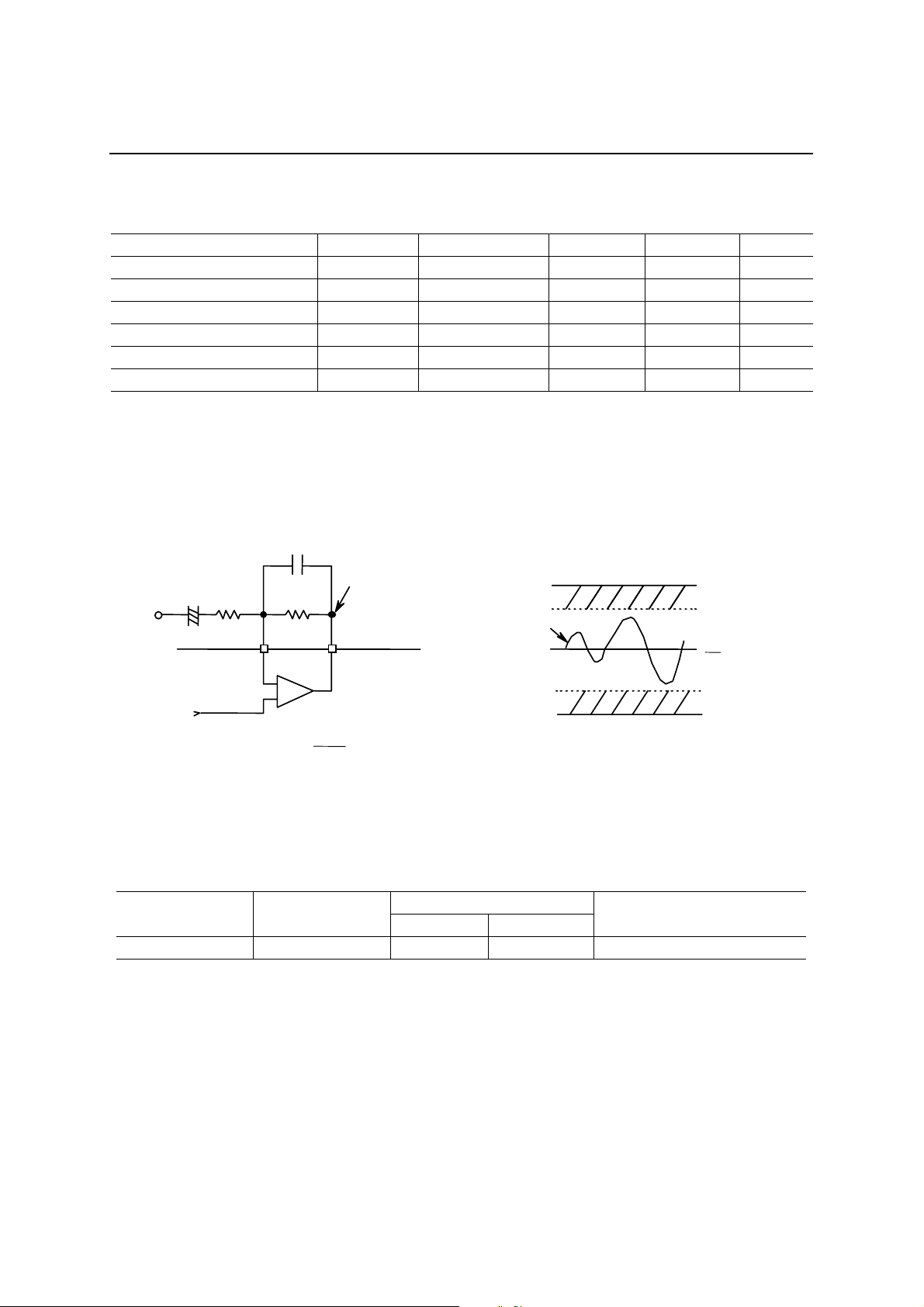
Analog Input Amplifier Ciricuit
This IC contains an OP a mpl ifier with the inverti ng input pin and output pin.
The analog circuit reference voltage (signal ground) is internally input as the non-inverting input. When
amplification is required, adjust the amplification factor using an external resistor after constructing the inverting
amplifier circuit.
V
DD
V
FIN (max)
1
V
2
V
FIN (min)
GND
DD
V
IN
SG
+
Inside LSI
LIN
V
V
LO
R2R1
V
LOUT
LO
+
R2
R1
V
IH
=
LO
The output pin, LOUT, of OP amplifier is internally input to LPF (Low Pass Filter). Adjust the gain using the
external resistor so that the V
is within the accessible input voltage range V
LO
. If VLO is over the V
FIN
, the LPF
FIN
output waveform will be distorted.
The example of SCF input voltage range is shown below.
Model Supply voltage V
MS87V1021 3 V 0.75 V 2.25 V 1.5 Vp-p
SCF admissible voltage range
DD
Min. Max.
SCF admissible input voltage
The minimum value of OP-amp load resistance is 100 kΩ. The feedback resistance R2 of inverting amplifier
circuit must be larger than 100 kΩ.
11/63
Page 12
PEDS87V1021-01
1
Semiconductor
MS87V1021
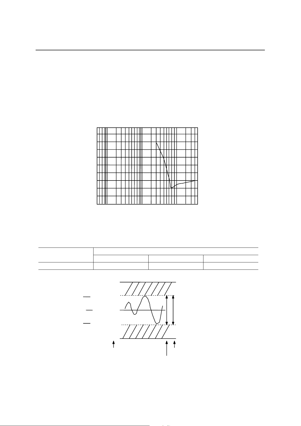
LPF Characteristics
The MS87V1021 contains a 4-th order LPF in which the switched capacitor filter technique is adopted. The LOUT
pin is internally connected to the input of LPF.
The attenuation rate is –40 dB/oct. The cut-off frequency and frequency characteristics vary in proportion to
sampling fre quency (Fsam).
The cut-off frequency is designed to 4/10 of sampling frequency.
The characteristics of LPF when Fsam = 8 kHz are shown below.
[dB]
20
10
0
–10
–20
–30
–40
–50
–60
–70
–80
100 1k 10k
[Hz]
AD, DA Converter Full Scale
Model
MS87V1021 1/4 × V
3
V
DD
4
1
V
2
1
V
4
LPF characteristics (Fsam = 8.0 kHz)
AD, DA converter full scale
Min. (V) Max. (V) Amplitude (Vp-p)
DD
(3 V)
V
DD
(2.25 V)
(1.5 V)
DD
(0.75 V)
DD
0 V (0 V)
A value in parenthesis
indicates a voltage when
is 3.0 V.
V
DD
LPF admissible input voltage range
3/4 × V
DD
AD, DA converter full scale
1/2 × V
DD
12/63
Page 13
PEDS87V1021-01
1
Semiconductor
MS87V1021
NOTICE
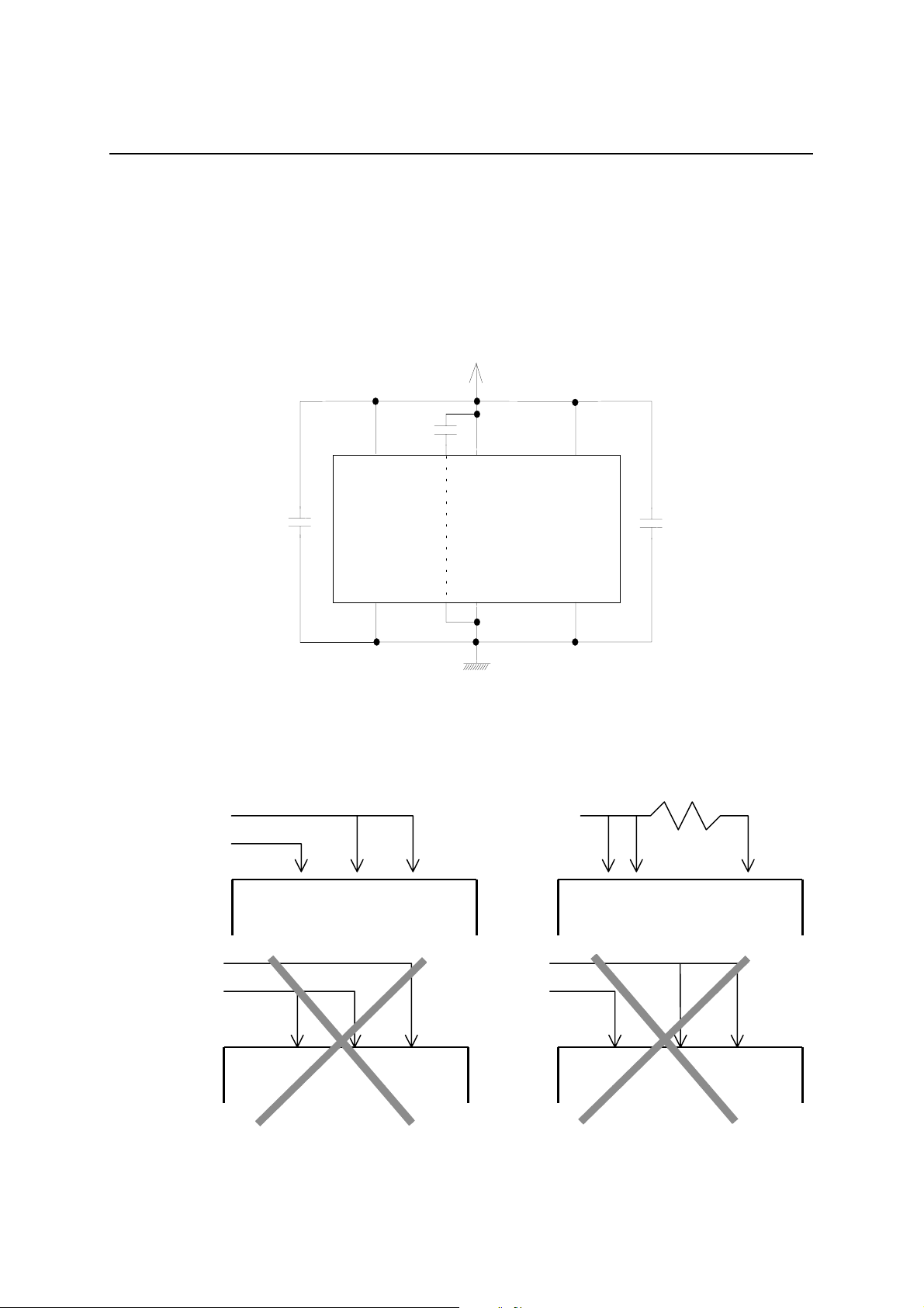
Power Supply Connection
The power of this IC is supplied from a single power supply as shown below, which should be connected to the
analog section, logic section and memory section separately.
Power source
DD
MV
MGND
DD
AV
AGND
Ground
DD
DV
DGND
If the analog section, digital section and memory section are supplied from different power sources, a latch-up may
occur. Be sure to avoid the power supply connections shown below.
Power source 1
Power source 2
LSI
AVDD
MVDD
DVDD
Power source
LSI
DVDD
MVDD
AVDD
Power source 1
Power source 2
LSI
AVDD
MVDD
DVDD
Power source 1
Power source 2
LSI
MVDD
DVDD
AVDD
13/63
Page 14
PEDS87V1021-01
1
Semiconductor
MS87V1021
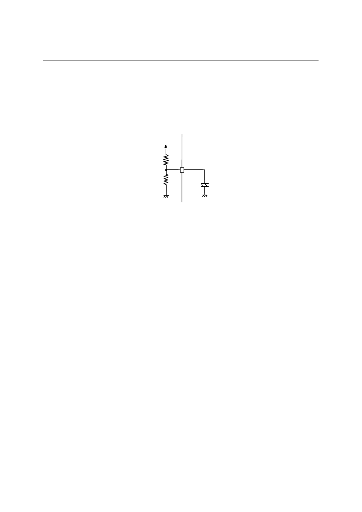
Supplementary Explanation on SG Pin
Connect a 1 µF electrolytic capacitor between the SG pin and AGND.
After reset or releasing the power down mode, do recording or playback after the voltage l evel of SG pi n becom e s
stable. The voltage level becomes stable at 1/2 of V
. The time to be stabilized is approximately 50 ms in case
DD
shown below.
Inside of LSI
Approx. 20 kΩ
Approx. 20 kΩ
External circuit
SG pin
+
1 µF
AGND
14/63
Page 15
1
Semiconductor
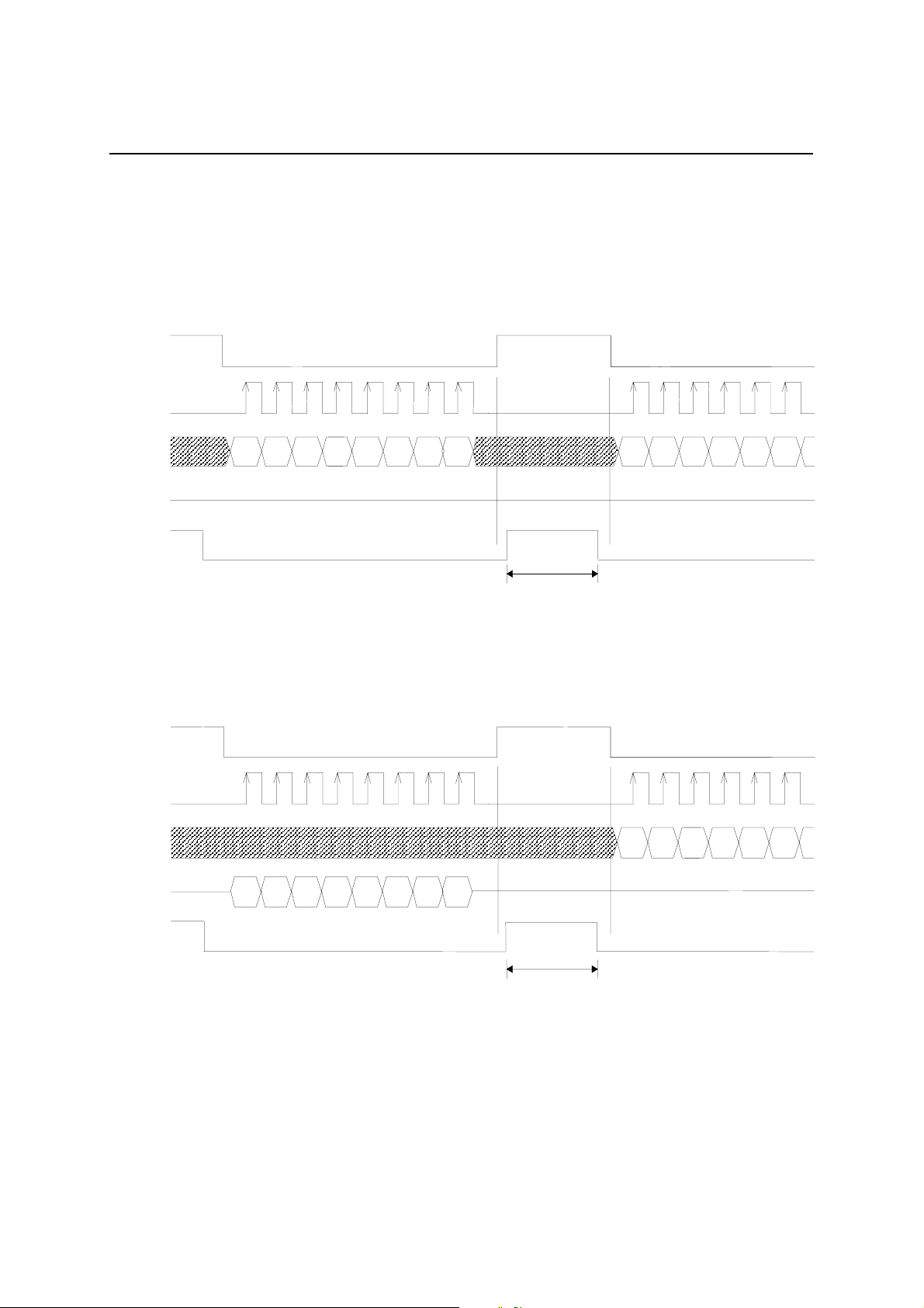
TIMING DIAGRAMS
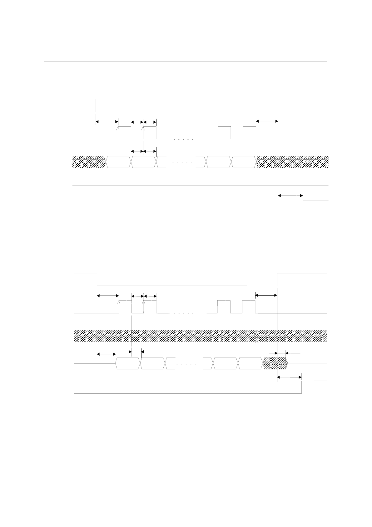
Serial microcontroller interface mode
[Data write operation]
PEDS87V1021-01
MS87V1021
CS (I)
SK (I)
SI (I)
SO (O)
BUSY (O)
[Data read operation]
CS (I)
SK (I)
MSB
1st byte
D6 D5 D4
Data output
D3
Hi-Z
D2
D1
LSB
Data I/O disabled
MSB
D6
2nd byte
D5
D4
Data input
D3 D2
SI (I)
SO (O)
BUSY (O)
Hi-Z
Q6 Q5 Q4 Q3 Q2 Q1
MSB
LSB
Data I/O disabled
MSB
D6 D5 D4 D3 D2
Hi-Z
15/63
Page 16
1
Semiconductor
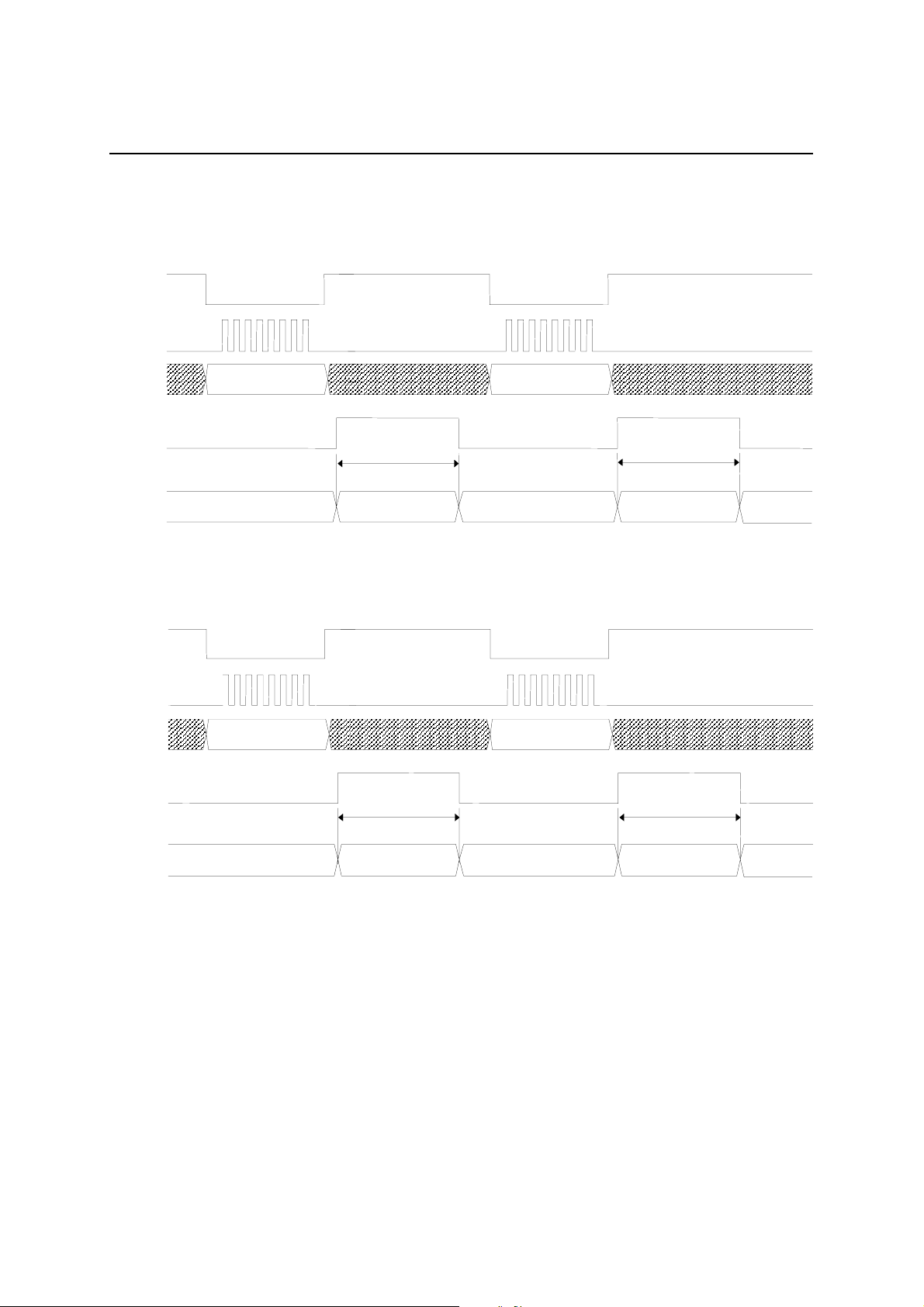
[Data write operation]
CS (I)
t
SKS
t
SKLtSKH
t
PEDS87V1021-01
MS87V1021
SKS
SK (I)
(Note) “L” level
t
t
DS
DH
SI (I)
MS
D6
SO (O)
BUSY (O)
(Note) Be sure to set SK to “L” when CS is at “H” level.
[Data read operation]
CS (I)
t
t
SKL
SKH
SK (I)
t
SKS
(Note) “L” level
Hi-Z
D1 LSB
t
SKS
(Note) “L” level
t
BSY
(Note) “L” level
SI (I)
t
DD
Q6
SO (O)
Hi-Z
t
CSE
MS
BUSY (O)
(Note) Be sure to set SK to “L” when CS is at “H” level.
D1 LSB
t
BSY
t
CSF
Hi-Z
16/63
Page 17
1
(2)
S
Semiconductor
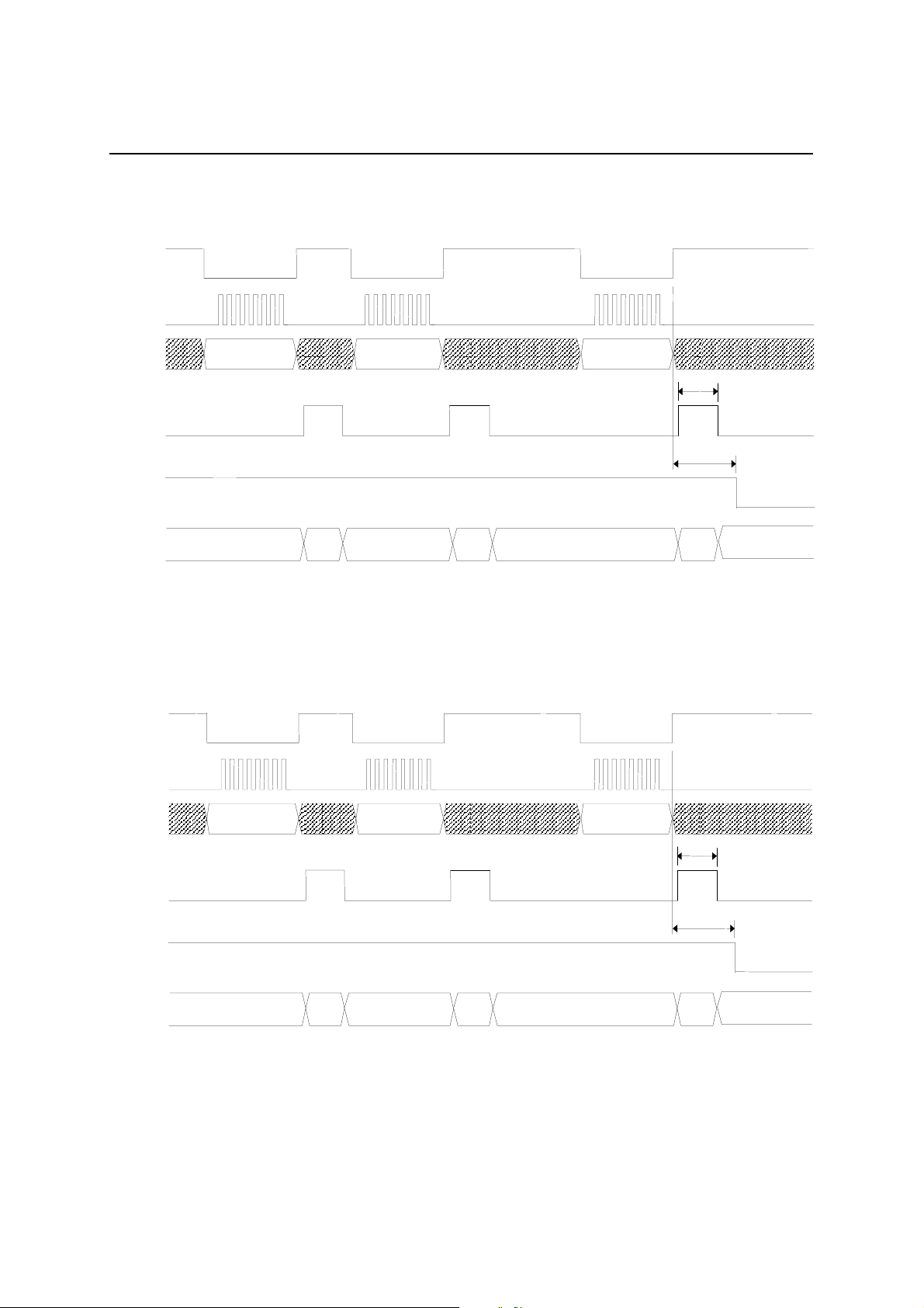
Ready for recording with Rec command
CS
SK
PEDS87V1021-01
MS87V1021
SI
Rec command (1) Rec command (2)
BUSY
Standby
Executing Rec
command (1)
Ready for playback with Play command
C
SK
SI
BUSY
Play command (1) Play command (2)
t
t
BR
Standby
t
BR
RECB
Executing Rec
command
t
PLYB
Standby
Standby
Executing Play
command (1)
Standby
Executing Play
command (2)
Standby
17/63
Page 18
1
(2)
Semiconductor
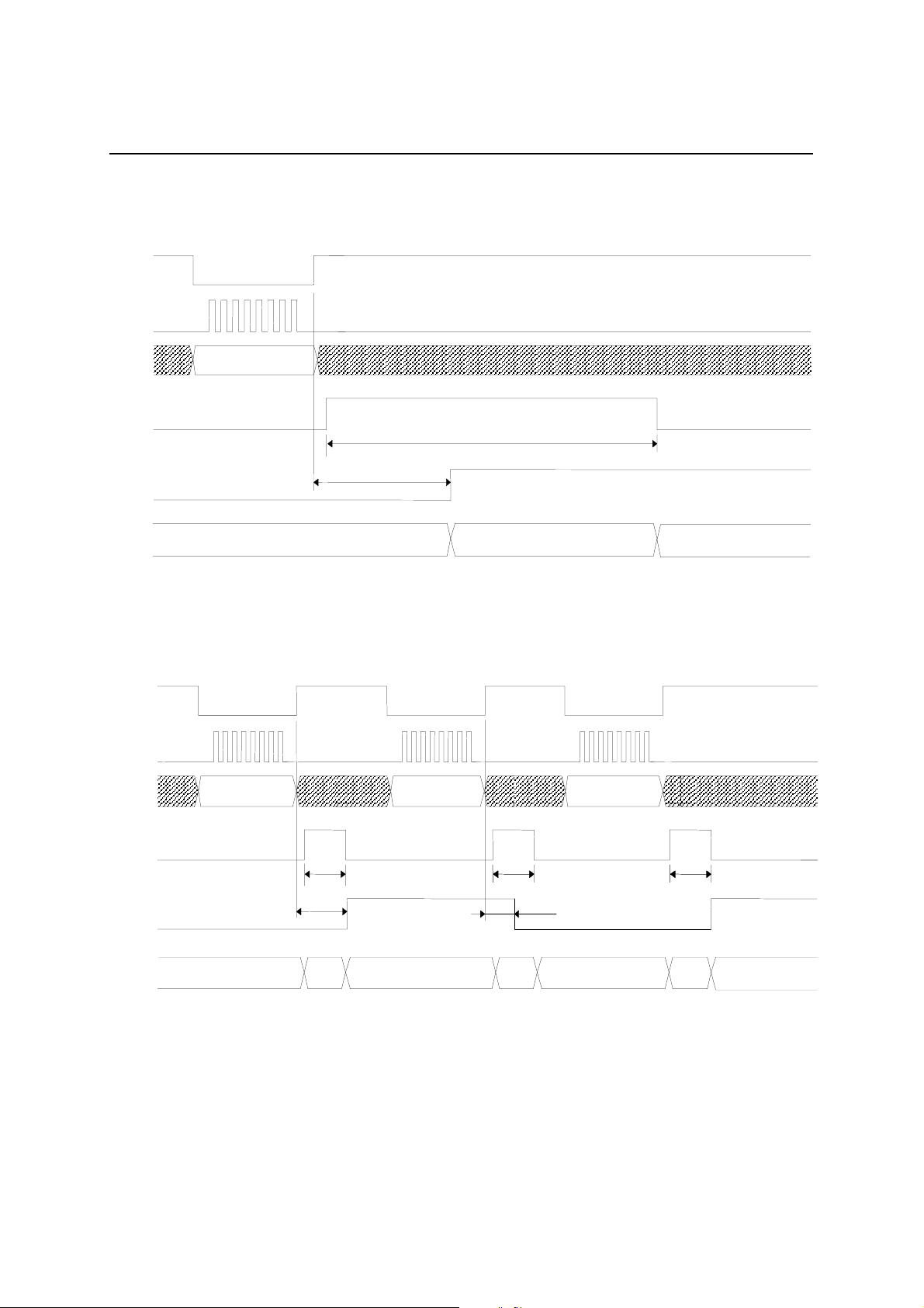
Starting recording with Start command
CS
SK
PEDS87V1021-01
MS87V1021
SI
Rec command
(1)
BUSY
RPM bit
Standby
Executing Rec
command (1)
Starting playback with Start command
CS
SK
Rec command
Standby
Executing Rec
command (2)
Start command
Standby
t
STB
t
RECR
Recording
Executing Start
command
BUSY
RPM bit
SI
Play command
(1)
Standby
Play command
Executing Play
command (1)
(2)
Standby Playing
Executing Play
command (2)
Start command
Standby
t
BR
t
PLYR
Executing Start
command
18/63
Page 19
1
S
Semiconductor
Ending recording/playback with Stop command
C
SK
PEDS87V1021-01
MS87V1021
SI
Stop command (1)
BUSY
t
SPR
RPM bit
Recording/playing Stop processing
Pause of recording/playback with Pause command
CS
SK
SI
Pause command
Pause command Pause command
t
SPB
Standby
BUSY
PAUSE
bit
Recording/playing
t
PB
t
PUS
Executing Pause
command
t
PB
t
PUSR
Pausing Pausing
Recording/playing
Executing Pause
command
t
PB
Executing Pause
command
19/63
Page 20

1
S
(1)
(2)
(3)
(1)
Semiconductor
Setting voice area block with Area1 command
CS
SK
PEDS87V1021-01
MS87V1021
SI
Area1
command
BUSY
t
BR
Standby
Executing Area1
command (1)
Setting voice area with Area2 command
C
SK
SI
BUSY
Area2
command
t
BR
Area1
command (2)
t
BR
Standby Standby
Executing Area1
command (2)
Area2
command
t
BR
Area1
command (3)
Standby
Area2
command
t
AR1B
Executing Area1
command (3)
t
AR2B
Standby
Executing Area2
command (1)
Standby Standby
Executing Area2
command (2)
Standby
Executing Area2
command (3)
20/63
Page 21

1
S
(1)
(1)
S
Semiconductor
Setting Delay value with Delay command
C
SK
PEDS87V1021-01
MS87V1021
SI
Delay
command
BUSY
t
BR
Standby
Executing Delay
command (1)
Deleting phrase with Del command
C
SK
SI
BUSY
Del command (1) Del command (2)
Delay
command (2)
t
BR
Standby Standby
Executing Delay
command (2)
t
BR
Delay
command (3)
Standby
t
DLYB
Executing Delay
command (3)
t
DELB
Standby
Executing Del
command
Standby
Executing Del
command (2)
Standby
21/63
Page 22

1
S
Semiconductor
Outputting STATUS with Stat us command
C
SK
PEDS87V1021-01
MS87V1021
SI
SO
BUSY
Status command
Standby
t
BR
Executing Status
command
Status output
Status output
t
BR
Standby
22/63
Page 23

1
S
command
Semiconductor
Reading recording/playback start address with Adrrd command
C
SK
PEDS87V1021-01
MS87V1021
SI
SO
Adrrd(1) Adrrd(2)
t
BR
t
ADRB
Stadr
[23:16]
Stadr
[15:8]
t
BR
Stadr
[7:0]
t
BR
BUSY
Standby
Standby Standby
Executing
Adrrd (1)
command
Executing
Adrrd (2)
command
Standby Standby Standby Standby Standby
Executing
Adrrd (3)
command
Executing
Adrrd (4)
command
Executing
command
Reading Stadr address Reading Enadr address
Writing recording/playback start address with Adrwr command
CS
SK
t
BR
Adrrd (5)
Enadr
[23:16]
Enadr
t
BR
Executing
Adrrd (6)
command
[15:8]
t
BR
Executing
Adrrd (7)
command
Enadr
[7:0]
t
ADRB
Standby
Executing
Adrrd (8)
SI
BUSY
Adrwr(1)
Standby
Adrwr(2)
t
BR
Standby Standby
Executing
Adrwr (1)
command
t
BR
Executing
Adrwr (2)
command
Stadr
[23:16]
Stadr
[15:8]
t
BR
Standby Standby Standby Standby Standby Standby
Executing
Adrwr (3)
command
Stadr
t
BR
Executing
Adrwr (4)
command
[7:0]
t
BR
Executing
Adrwr (5)
command
Enadr
[23:16]
Enadr
t
BR
Executing
Adrwr (6)
command
[15:8]
Writing Stadr address Writing Enadr address
Enadr
t
BR
Executing
Adrwr (7)
command
[7:0]
t
ADRB
Executing
Adrwr (8)
command
23/63
Page 24

1
S
S
(2)
(1)
(2)
Semiconductor
Copying page data with Copy command
C
SK
PEDS87V1021-01
MS87V1021
t
BR
PgStart
[7:0]
t
BR
SI
Copy(1)
t
PgStart
[15:8]
BR
BUSY
Standby
Standby Standby
Executing
Copy (1)
command
Executing
Copy (2)
command
Executing
Copy (3)
command
Fast forward/rewind with Cue/Rew command
C
SK
SI
Cue/
Rew(1)
Cue/
Rew
t
BR
t
CRB
PgEnd
[15:8]
Standby Standby Standby Standby Standby
t
BR
Executing
Copy (4)
command
Rew
PgEnd
[7:0]
Cue/
Target
t
BR
Executing
Copy (5)
command
Rew
t
BR
[15:8]
Cue/
t
BR
Executing
Copy (6)
command
t
CRB
Target
[7:0]
t
CPYB
Executing
Copy (7)
command
BUSY
Fast forwarding/rewinding
(single speed)
Standby
Normal playing
Standby
Executing
Cue/Rew (1)
command
Executing
Cue/Rew (2)
command
Fast forwarding/rewinding (double speed)
Standby
Cue/Rew (1)
Standby Standby
Executing
command
Executing
Cue/Rew (2)
command
24/63
Page 25

1
S
Semiconductor
Data transfer with Dtrw command
CS
SK
PEDS87V1021-01
MS87V1021
SI
Dtrw(1) Dtrw(2)
Dtrw(3) Dtrw(4)
SO
t
BR
t
BR
BUSY
Executing Dtrw commandStandby
Ending Dtrw mode with End comman d
C
SK
SI
End command
Bytew(1)
t
BR
t
BR
Executing Bytew
Write
Data
t
BR
command
t
BR
Byter(1)
t
Executing Byter
command
Read
Data
BR
t
BR
Standby
BUSY
Standby
t
BR
Executing End
command
Standby
25/63
Page 26

1
S
(1)
(1)
(2)
(1)
(2)
(2)
Semiconductor
Continuous ROM playback with Rply command
C
SK
PEDS87V1021-01
MS87V1021
SI
Rply
Rply
Phrase 1
t
BR
Rply
t
BR
Rply
Phrase 2
Rply
Rply
Phrase 3
BUSY
NAR bit
RPM bit
Voice
Playing phrase1
t
AD
Playing phrase2 Playing phrase3
t
AD
output
(Note)
When ROM is being continuously played, other commands than Rply command, Stop command, Vol
command and Status command cannot be acceptable.
26/63
Page 27

1
S
T
R
T
R
Semiconductor
Reset function
V
DD
ESET
BUSY
XT
X
Specified power
supply voltage
PEDS87V1021-01
MS87V1021
t
RST
t
REX
Stable oscillationOscillation start
[Reset after powering on]
When powering on, be sure to initialize the internal circuit by inputting an “L” level pulse to the RESET pin for a
specified time after the power supply voltage level reaches the specified level and oscillation becomes stable.
Power down function
C
SK
SI
ESET
BUSY
Power down
command
t
RST
t
REX
t
PXT
XT
X
Standby
Stable oscillation
Power down
command input
Power down command
processing
Oscillation stop
Power down
Oscillation
start
Oscillation start
RESET input
Stable oscillation
Executing
RESET
Standby
27/63
Page 28

PEDS87V1021-01
1
Semiconductor
MS87V1021
THE COMMANDS LIST
Delayed Play Mode
Command Code Description
Mode 1st Byte 01h Sets the operating mode to Delayed Play Mode.
Area2
Delay 1st Byte 38h Defines the Delay time (i.e. a time la g between recordi ng and its play back).
Rec
1st Byte 39h Selects a sound data area.
2nd Byte Start2[7:0] Start Block Address; address range: 00h to FFh, by default set to: 00h
3rd Byte End2[7:0] End Block Address; address range: 00h to FFh, by default set to: FFh
The memory area start ing from the block sp ecified with the S tart2 up t o that
specified with the End2 is selected. Up to 256 blocks can be selected.
Each value set with this command remains valid until you enter Reset or
the Mode command to change the operating mode.
You may not set the Start2 address value that is lower than the End2
address.
2nd Byte Dly[15:8]
The value for the Dly
3rd Byte Dly[7:0]
The Delay time can be obtained with the following formula:
(Dly × 250 ÷ Sampling Frequency)
For more details on sett ing the Dly value, see “Delay Time in Delayed Pl ay
Mode and Retroactive Play Mode” later in this document.
1st Byte 10h Sets the LSI to record-ready state and selects the Method and Samp
values.
2nd Byte
Method[7:4] The value for the Method.
Samp[3:0] The value for the Samp.
Entering the Start command following the Rec command input initiates
recording, which keeps going on until the Stop command is entered.
While recording, playback will not start until the Play command is entered.
If you enter the Rec command while recording and playing, the LSI stops
playing and outputs SG level from the AOUT pin. In this case, recording
still goes on even after playback stops.
Voice Synthesis Algorithm Sampling Frequency
Method
0h
Algorithm
ADPCM
1h ADPCM2
Others Prohibited
Play
1st Byte 20h Sets the LSI to play-ready state and s ele cts the Method and Samp values.
2nd Byte
Method[7:4] The value for the Method.
Samp[3:0] The value for the Samp.
Entering the Play comman d while recording caus es the LSI to start playing
what has been recorded the Delay time ago, with recording still going on.
For more details on the Method and Samp, see description on the Rec
command earlier in this document.
Start 1st Byte 30h Starts recording/playing.
Stop 1st Byte 40h Stops recording/playing.
Samp
3h 4.0kHz (fosc/1024)
4h 4.0kHz (fosc/1024)
5h 5.3kHz (fosc/768)
6h 6.4kHz (fosc/640)
7h 8.0kHz (fosc/512)
8h 8.0kHz (fosc/512)
9h 10.6kHz (fosc/384)
Others Prohibited
fosc = 4.096 MHz
Sampling Frequency
28/63
Page 29

1
Semiconductor
Retroactive Play Mode (1/2)
Command Code Description
Mode 1st Byte 02h
Area2
Delay
Rec
Play
Play2
1st Byte 39h Selects a sound data area.
2nd Byte Start2[7:0] Start Block Address; address range: 00h to FFh, by default set to: 00h
3rd Byte End2[7:0] End Block Address; address range: 00h to FFh, by default set to: FFh
1st Byte 38h Defines the Delay time (i.e. a time to go back to the past).
2nd Byte Dly[15:8]
3rd Byte Dly[7:0]
1st Byte 01h Sets the LSI to record-ready state and selects the Method and Samp
Method[7:4] The value for the Method.2nd Byte
Samp[3:0] The value for the Samp.
1st Byte 20h Sets the LSI to play-ready state and selects the Method and Samp
Method[7:4] The value for the Method.2nd Byte
Samp[3:0] The value for the Samp.
1st Byte 21h Sets the LSI to repeat-play-ready state and selects the Method and
2nd Byte
Method[7:4] The value for the Method.
Samp[3:0] The value for the Samp.
Sets the operating mode to Retroactive Play Mode. (Cue/Rewind
function available)
The memory area starting from the block specified with the Start2 up to
that specified with the End2 is selected. Up to 256 blocks can be
selected.
Each value set with this command r ema ins vali d until you enter Reset or
the Mode command to change the operating mode.
You may not set the Start2 address value that is lower than the End2
address.
The value for the Dly
Use this command to set the Delay time, that is the time length going
back to the past from the time when the Play or Play2 command is
entered.
The Delay time can be obtained with the following formula:
(Dly × 250 ÷ Sampling Frequency)
For more details on setting the Dly value, see “Delay Time in Delayed
Play Mode and Retroactive Play Mode” later in this document.
values.
For more details on the Method and Samp, see description on the Rec
command in Delayed Play Mode earlier in this document.
values.
Entering the Play command while recording causes the LSI to play on ce
from what was recorded the Delay tim e ago up to the tim e when the Pl ay
command is entered. In this case, recording stops.
For more details on setting the Dly value, see “Delay Time in Delayed
Play Mode and Retroactive Play Mode” later in this document.
Samp values.
Entering the Play2 command while recording causes the LSI to repeat
playing from what was recorded the Delay time ago up to the time when
the command is entered. In this case, recording stops.
For more details on setting the Dly value, see “Delay Time in Delayed
Play Mode and Retroactive Play Mode” later in this document.
PEDS87V1021-01
MS87V1021
29/63
Page 30

1
Semiconductor
Retroactive Play Mode (2/2)
Command Code Description
Adrrd
Adrwr
Stop 1st Byte 40h Stops recording or playing in Retroactive Play Mode.
1st Byte 51h
2nd Byte 00h Set this to “00h”.
3rd Byte Stadr[23:16](O)
4th Byte Stadr[15:8](O)
5th Byte Stadr[7:0](O)
6th Byte Enadr[23:16](O)
7th Byte Enadr[15:8](O)
8th Byte Enadr[7:0](O)
1st Byte 50h Use this command to write the Start and End address values of the
2nd Byte 00h Set this to “00h”.
3rd Byte Stadr[23:16]
4th Byte Stadr[15:8]
5th Byte Stadr[7:0]
6th Byte Enadr[23:16]
7th Byte Enadr[15:8]
8th Byte Enadr[7:0]
1st Byte 41h Pauses recording or playing.Pause
1st Byte 30h Starts recording or playing in Retroactive Play Mode.Start
Use this command to read the Start and End address values of the
recorded data.
Outputs the start-record address (in serial from the SO pin).
Outputs the end-record address (in serial from the SO pin).
You need to know the exact address where sound data is stored to play
the data again in Retroactive Play Mode after record/play operation in
the mode is complete. T his command allow s you to read the start-record
and end-record addresses.
playback data.
The value for the start-play address. You need to set the lower 7 bits to
“0”.
The value for the end-play address. You need to set the lower 7 bits to
“1”.
You need to specify the address where sound data is stored to play the
data again in Retroactive Play Mode after record/play operation in the
mode is complete. This command enables you to write the start-play
and end-play addresses. Normally you specify the addresses that you
read by using the Adrrd command.
Re-entering the command resets pause state and resumes the earlier
operation.
Entering the Start command foll owing the Rec co mmand cause s the LSI
to start recording in Retroactive Play mode. Meanwhile, entering the
Start command following th e Play 1 or Pl ay2 co mmand causes the LSI to
start playing, looking up address informatio n on the internal Stadr /Enadr
register that contains the record-start and record-end addresses.
PEDS87V1021-01
MS87V1021
30/63
Page 31

1
Semiconductor
Normal Mode (1/2)
Command Code Description
Mode 1st Byte 03h
Area1
Area2
Rec
Play
Play2
1st Byte 36h Selects an area for address control and sound data.
2nd Byte Start1[7:0] Start Block Address; address range: 00h to FFh, by default set to: 00h
3rd Byte End1[7:0] End Block Address; address range: 00h to FFh, by default set to: FFh
1st Byte 39h Selects a sound data area.
2nd Byte Start2[7:0] Start Block Address; address range: 00h to FFh, by default set to: 00h
3rd Byte End2[7:0] End Block Address; address range: 00h to FFh, by default set to: FFh
1st Byte 10h
2nd Byte
1st Byte 20h Sets the LSI to one-time-play-ready state and selects a phrase to be
2nd Byte Phrase[7:0] The value for the Phrase. Range: 01h to FFh
1st Byte 21h Sets the LSI to repeat-play-ready state and selects a phrase to be
2nd Byte Phrase[7:0] The value for the Phrase. Range: (01h to FFh)
Method[7:4] The value for the Method.
Samp[3:0] The value for the Samp.
Sets the operating mode to Normal Play Mode. (Cue/Rew function
available)
The memory area ranging from the block specified with the Start1 up to
that specified with the End1 is selected for storing both address control
and sound data. Up to 256 blocks can be selected.
Each value set with this command remains valid until you enter Reset.
The Area1 command is valid in Normal Play Mode only.
You may not set the Start1 address value that is lower than the End1
address.
This command is used to select a sound data area within the memory
area defined by using the Area1 command. The area ranging from the
block specified with the Start2 up to that specified with the End2 is
selected.
Each value set with this command r ema ins valid until you enter Reset or
the Mode command to change the operating mode.
The first 2 blocks (02h; 16 pages) of the memory area selected by the
Area1 command are automatically assigned to the Addres s Control Data
Area. Therefore, blocks you can actually s ele ct as Sound Data Area are
the third block and there after ( the val ue for th e Start 1 + 02h). T he v alues
defined by the Start1, Start2 and End1, End2 must satisfy the following
formula:
Start2 ≥ Start1 + 02h; End2 ≤ End1
For more details, see “Contr olli ng addr es ses in Normal Play Mode” later
in this document.
Note: You may not set the Start2 address value that is lower than the
End2 address.
Sets the LSI to record-ready state and selects the Method and Samp
values.
For more details on the Method and Samp, see description on the Rec
command in Delayed Play Mode earlier in this document.
played.
For playback the LSI use s the M ethod and Sa mp values set w ith the Rec
command.
played.
For playback the LSI use s the M ethod and Sa mp values set w ith the Rec
command.
PEDS87V1021-01
MS87V1021
31/63
Page 32

1
Semiconductor
Normal Mode (2/2)
Command Code Description
Adrrd
Adrwr
Del
Start 2nd Byte Phrase[7:0] Starts recording or playing.
Stop 1st Byte 40h Stops recording or playing.
1st Byte 51h
2nd Byte Phrase[7:0] The value for the Phrase. Range: 01h to FFh
3rd Byte
4th Byte
5th Byte
6th Byte
7th Byte
8th Byte
1st Byte 50h Use this command to write the Start and End address values of the
2nd Byte Phrase[7:0] The value for the Phrase. Range: 01h to FFh
3rd Byte
4th Byte
5th Byte
6th Byte
7th Byte
8th Byte
1st Byte 70h Deletes the specified phrase(s).
2nd Byte Phrase[7:0] The value for the Phrase. Range: 01h to FFh
1st Byte 41h Pauses recording or playing.Pause
Stadr[23:16](O)
Stadr[15:8] (O)
Stadr[7:0] (O)
Enadr[23:16](O)
Enadr[15:8](O)
Enadr[7:0](O)
Stadr[23:16]
Stadr[15:8]
Stadr[7:0]
Enadr[23:16]
Enadr[15:8]
Enadr[7:0]
Use this command to read the Start and End address values of the
specified phrase.
Outputs the Start Address (in serial from the SO pin).
Outputs the End Address (in serial from the SO pin).
This command all ows y ou to re ad th e Star t Addr ess and End A ddress of
the phrase specified.
specified phrase.
The value for the Start Address. You need to set the lower 7 bits to “0”.
The value for the End Address. You need to set the lower 7 bits to “1”.
With this command you can define a phrase and the Start and End
addresses of the phrase. Addressing is in Pages. You should specify
the page's top address (the lower 7 bits = 0) for the Start Address, while
the page's end address (the lower 7 bits = 1) for the End Address.
If you specify Stadr = Enadr, the LSI performs endless (loop) recording.
Note: You may not spe cify the Start a ddres s value that is lar ger than the
End address.
If you specify “00h” for the Phrase, all phrase data will be erased.
Re-entering the command resets pause state and resumes the earlier
operation.
PEDS87V1021-01
MS87V1021
32/63
Page 33

1
A
A
Semiconductor
Other Commands Common in All Modes (1 /2)
Command Code Description
Nop 1st Byte 00h Represents “No Operation”. The command is ignored.
Dtrw
Byter
End 1st Byte 63h Use this command to end Dtrw mode.
Pdwn1 1st Byte 80h Use this command to let the LSI enter power-down state.
Pdwn2 1st Byte 88h Use this command to let the LSI enter power-down state.
Test 1st Byte F0h The LSI test command. Do not enter the command.
Rply
Vol
1st Byte 60h Use this command to make an access to the on-chip DRAM or Mask
ROM.
2nd Byte
3rd Byte
4th Byte
Adr[23:16]
Adr[15:8]
Adr[7:0]
Specify the head address at which you want to start reading or writing.
You can’t access to DRA M and M ask ROM simult aneous ly. If y ou w ant to
access to the other memory address, you need to enter the End
command to end Dtrw mode once, and then set up the new address by
using the Dtrw command again.
1st Byte 61h Use this command to write data to the on-chip DRAM.Bytew
2nd Byte Data[7:0] Writing data.
After writing data is complete, the address pointer for writing is
incremented by one. When the last address of the DRAM is reached, the
next address automatically returns to the top address of the DRAM.
1st Byte 62h Use this command to read data from the on-die DRAM or Mask ROM.
2nd Byte Data[7:0] Reading data (in serial from the SO pin).
After reading data is complete, the address pointer for reading is
incremented by one. When the la st address of the DR AM or Mask ROM is
reached, the next address automatically returns to the top address of
each memory.
The on-chip DRAM enters self-refresh mode to preserve all the stored
data.
Data on the DRAM will be lost.
1st Byte 24h Use this command to play Mask ROM data.
2nd Byte Phrase[7:0] Sets ROM phrase value.
The Mask ROM Phrase values are independently controlled, separately
from the Phrase values for DRAM recording.
1st Byte 28h Use this command to set up a volume level.
2nd Byte Vol[7:0]
The default value for the Vol is “0h”.
Vol values and Attenuation
Vol
ttenuation
0h 0 dB 4h –12 dB
1h –3 dB 5h –15 dB
2h –6 dB 6h –18 dB
3h –9 dB 7h –21 dB
Vol
ttenuation
PEDS87V1021-01
MS87V1021
33/63
Page 34

1
—
—
—
Semiconductor
Other Commands Common in All Modes (2 /2)
Command Code Description
Copy
1st Byte 68h Use this command to move data in Pages.
2nd Byte
3rd Byte
4th Byte
5th Byte
PgStart[15:8]
PgStart[7:0]
PgEnd[15:8]
PgEnd[7:0]
Enter the top address of the page where the data you want to move is
stored.
Enter the last address of the page where the data you want to move is
stored.
PEDS87V1021-01
MS87V1021
6th Byte
7th Byte
Target [15:8]
Target [7:0]
Enter the top address of the starting page to which you want to move the
data.
The data from the page specified with the PgStart to the page specified
with the PgEnd is moved to the pages start ing from the page sp ecified w ith
the Target.
Status 1st Byte FFh Reads LSI’s status.
2nd Byte Status[7:0](O) Outputs the LSI’s status signals. (in serial from the SO pin)
Bit
7 PAUSE
6PLY
5REC
4RPM
3NAR
2
1
0
Status Bit Function
Name
Outputs “H” during pausing.
Outputs “H” during playing.
Outputs “H” during recording.
Outputs “L” while processing re cordin g or playing
data. Outputs "H" while the ADPCM unit is ready.
Outputs “H” when the LSI gets ready to accept the
next phrase data while pla ying Mask ROM data.
No function.
No function.
No function.
Description
34/63
Page 35

PEDS87V1021-01
—————
—
—
—
—
—————
—
——A
—
1
Semiconductor
MS87V1021
Fast Forward/Rewind Playback (Valid only in Retroactive Play mode and Normal Mode)
Command Code Description
Cue/Rew
Use this command, while playing, to start Fast Forward or Rewinding
1st Byte 23h Start fast forward or rewing playback
2nd Byte
Unit[7:4] Sets Unit value
Speed[3:0] Sets Speed value
playback from the point that is currently played. When you want to get the
speed back to normal X1 play, execute the Cue/Rew command again with
the Speed value of “0”. The Unit vlaue is ignored in this operation.
Unit Function
Unit Description
By unit of 1,024 bits
0
By unit of 2,0484 bits
1
By unit of 4,0964 bits
2
By unit of 8,192 bits
3
By unit of 16,384 bits
4
Speed Function
Speed Description Speed Description
0 FF at X1 speed 8
1
FF at X1.25 speed
2
FF at X1.5 speed
3
FF at X2 speed
4
FF at X3 speed
5
FF at X4 speed
Rewind at X1 speed
9
Rewind at X1.25 speed
A
Rewind at X1.5 speed
B
Rewind at X2 speed
C
Rewind at X3 speed
D
Rewind at X4 speed
Combinations of Units and Speeds
Speed
012345
Unit
0X1
1 X1.25
2X1.5
3X2
4X3
5X4
8X1
9 X1.25
X1.5
BX2
CX3
DX4
The combination of the Unit value and the Speed value affects playback
sound. Therefore, choose a proper combination of the two values
depending on the type of sound to be played. The Fast Forward/Rewind
Play function is available only in Retroactiv e Play M ode and Normal mo de.
If you use this function, you should not use the Block address FFh.
Note: The following restrictions apply to this function:
• The size of the sound data area must be 128 pages (i.e. 16 blocks) or
more.
• You may not use the block address FFh.
• The Cue/Rew command is unavailable for playback after an endless
recording session or repeat play by using the Play2 command.
35/63
Page 36

1
Semiconductor
FLOWCHARTS
Delayed Play Mode
PEDS87V1021-01
MS87V1021
Start
[Select operating
mode]
[Select voice area]
[Set Delay time]
[Set to recording state]
[Start recording]
N
[Start
playback]
N
Mode
command
Area2
command
Dly
command
Rec
command
Start
command
End ?
N
Play ?
Y
Play
command
Stop playing ?
Y
Rec
command
Send Mode command (01h)
Select Delay mode
Send Area2 command
Send Start2 [7:0]
Send End2 [7:0]
Send Dly command (38h)
Send Dly [15:8]
Send Dly [7:0]
Send Rec command (10h)
Send Method [7:4]/Samp [3:0]
Send Start command (30h)
Y
Send Play command (20h)
Send Method [7:4]/Samp [3:0]
(Note)
The play mode is maintained until
Stop command is input.
(Note)
When Play command is issued during
recording, the Method/Samp value of
Rec command has priority.
[Stop recording/playback]
Stop
command
End
Send Stop command (40h)
36/63
Page 37

PEDS87V1021-01
1
Semiconductor
MS87V1021
Retroactive Play Mode (1)
Shown below is the flowchart in which playback starts by issuing the Play or Play2 command during recording.
When playing the recorded voice, see the flowchart on the next page.
Start
[Select operating mode]
[Select voice area]
[Set Delay time]
[Set to recording status]
[Start recording]
[Start one time playback]
or
[Start repeat playback]
N
Mode
command
Area 2
command
Dly
command
Rec
command
Start
command
Play ?
Y
Play or Play2
command
Send Mode command (02h)
Select Retroactive play mode
Send Area2 command (39h)
Send Start2 [7:0]
Send End2 [7:0]
Send Dly command (38h)
Send Dly [15:8]
Send Dly [7:0]
Send Rec command (10h)
Send Method [7:4]/Samp [3:0]
Send Start command (30h)
Send Play command (20h) or Play2 command
(21h)
Send Method [7:4]/Samp [3:0] (Note)
Recording stops and repeat playback starts.
[Start playback after fast
forwarding/rewinding]
[Stop repeat playback]
Send Stop command (40h)
N
Cue or Rew ?
Y
Cue/Rew
command
End ?
Y
Stop
command
End
(Note)
When Play or Play2 command isissued during
N
recording, the Method/Samp value of Rec
command has priority.
Send Cue/Rew command (23h)
Send Unit [7:4]/Speed [3:0]
(Caution)
Note the following when playing the recorded voice in
Retroactive play mode after playback in other modes
such as Delayed play mode and Normal playb mode.
The recording address information on playback in
Retroactive play mode is not maintained when the
mode is moved to other mode. Therefore, be sure to
read the recording address information with Adrrd
command before moving to other mode. When doing
playback, write the recording address information as
the playback address information with Adrwr
command.
37/63
Page 38

PEDS87V1021-01
1
Semiconductor
MS87V1021
Retroactive Play Mode (2)
Shown below is the flowchart in which the voice that was recorded in Repeat playback mode is played later.
Start
[Select operation mode]
[Select voice area]
[Set Delay time]
[Read recording address
information]
[Write playback address
information]
[Set to one time playback
status]
or
[Set to repeat playback statu s]
Mode
command
Area2
command
Dly
command
Adrrd
command
Adrwr
command
Play or Play2
command
Send Mode command (02h)
Select Retroactive play mode
Send Area2 command (39h)
Send Start2 [7:0]
Send End2 [7:0]
Send Dly command (38h)
Send Dly [15:8]
Send Dly [7:0]
Send Adrrd command (51h)
Send (00h)
Receive Stadr [23:16], Stadr [15:8], Stadr [7:0]
Receive Enadr [23:16], Enadr [15:8], Enadr [7:0]
Send Adrrd command (50h)
Send (00h)
Send Stadr [23:16], Stadr [15:8], Stadr [7:0]
(Lower 7 bits Stadr [6:0] are “0”)
Send Enadr [23:16], Enadr [15:8], Enadr [7:0]
(Lower 7 bits Enadr [6:0] are “1”)
Send Play command (20h) or Play2 command (21h)
Send Method [7:4]/Samp [3:0]
[Start playback]
[Fast forwarding/
rewinding starts]
N
[Stop playback] Send Stop command (40h)
Start
command
Cue/Rew ?
Y
Cue/Rew
command
End ?
Y
Stop
command
End
Send Start command (30h)
N
Send Cue/Rew command (23h)
Send Unit [7:4]/Speed [3:0]
38/63
Page 39

1
Semiconductor
Recording in Normal Mode
PEDS87V1021-01
MS87V1021
Start
[Select operating mode]
[Select voice area block]
[Select voice area]
[Write record ing addr ess
information]
[Set to recording status]
[Start recording]
Mode
command
Area1
command
Area2
command
Adrwr
command
Rec
command
Start
command
Recording
finished ?
Send Mode command (03h)
Select Normal mode
Send Area1 command (36h)
Send Start1 [7:0]
Send End1 [7:0]
Send Area2 command (39h)
Send Start2 [7:0]
Send End2 [7:0]
Send Adrrd command (50h)
Send (00h)
Send Stadr [23:16], Stadr [15:8], Stadr [7:0]
(Lower 7 bits Stadr [6:0] are “0”)
Send Enadr [23:16], Enadr [15:8], Enadr [7:0]
(Lower 7 bits Enadr [6:0] are “1”)
Send Rec command (10h)
Send Method [7:4]/Samp [3:0]
Send Start command (30h)
RPM bit = “1”
Y
N
[End recording]
N RPM bit = “0”
End
recording ?
Y
Stop
command
End
Send Stop
command
(40h)
39/63
Page 40

1
Y
N
Semiconductor
Playback in Normal Mode
PEDS87V1021-01
MS87V1021
Start
[Select operating mode]
[Select voice area block]
[Select voice area]
[Set to playback status]
[Start playback]
Mode
command
Area1
command
Area2
command
Play
command
Start
command
Playback
finished ?
N RPM bit = “0”
End playback ?
Send Mode command (03h)
Select Normal mode
Send Area1 command (36h)
Send Start1 [7:0]
Send End1 [7:0]
Send Area2 command (39h)
Send Start2 [7:0]
Send End2 [7:0]
Send Play command (20h)
Send Phrase [7:0]
Send Start command (30h)
RPM bit = “1”
Y
[Start playback after fast
forwarding/rewinding]
[End playback]
N
N
Cue/Rew ?
Y
Cue/Rew
command
Stop
command
End
Send Cue/Rew command (23h)
Send Unit [7:4]/Speed [3:0]
Send Stop
command (40h)
40/63
Page 41

1
Semiconductor
Dtrw Command
PEDS87V1021-01
MS87V1021
Start
[Select operating
mode]
N
Dtrw
command
Continue Dtrw ?
Y
Write data ?
Y
Bytew
command
[Set the top address of DRAM or ROM to be accessed]
Send Dtrw command (60h)
Send Adr [23:16], Adr [15:8], Adr [7:0]
N
[Write data to DRAM]
Send Bytew command (61h)
Send Data [7:0]
Byter
command
[Read data from DRAM, ROM]
Send Byter command (62h)
Receive Data [7:0]
End
command
End
[End of access to DRAM, ROM]
Receive End command (63h)
41/63
Page 42

1
O
d
play
Semiconductor
STATUS TRANSITION DIAGRAM
Area1: Select a voice data management area (Normal
mode).
Area2: Select a voice data storage area.
Adrwr: Input a phrase recor d ing/ pl ayback address
(Retroactive m ode, Normal m ode).
Adrrd: Output a phrase recording/playback address
(Retroactive m ode, Normal m ode).
Mode: Select a mode.
Delay: Set to a Dly volume.
Rec: Set to a recording status.
Play: Set to a pla yback status.
Play2:Set to repeat-playready status.
Vol: Select a volume.
Del: Del ete phrase dat a.
Copy: Copy page data.
Status: Output a status signal.
Power down
Input RESET
pulse.
Byter: Start reading data
Pwdn1: Power do wn (data is
retained)
Pwdn2: Power do wn (data is not
retained)
Waiting for com man d
Dtrw : Read/write data
Byte data
reading
Reading/writing dat a
PEDS87V1021-01
MS87V1021
Byte data
writing
Bytew: Start writi ng dat a
End : End reading/writing data
Vol: Set a volum e
Status: Output a status
signal
Rec: Stop playback
(in Delayed play
mode)
Playback is pausing
Vol: Set a volum e
Status: Output a status signal
Stop: Stop
recording/playback
Mode=01h
peration in Delaye
play mode
Play: Re-start
back
Stop: Stop
recording/playback
Stop: Stop
recording/playback
Start: Start
recording/playback
Recording/playback in
each mode
Mode=02h
a
Operation in Retroact iv e
a
Mode=03h
Stop: Stop
recording/playback
Vol: Set a volum e
Status: Output a status
signal
play mode
Pausing
Pause: Pause/resume
Stop: Stop ROM
playback
Rply: Start ROM
playback
Continuous
phrase playback
Recording/playback in
Normal mode
a
Playback after Cue/ Re w
Stop: Stop playback
ROM playback
Cue/Rew: Fast
forwarding/rewinding
Pause: Pause/resume
a
Pausing
a
Rply: Start ROM
playback
Vol: Set a volum e
Status: Output a status
signal
Vol: Set a volum e
Status : Output a status signal
Pause: Pause/resume
Pausing
42/63
Page 43

PEDS87V1021-01
1
Semiconductor
MS87V1021
SUMMARY OF OPERATING MODES AND FUNCTIONS
Delayed Play Mode
Delayed Play is a unique operational mode that enables you to hear what has been recorded several seconds ago
while the LSI keeps on recording current sound. As shown in th e figure below, while the LSI keeps on recording in
endless circular motion by returning to the top address of the DRAM’s area specified with the Area2 command, it
simultaneously plays what has been recorded earlier with a time lag defined with the Delay command.
Adding this function to a conventional recording system like cassette tape recorder enables you to record sound in
the past to such other media as a cassette tape.
In Retroactive Play Mode or Normal Mode, you cannot play what has been recorded in Delayed Play Mode.
Returning to the top address of the area
Recording area on DRAM
Play
Record
Delay Time
(Time lag between
Recording and Playing)
43/63
Page 44

PEDS87V1021-01
p
p
1
Semiconductor
MS87V1021
Retroactive Play Mode
Retroactive P la y is ano the r uni que a nd ha nd y ope rat ional mode that e nab les you to hear what you ha ve missed a
short period ago. While you let the LSI continue recording in endless circular motion to the memory’s area
specified with the Area2 command, you can issu e the Play or Play2 command to h ear what you have missed, going
back to earlier data that the LSI has s tored so far. This enables y ou to record soun d in th e pas t retroactively, w hich
differentiate your application from so called “Voice Reminder” type of applications. The Delay time, that is a time
length to go back to the past, can be defined by using the Delay command.
In addition, the LSI supports Cue/Rewind function that has been unavailable with conventional ADPCM
record/play chips. This provides you with faster search capability among recorded messages.
Record
Record operation goes on until the Play or Play2 command is issued
Issuing the Play or
Play2 command
• One-time Playback with the Play command
Play
Delay Time
Time length to go back to
ast
the
• Continuous Repeat Playback with the Play2
command
Play
Delay Time
Time length to go back to
ast
the
Issuing the Play or Play2 command during recording operation causes the LSI to stop recording.
44/63
Page 45

PEDS87V1021-01
1
Semiconductor
MS87V1021
Normal Mode
MS87V1021 also provides Normal Mode where you can record or play to/from the on-chip DRAM as with a
conventional solid-state recorder. You can readily build a “Voice Reminder” application around this microchip
that enables up to 255-phrase recording and playing. In addition, the LSI supports Cue/Rewind function that has
been unavailable with conventional ADPCM record/play chips. T his provides you with faster search capability
among recorded messages.
DRAM’s Sound Data Storage Area
1Phrase 2Phrase
3Phrase
254Phrase
255Phrase
You can flexibly adjust the size of each phrase area according to your recording time requirement.
Assume that you already have Phrase1 th roug h Phras e3 recorded. Now, you want to erase Phrase2 an d Ph rase 3 s o
that you can create new Phrase2 with larger memory space.
To do so, follow the steps below:
Phrase1
Erase Phrase2 and Phrase3 by using the Del command.
Phrase1
Record to Phrase2.
Phrase1
Phrase2 Phrase3
Phrase2
45/63
Page 46

PEDS87V1021-01
1
Semiconductor
MS87V1021
Fast Forward/Rewind Function (C ue/Rew)
Fast Forward/Rewind playback function is a unique new feature that enables you to do speed hearing across
multiple phrases. This function is available in Retroactive Play Mode and Normal Mode only. Fast Forward and
Rewind playback is performed by culling recorded ADPCM data. You can optimize speedy hearing quality for
source sound types by selecting appropriate culling interval and playback speed.
The figure below shows an example operations performing Fast Forward/Rewind playback in the following order;
Normal Play
⇒
X2 Fast Forward ⇒ X4 Rewind ⇒ X1 Play
Start
Normal Play *1
X2 Fast Forward
X4 Rewind
X1 Play *2
: Represents sound data to be played after thinning out in FF/Rewind playback.
*1: Playback by using the Play command
*2: Playback at X1 Speed by using the Cue/Rew command.
4
12345
23
End
1
You need to issue the Cue/Rew command, setting the Speed value to “0”, if you want to return to normal X1 speed
playback after performing Cue/Rew operation.
[Restrictions on Fast Forward/Rewind Playback Function ]
(1) If you plan to use Cue/Rew function in your appli cation, you should not use blo ck addr ess FFh for storing
sound data in Retroactive Play Mode and Normal Mode. If you intend not to use the function, you can use all
blocks including FFh.
(2) You cannot use Cue/Rew function in Normal mode when the Record_s tart address is equal to the Record_en d
address. (When voices are played after endless recording)
46/63
Page 47

PEDS87V1021-01
1
Semiconductor
MS87V1021
Copy Command
You can use the Copy command to move recorded data that you want to keep to another location on the memory.
Moving specific data to another location enables you to secure contiguous open memory space for longer
recording time. Be sure to select a destination area not overlapping with a sou rce data area. The m inimum unit for
copying data is in pages.
Page
Executing the Copy command
1 2 3 4 5
1 2 3 4 5
123 5
4
You can also move data in the Retroactive Play Mode area to the Normal Mode area.
Normal Mode Area
Address
Retroactive Play Mode Area
Sound Data
Start
End
Copy sound data with the Copy command.
Set up Start_new and End_new addresses, Method, and Samp information so as to control a new phrase.
Retroactive Play Mode Area
Sound Data
Copy command
Retroactive Play Mode Area
Sound Data
Address
sound Data
New Phrase
(ex. Phrase=1)
Copied
sound Data
Start_new End_new
Normal Mode Area
Copied
Normal Mode Area
47/63
Page 48

PEDS87V1021-01
1
Semiconductor
MS87V1021
[Defining the Method, Samp and address information]
To let the LSI to recognize a copied sound data as a new phrase, you need to define address control information
that includes the Method, Samp, Start Address and End Address. Such information should be entered to an addres s
control data area for each phrase. For more details on address control data area, see "Controlling addresses in
Normal Play Mode".
To define address control information, follow the steps below:
1. Defining the Method and Samp
Use the Bytew command to write the data.
(Ex.)Where;
Phrase 1, Method = 01h, Samp = 08h and Start Address for Area1 = 00h
(1) Specifying the Start Address
Enter the DTRW command; 2nd Byte: 00h, 3rd Byte: 00h, 4th Byte: 08h
(2) Writing the data
Enter the Bytew command; 2nd Byte: 18h • Writing the Method and Samp data
(3) Ending Write Mode
Enter the End command
2. Defining the Start Address and End Address
Use the Adrwr command to define the data for each phrase.
(Ex.)Where;
Phrase 1, Stadr = 000800h and Enadr = 010000h
Enter the Adrwr command; 2nd Byte: 01h, 3rd Byte: 00h, 4th Byte: 80h
5th Byte: 00h, 6th Byte: 01h, 7th Byte: 00h, 8th Byte: 00h
[Copying separated data]
To copy two data that were separately recorded in two portions of a Retroactive Play Mode area as shown below,
issue the Copy command twice, first for the former data and second for the latter data.
Retroactive Play Mode area
Recorded
data
Address
The latter
recorded data
End
Retroactive Play Mode area Normal Mode area
Recorded
Start
The former
recorded data
data
recorded data
Normal Mode area
New pharase
The former
The latter
recorded data
Copy command
Start_new
End_new
48/63
Page 49

PEDS87V1021-01
1
Semiconductor
MS87V1021
MEMORY ALLOCATION
Storing Sound Data to DRAM (In Pages)
The on-die 2-Mbit DRAM consists of 2048 pages, 1024 bits for each page. The firs t 24- bit mem ory space of each
page is allocated for storing ADPCM intermediate data and the remaining 1000-bit space for storing ADPCM
(sound) data.
For additional information on data structures of pages allocated for address control in Normal Mode, see
“Controlling Addresses of Sound Data in Normal Mode” later in this document.
1024 bit
24 bit
Page 0 000h to 07Fh
Page 1 080h to 0FFh
Page 2 100h to 17Fh
Page 3 180h to 1FFh
1000 bit
DRAM
Address *
ADPCM Data
Page 2042
Page 2043
Page 2044
Page 2045
Page 2046
Page 2047
ADPCM Intermediate Data
Pages on DRAM
Note: “DRAM Address” means the addresses used with the Adrrd and Adrwr commands,
i.e. Stadr[23:0] and Enadr[23:0].
3FD00 to 3FD7Fh
3FD80 to 3FDFFh
3FE00 to 3FE7Fh
3FE80 to 3FEFFh
3FF00 to 3FF7Fh
3FF80 to 3FFFFh
49/63
Page 50

PEDS87V1021-01
1
Semiconductor
MS87V1021
Storing Sound Data to DRAM (In Blocks)
A block is a memory space unit that is equivalent to 1/256 of the entire DRAM capacity. The memory space for a
block can be obtained by the following formula:
1 Block = 2,097,152 Bits/256 = 8,192 Bits (Equals to 8 Pages)
Block Address (Note)
Page 1 (1024 Bits)
00h
1 Block
Block 1
256 Blocks
Page 8 (1024 Bits)
01h
Block 2
02h
FFh
Block 256
Note: Block address is a value for the Start1 / Start2 and End1/End2 when you specify a mem ory
area using the Area1 or Area2 command.
Each block is assigned to a specific memory address. The following table shows block addresses and its
corresponding memory addresses at the top of each block. For blocks not appearing in the table below, you can g et
the top address value of a given block by incrementing 400h for each single block.
DRAM Memory Address at the top of Blocks
Block Address DRAM Memory Address
00h 000000h
01h 000400h
02h 000800h
04h 001000h
08h 002000h
10h 004000h
20h 008000h
40h 010000h
80h 020000h
FFh 03FC00h
50/63
Page 51

PEDS87V1021-01
1
Semiconductor
MS87V1021
You need to assign a separate memory space area for each playback mode. Delayed Play Mode, Retroactive Play
Mode and Normal Mode must have their own memory space, when us ed in a single application . Each mode cann ot
share any memory space with other modes. Therefore, you need to define a proper memory area for each mode if
you are required to use more than one mode in a single application.
(1) When the entire DRAM memory space is used for a single play mode
DRAM Memor y Space
Normal (or Delayed Play/Retroactive Play) Mode Only
(2) When the DRAM memory space is divided into two areas (For Normal and Retroactive Play Mode
in this example)
DRAM Memor y Space
Normal Mode Area
Retroactive Play Mode Area
(3) When the DRAM memory space is divided into three areas
DRAM Memor y Space
Normal Mode Area
Retroactive Play
Mode Area
Delayed Play Mode
Area
You can move, in pages, sound data recorded in Retroactive Play Mode to the Normal Mode area by using the
Copy command. This enables you to control phrases recorded in Retroactive Play Mode in Normal Mode. Sound
data recorded in Delayed Play Mode cannot be moved to the Retroactive Play Mode area or Normal Mode area.
Data in the Normal Mode area neither can be moved to the Retroactive Play Mode area.
[Note 1 on Selecting Blocks for more than one mode]
Be sure to select blocks not overlapping with the area specified for other modes, when you select blocks for
multiple modes.
When you define an area for each mode, you can define only one area for a specific mode. So, as shown in the
above three figure, you can define up to three areas for three modes.
Normal Mode Area
Retroactive Play Mode Area
Normal Mode
Retroactive Play Mode
No Overlapping Allowed
51/63
Page 52

PEDS87V1021-01
1
Semiconductor
MS87V1021
[Note 2 on Selecting Blocks for more than one mode]
As shown in the following example, you cannot select blocks across the end address of the DRAM when you
define an area with the Area1 or Area2 command. Therefore, the Start1, 2 and End1, 2 values must always satisfy
Start1, 2 < End1, 2.
End
Normal Mode Normal Mode
DRAM Memor y Space
Area where Start > End is Not Allowed
Start
[Re-defining an Area after Mode Switch]
When you switch an operation mode from one to another, you should redefine the area by using the Area2
command.
(1) Normal Mode ⇒ Retroactive Play Mode ⇒ Normal Mode (Mode Switched)
Set up Normal Mode
Issuing the Area1 and
Area2 commands
Set up Repeat Mode
Issuing the Area2
commands
Set up Normal Mode
Issuing the Area1 and
Area2 commands
(2) Normal Mode ⇒ Power Down ⇒ Normal Mode
Set up Normal Mode
Issuing the Area1 and
Area2 commands
If the mode remains unchan ged befor e and af ter Pow er Down, mode settin gs
remains unchanged.
The values set with the Area1 command in Normal Mode remain unchanged until Reset signal is entered.
52/63
Page 53

PEDS87V1021-01
1
Semiconductor
MS87V1021
Controlling Addresses in Retroactive Play Mo de
In Retroactive Play Mode, four registers are defined within the internal Record/Play register. Those are the
record/play_start address (Stadr), the record/play_end address (Enadr), the sampling frequency (Samp) and the
method (Method).
Use the Adrrd command to read the Stadr/Enadr value, an d the Adrwr comm and to write the Stadr/Enadr v alue. In
addition, you need to set up a sampling frequency a nd an ADPCM algorit hm (Method) by using the Rec or P lay
command.
The Internal Record/Play Registers
Stadr (24 bits)
Enadr (24 bits)
Samp (4 bits)
Method (4 bits)
[Note on Issuing the Adrrd or Adrwr command]
In Retroactive Play Mode, multiple phrasing is not allowed by its design. However, the recorded data is processed
as “Phrase = 0” internally. Therefore, be sure to set the second byte to “00h” as you issue the Adrrd or Adrwr
command.
[Note on Issuing the Stadr and Enadr command s]
Sound data has ADPCM intermediate data in each page. By the nature of ADPCM, playback must start from the
top address of a page, otherwise playback cannot be performed properly. Therefore, when you define the Stadr
value with the Adrwr command, be sure to set the lower 7-bit to “0” (i.e. specifying a page’s top address).
Similarly, set the lower 7-bit to “1” when you define the Enadr. (A single page on the DRAM is 1024 bits.)
For the details, see “Storing Sound Data to DRAM (In Blocks)” and “Addressing with the Adrrd and Adrwr
Commands” se ctions.
53/63
Page 54

PEDS87V1021-01
1
Semiconductor
MS87V1021
Controlling Addresses in Normal Mode
In Normal Mode, the address control data area and the sound data area are allocated within the blocks selected by
using the Area1 and Area2 commands. The address control data area is for storing address control data for up to
255 phrases, while th e soun d data area is for storing A DPC M in termedi at e dat a an d A DPC M dat a, as des cri bed i n
“Storing Sound Data to DRAM”, earlier in this document.
1 to 255 phrase value is available. Phrase = 0 is unavailable in Normal Mode becau se it is us ed only in R etroactive
Play Mode. For further details on address con trol data for each phrase, s ee “Address Control Data for Each Phrase”,
later in this document.
Relative Address
Start1
Page Address
Specified Page + 0 Address Control Data (Phrase 1 to 15) 0h to 7Fh
Specified Page + 1 Address Control Data (Phrase 16 to 31) 80h to FFh
Specified Page + 2 Address Control Data (Phrase 32 to 47) 100h to 17Fh
DRAM
within the Area*
Specified Page + 14Address Control Data (Phrase 224 to 239) 700h to 77Fh
Specified Page + 15Address Control Data (Phrase 240 to 255) 780h to 7FFh
Start2
Specified Page + 16 Sound Data 800h to 87Fh
Specified Page + 17 Sound Data 880h to 8FFh
Specified Page + 18 Sound Data 900h to 97Fh
Blocks Specified with the Area1 Command
Sound Data
Sound Data
Blocks Specified with the Area2 Command
End2End1
Sound Data
Note: Relative address means relative address value from the top address of the area defined by the
Area1 command.
[Notes on Issuing the Area Command]
As shown in the above figure, the first 2 blocks (16 pages) are assigned for storing address control data when you
define an area with the Area1 command. So, with Area2 com m and, y ou need to select blocks not overlapping w ith
such address control data area (with the Area commands, selecting an area in Blocks, i.e. 8-page). Therefore, the
value for the Start2 of the Area2 command must be larger than the Start1 value + 16 pages. In other words, the
Start1, 2 and the End1, 2 must satisfy the following:
Start2 ≥ Start1 + 02h, End2 ≤ End1 (All values within 00h to FFh range)
54/63
Page 55

PEDS87V1021-01
1
Semiconductor
Address Control Data for Each Phrase
Address Control data for each phrase consists of 8 bytes (64 bits), as shown in the following table.
Address Bit
Phrase Address
00h 00_0002
01h 00_000A Middle Start Address
(Note)
00_0000
00_0001
00_0003
00_0004
00_0005
00_0006
00_0007
00_0008 Method Samp
00_0009 Upper Start Address
00_000B Lower Start Address
00_000C Upper End Address
00_000D Middle End Address
00_000E Lower End Address
00_000F Reserved Area
7654321 0
Reserved Area
MS87V1021
00_07F8 Method Samp
00_07F9 Upper Start Address
0FFh 00_07FA Middle Start Address
00_07FB Lower Start Address
00_07FC Upper End Address
00_07FD Middle End Address
00_07FE Lower End Address
00_07FF Reserved Area
(Note) Each address means a relative address starting from the top address of Area 1.
55/63
Page 56

PEDS87V1021-01
1
Semiconductor
MS87V1021
Addressing with the Adrrd and Adrwr Commands
In Retroactive Play Mode and Normal Mode, you can control addresses for recording and playing by using the
Adrrd and Adrwr commands.
[The Adrrd Command]
In Retroactive Play Mode and Normal Mode, the Adrrd command enables you to read the DRAM’s record_start
address and the record_end address. These addresses represent specific address locations on the on-die DRA M, as
described in “Storing sound Data to DRAM” section earlier in this document. You can determine the address to be
played based on those address information.
[The Adrwr Command]
In Retroactive Play Mode and Normal Mode, the Adrwr command enables you to specify the DRAM address at
which the LSI starts to play. You can determine the st arting and ending addresses according to address information
obtained by using the Adrrd command. When you define the play_start address, you need to specify the top
address of the starting page. By the nature of ADPCM, playback must start from the top address of a page,
otherwise playback cannot be performed properly. Similarly, you should specify the last address of the ending
page when you define the end_play address.
The record_start
address 00000h
Sound Data
Page
Sound Data
Sound Data
Sound Data
End recording
Playback after
recording
Addressing with the Adrwr command
Stadr = 00000h Enadr = 001FFh
(The Enadr must be the last address of the ending page)
The play_start
Page
Sound Data
Sound Data
Sound Data
Sound Data
001FFh The end_play
address
[Notes on addressing]
The play_start address cannot be larger than the play_end address. Therefore, the addressing should be Stadr ≤
Eadr.
56/63
Page 57

1
Semiconductor
Memory Allocation of Mask ROM
The following figure illustrates the on-chip Mask ROM memory allocation.
ROM Address Mask ROM
0000h to 0007h Phrase 0 Address Data
0008h to 000Fh Phrase 1 Address Data
0010h to 0017h
PEDS87V1021-01
MS87V1021
07F0h to 07F7h Phrase 254 Address Data
07F8h to 07FFh Phrase 255 Address Data
0800h to Sound Data Area
to FFFFh Sound Data Area
The format of address control data for each phrase is identical to the on e f or the DRA M. ROM A ddres s means th e
address values specified with the Stadr and Enadr, used for controlling Mask ROM phrases. Remember that these
addresses are different from physical memory addresses used with the Dtrw command to make an access to the
Mask ROM. (See “Memory Map” section on the following page)
57/63
Page 58

PEDS87V1021-01
1
Semiconductor
MS87V1021
Memory Map
The figure below shows the memory map of DRAM and Mask ROM. Addresses shown in this figure represent
physical addresses of each memory, which you can use with the Dtrw command.
80FFFFh
512-Kbit Mask ROM
64k-word x 8 bits
800000h
Unused
2 Mbit DRAM
256k-word x 8 bits
03FFFFh
000000h
58/63
Page 59

PEDS87V1021-01
1
Semiconductor
MS87V1021
Recording Time Length
This section describes recording time length of the blocks selected with the Area1 and Area2 commands.
A block is a memory space equal to 1/256 of 2-Mbit on- chip DRAM. The following formul a can be used to obtain
the memory space per block:
Block = 2,097,152 Bits/256 = 8,192 Bits (equal to 8 Pages)
A page consists of 1024 bits, out of which a 24-bit space is allocated for storing ADPCM intermediate data.
Therefore, actual usable area for storing sound data is as follows:
Actual usable area per block : 8,192 bits - 24 bits x 8 pages = 8,000 bits
You can obt ain record ing time per block with the following formula:
Where; Sampling Frequency Fsam = 8 kHz
Recording time per Block: 8,000 bits / (4 bits* x 8 kHz) = Approx. 0.25 sec
Note: “4 bits” represents 4-bit ADPCM.
The following table summarizes recording time length at each sampling frequency.
Sampling Frequency and Recording Time
Sampling Frequency Recording Time per Block Recording Time for Entire 2 Mbit
4.0 kHz Approx. 0.50 sec Approx. 128 sec
5.3 kHz Approx. 0.38 sec Approx. 97 sec
6.4 kHz Approx. 0.31 sec Approx. 80 sec
8.0 kHz Approx. 0.25 sec Approx. 64 sec
10.6 kHz Approx. 0.18 sec Approx. 48 sec
[Recording Time in Delayed Play Mode and Retroactive Play Mode]
In Delayed Play Mode and Re troactiv e Play Mode, th e maxim um recording t ime depends on the number of bl ocks
selected with the Area2 command as all the blocks selected are allocated for storing sound data.
59/63
Page 60

PEDS87V1021-01
1
Semiconductor
MS87V1021
[Recording Time in Normal Mode]
In Normal Mode, the area selected with the Area2 command is assigned for storing sound data, therefore the
maximum recording time depends on the number of blocks included in the area. Note that the first two blocks of
the area selected with the Area1 command is automatically allocated to the Address Control data area in Normal
Mode. So, the maximum number of blocks usable for storing sound data (i .e. th e area that can be sel ected w ith the
Area2 command) is the number of blocks selected with the Area1 command minus 2 blocks. For example,
Blocks selected with the Area1 command: Start1 = 00h; End1 = 0Fh (16 blocks)
Blocks selectable with the Area2 command: Start2 = 02h; End2 = 0Fh (14 blocks)
(Area for storing sound data)
Where:
Sampling frequency Fsam = 8 kHz;
Maximum recording time: About 3.5 sec
60/63
Page 61

PEDS87V1021-01
1
Semiconductor
MS87V1021
Delay Time in Delayed Play Mode and Retroactive Play Mode
In Delayed Play Mode and Retroactive Play Mode, you should define the Delay Time, that is a time lag between
recording and its playback in the former or the time going back to the past in th e latter. Use 16-bit unsigned integer
value Dly[15:8], Dly [7:0] to set up the Delay time. The following section summarizes the relationship between the
Dly value you set and the actual delay time obtained in the operation.
Delay Time = Dly value x 250/Sampling Frequency
For example, with sampling frequency at 8 kHz, if you set the Dly value to 0100h, the actual delay time can be
obtained by the following formula:
Delay Time = 0100h x 250/8 kHz = 8 sec
[Restriction on setting the Dly value in Delayed Play Mode and Retroactive Play Mode]
There is a certain limitation on setting the Dly value in Delayed Play Mode and Retroactive Play Mode. You
cannot set up the Delay time that is equal or longer than the maximum recording time for the current mode. The
LSI may not operate properly when you set up the Delay time as shown below:
Sound data area selected with the Area2 command: 00h to FFh (239 blocks, about 59.75 sec at Fsam =
8 kHz)
Dly value: 0778h Delay Time: about 59.75 sec
Therefore, the Dly value and the number of selected blocks must satisfy the following formula:
Dly value < 8 x Number of selected blocks
For the above example, the Maximum Delay time that satisfies the formula is as follows:
Dly value: 0777h < 8 x 239 blocks Delay Time: about 59.71 sec
61/63
Page 62

1
TSOP(1)32-P-0814-0.50-1K
Mirror finish
Package material Epoxy resin
Lead frame material 42 alloy
Pin treatment
Solder plating (≥5µm)
Package weight (g) 0.27 TYP.
5
Rev. No./Last Revised 3/Dec. 10, 1996
Semiconductor
PACKAGE DIMENSIONS
PEDS87V1021-01
MS87V1021
(Unit: mm)
Notes for Mounting the Surface Mount Type Package
The surface mount type packages are very susceptible to heat in reflow mounting and humidity
absorbed in storage.
Therefore, before you perf orm reflow m ountin g, co ntact Ok i’s r esponsi ble sales person f or th e pro duct
name, package name, pin n umber, package code and desired m ounting conditions (reflow method,
temperature and times).
62/63
Page 63

PEDS87V1021-01
1
Semiconductor
MS87V1021
NOTICE
1. The information contained herein can change without notice owing to product and/or technical improvem ents.
Before using the product, please make sure that the information being referred to is up-to-date.
2. The outline of action and examples for application circuits described herein have been chosen as an
explanation for the standard action an d performan ce of the product. Wh en planning to use t he product, pleas e
ensure that the external conditions are reflected in the actual circuit, assembly, and program designs.
3. When designing your product, please use our product below the specified maximum ratings and within the
specified operating ranges including, but not limited to, operating voltage, power dissipation, and operating
temperature.
4. Oki assumes no responsibility or liability whatsoever for any failure or unusual or unexpected operation
resulting from misuse, neglect, improper installation, repair, alteration or accident, improper handling, or
unusual physical or electrical stress including, but not limited to, exposure to parameters beyond the s pecified
maximum ratings or operation outside the specified operating range.
5. Neither indemnity against nor license of a third party’s industrial and intellectual property right, etc. is
granted by us in connection with the use of the product and/or t he information and draw ings contained herei n.
No responsibility is assumed by us for any infringement of a third party’s right which may result from the use
thereof.
6. The products listed in this document are intended for use in general electronics equipment for commercial
applications (e.g., office automation, communication equipment, measurement equipment, consumer
electronics, etc.). These products are not authorized for u s e in any system or application that requ ires s pecial
or enhanced quality and reliability characteristics nor in any system or applicatio n where the failure of s uch
system or application may result in the loss or damage of property, or death or injury to humans.
Such applications include, but are not limited to, traf fic and automotive equ ipment, safety devi ces, aerospace
equipment, nuclear power control, medical equipment, and life-support systems.
7. Certain products in this document may need government approval before they can be exported to particular
countries. The purchaser assumes the responsibility of determining the legality of export of these products
and will take appropriate and necessary steps at their own expense for these.
8. No part of the contents contained herein may be reprinted or reproduced without our prior permission.
Copyright 2000 Oki Electric Industry Co., Ltd.
63/63
 Loading...