

Page 1

OKI Semiconductor
MS81V04160
Dual FIFO (262,214-word x 8-Bits) x 2
GENERAL DESCRIPTION
The MS81V04160 is a single-chip 4Mb FIFO functionally composed of two OKI 2Mb FIFO
(First-In First-Out) memories which were designed for 256k x 8-bit high-speed
asynchronous read/write operation.
The read clocks and the write clocks of each of the 2Mb FIFO memories are connected in
common. The MS81V04160, functionally compatible with Oki's 2Mb FIFO memory
(MSM51V8222A), can be use d as a x16 configuration FIFO.
The MS81V04160 is a field memory for wide or low end use in genera l com mod ity TVs an d
VTRs exclusively and is not designed for high end use in professional graphics systems,
which require long term picture storage, data storage, medical use and other storage
systems.
The MS81V04160 provides independent control clocks to support asynchronous read and
write operations. Different clock rates are also supported, which allow alter nate data rates
between write and read data streams.
The MS81V04160 provides high speed FIFO (First-in First-out) operation without exter nal
refreshing: MS81V04160 refreshes its DRAM stor age cells automatically, so t hat it appears
fully static to the users.
REVISION1 1 999.4.15
Moreover, fully static type memory cells and decoders for serial access enable the refresh
free serial access operation, so that serial read and/or write control clock can be halted
high or low for any duration as long as the power is on. Internal conflicts of memory access
and refreshing operations are prevented by special arbitration logic.
The MS81V04160’s functio n is simple, and similar to a digital dela y d e vice whos e delay-bitlength is easily set by reset timing. The delay length and the number of read delay clocks
between write and read, is d etermined by e xternally controlled write and read reset t imings.
Additional SRAM serial registers, or line buffers for the initial access of 256 x 16-bit enable
high speed first-bit-access with no clock delay just after the write or read reset timings.
Additionally, the MS81V04160 has a write mask function or input enable function (IE), and
read- data skipping function or output enable function (OE). The differences between write
enable (WE) and input enable (IE), and between read enable (RE) and output enable (OE)
are that WE and RE can stop serial write/read address increments, but IE and OE cannot
stop the increment, when write/read clocking is continuously applied to MS81V04160. The
input enable (IE) function allows the user to write into selected locations of the memory
only, leaving the rest of the memory contents uncha nge d. This facilitates data processing to
display a “pict ure in picture” on a TV screen.
1
Page 2
MS81V04160
OKI Semiconductor
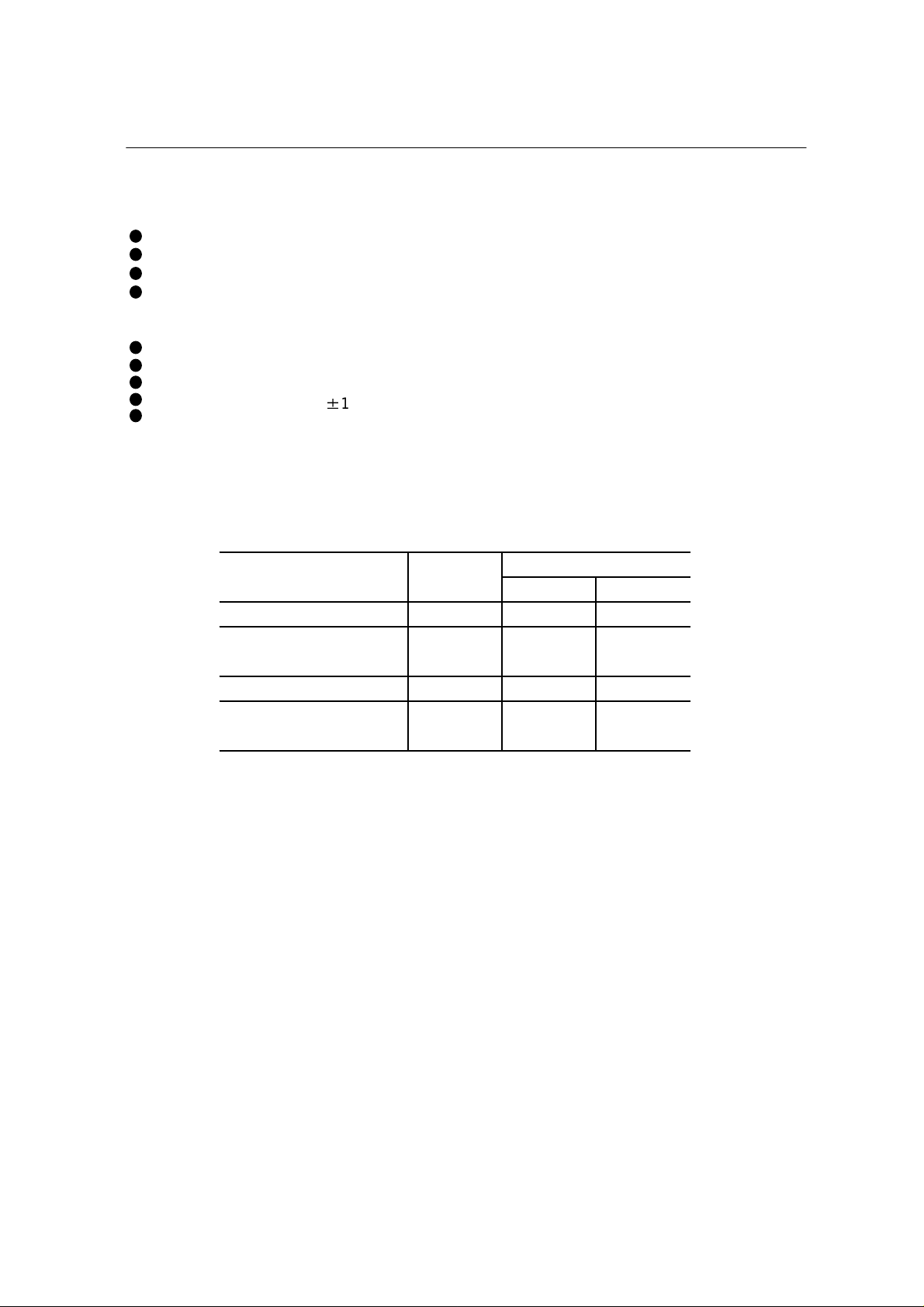
FEATURES
512 Rows x 512 columns x 8 bits x2
Fast FIFO(First-In First-Out)Operation :25ns cycle time
Self refresh(No refresh control is required)
High speed asynchronous serial access
Read/Write Cycle Time 25ns/30ns
Access Time 22ns/25ns
Variable length delay bit (600 to 262215)
Write mask function (Output enable control)
Cascading capability by mode setting
p
Single power supply:3.3V
Package:
100-Pin plastic TQFP(TQFP 100-P-1414-0.50-k)(Product:MS81V04160-xxTB)
xx indicates speed rank.
10%
Paramete r Symbol
M S81V04160-xxTB
-25 -30
Access Time
Read/Write
Cycl e Time
Operation current
Standby current 3mA 3mA
tAC 23ns 30ns
tSWC
25ns 30ns
tSRC
I cc1 80mA 80mA
Icc2
(MODE2 ="L")
2
Page 3
MS81V04160
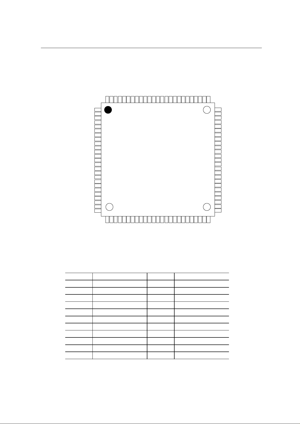
PIN CONFIGURATION (TOP VIEW)
OKI Semiconductor
NC
DI 23
Vss
DI 24
DI 25
DI 26
DI 27
NC
Vss
Vss
Vcc
Vcc
SWCK
Vcc
Vcc
Vss
Vss
NC
DI 17
DI 16
DI 15
DI 14
Vss
DI 13
NC
NC
88
38
NC
Vss
87
39
Vss
NC
86
40
NC
MODE1
RSTR2
OE2
RE2
Vcc
NC
81
82
83
84
85
45
44
43
42
41
RE1
RSTR1
Vcc
MODE3
MODE2
Vss
Vss
NC
NC
76
77
78
79
80
75
Vcc
74
DO 20
73
DO 21
72
Vss
71
DO 22
70
DO 23
69
DO 24
68
DO 25
67
Vss
66
DO 26
65
DO 27
64
Vcc
63
SRCK
62
Vcc
61
DO 17
60
DO 16
59
Vss
58
DO 15
57
DO 14
56
DO 13
55
DO 12
54
Vss
53
DO 11
52
DO 10
51
Vcc
50
49
48
47
46
NC
Vss
Vss
NC
OE1
RSTW2
DI 20
DI 21
DI 22
NC
100
98
99
1
2
3
4
5
6
7
8
9
10
11
12
13
14
15
16
17
18
19
20
21
22
23
24
25
28
27
26
DI 11
DI 12
NC
WE2
Vss
IE2
93
94
95
96
97
Vcc
92
Vss
91
NC
90
Vcc
89
100 PIN TQFP
TOP VIEW
37
36
35
34
33
32
31
30
29
Vcc
NC
Vss
Vcc
Vss
WE1
IE1
RSTW1
DI 10
Pin Name Pin Name
SWCK SRCK
WE1 WE2
RE1 RE2
IE1 IE2
OE1 OE2
RSTW1 RSTW2
RSTR1 RSTR2
DI 10-17 DI 20-27
DO 10-17 DO 20-27
MODE1,2,3
Vcc Vss
Function
Serial Write Clock
Port1 Write Inable
Port1 Read Inable
Port1 Input Inable
Port1 Output Inabl e
Port1 Reset Write
Port1 Reset Read
Port1 Data Input
Port1 Data Output
Mode Input
Power Supply(3.3V)
NC
Function
Serial Read Clock
Port2 Write Inable
Port2 Read Inable
Port2 Input Inable
Port2 Output Inabl e
Port2 Reset Write
Port2 Reset Read
Port2 Data Input
Port2 Data Output
No Connection
Ground(0V)
Note: The same power supply voltage must be provided to every Vcc pin,and
the same GND voltage level must be provided to every Vss pin.
3
Page 4
MS81V04160
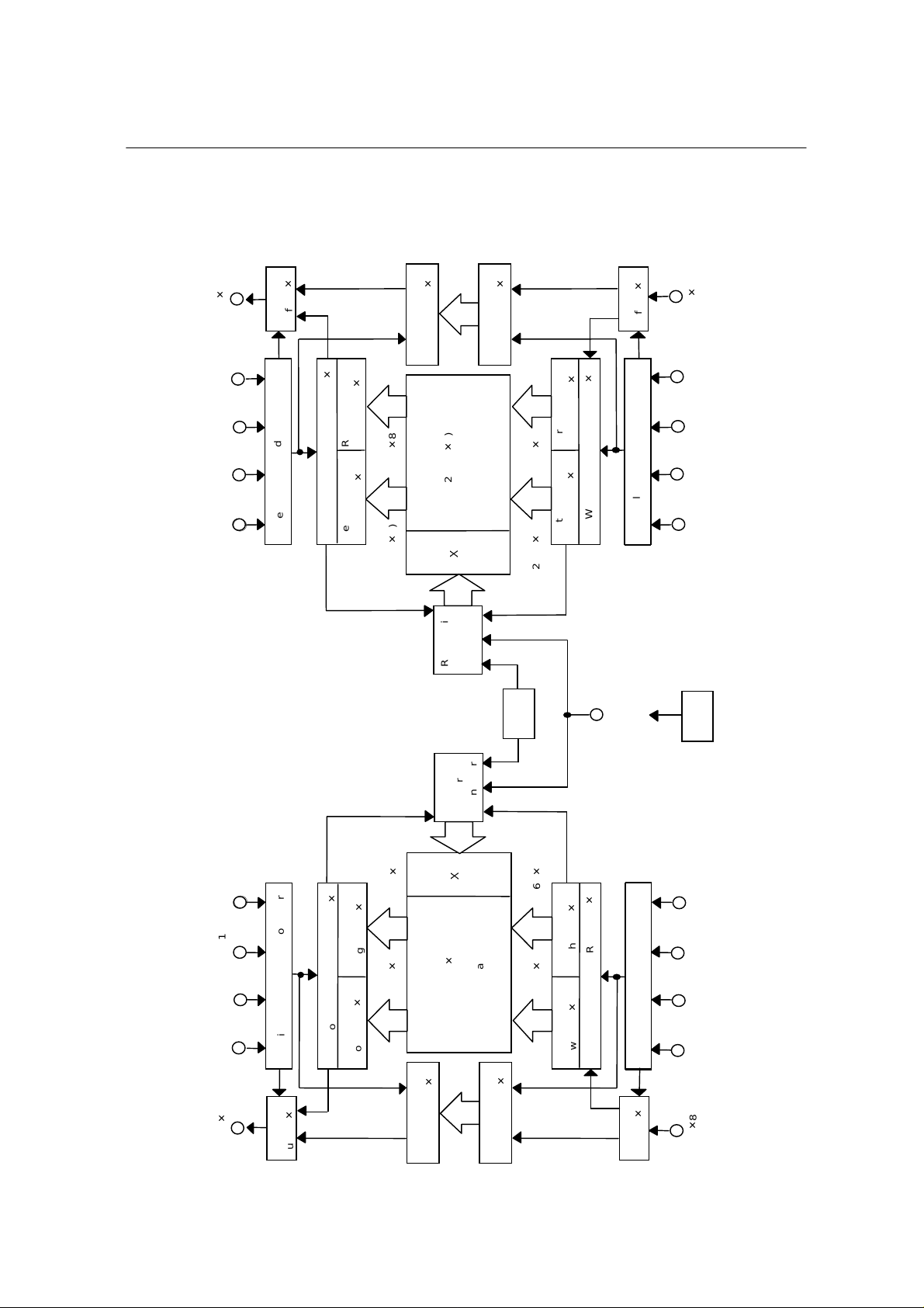
BLOCK DIAGRAM
OKI Semiconductor
8)
q
DO (
OE2
RE2
RSTR2
SRCK
Data-Out
Controller
Read
Serial
8)
q
Buffer (
8)
8)
q
q
Low-Half (
Read Line Buffer
8)
q
High-Half (
512 Word Serial Read Register (
Read Line Buffer
8)256 (
q
256 (
8)
q
8)
q
71 Word
Sub-Register (
8)
q
256k (
Read/Write
8)
q
71 Word
Sub-Register (
8)
q
Array
Memory
-
Decoder
Controller
and Refresh
256 (
8)
q
256 (
Clock
Oscillator
8)
8)
q
q
Low-Half (
Write Line Buffer
8)
q
High-Half (
Write Line Buffer
512 Word Serial Write Register (
8)
q
Data-In
Buffer (
ControllerSerial
Write
MODE1,2,3
8)
q
DI (
IE2
WE2RSTW2SWCK
VBB
Generator
RSTR1 SRCK
OE1
8)
q
DO (
Controller
Read/Write
and Refresh
8)
q
8)
8)
q
Controller
Read Line Buffer
Data-Out
Read
Serial
512 Word Serial Read Register (
Read Line Buffer
8)
q
Buffer (
RE1
256 (
q
8)
High-Half (
q
256 (
8)
q
Low-Half (
-
Decoder
8)
q
Array
Memory
256k (
8)
q
71 Word
Sub-Register (
71 Word
8)
q
8)
8)
q
q
Controller
8) 256 (
High-Half (
Write Line Buffer
q
256 (
8)
q
Low-Half (
512 Word Serial Write Register (
8)
q
Sub-Register (
Write Line Buffer
Write
Serial
8)
q
Data-In
Buffer (
SWCK
WE1 RSTW1
IE1
8)
q
DI (
4
Page 5

MS81V04160
OKI Semiconductor
PIN DESCRIPTION
Data Inputs: (DIN 10 - 17)
These pins are used for serial data inputs.
Write Reset: RSTW1
The first positive transition of SWCK after RSTW becomes high resets the write address
pointers to zero. RSTW1 setup and hold times are referenced to the rising edge of SWCK.
Because the write reset funct ion is so lely co ntrolled by the SWCK rising edge after the high
level of RSTW, the states of WE1 and IE1 are ignored in the write reset cycle. Before
RSTW1 may be brought high again for a further reset operation, it must be low for at least
two SWCK cycles.
Write Enable: WE1
WE1 is used for data write enable/disable control. WE1 high level enables the input, and
WE1 lowlevel disables the input and holds the internal write address pointer. There are no
WE1 disabletime (low) and WE1 enable time (high) restrictions, because the MS8104160
is in fully static operation as long as the power is on. Note that WE1 setup and hold times
are referenced to t he rising ed ge of SWCK.
Input Enable: IE1
IE1 is used to enable/disable writing into memory. IE1 high level enables writing. The
internal write address pointer is always incremented by cycling SWCK regardless of the
IE1 level. Note that IE1 setup and hold times are referenced to the rising edge of SWCK.
Data Out: (DOUT 0 - 11)
These pins are used for serial data outputs.
Read Reset: RSTR1
The first positive transition of SRCK after RSTR1 becomes high resets the read address
pointers to zero. RSTR1 setup and hold times are referenced to the rising edge of SRCK.
Because the read reset function is solely controlled by the SRCK rising edge after the high
lev el of RSTR, the states of RE1 and OE1 are ign ored in the read reset cyc le. Before RST R
may be brought high again for a further reset operation, it must be low for at least *two
SRCK cycles.
Read Enable: RE1
The function of RE1 is to gate of the SRCK clock for incrementing the read pointer. When
RE1 is high before the rising edge of SRCK, the read pointer is incremented. When RE1 is
low, the read pointer is not incremented. RE1 setup times (tRENS and tRDSS) and RE1
hold times (tRENH and tRDSH) are referenced to the rising edge of the SRCK clock.
Output Enabl e: OE1
OE1 is used to enable/disable the outputs. OE1 high level enables the outputs. The internal
read address pointer is always incremented by cycling SRCK regardless of the OE1 level.
Note that OE1 setup and ho ld t ime s are referenced to the rising edge of SRCK.
5
Page 6

MS81V04160
Serial Write Cl ock: SWCK
The SWCK latches the input data on chip when WE1, 2 is high, and also increments the
internal write address pointer. Data-in setup time tDS, and hold time tDH are referenced to
the rising edge of SWCK.
Serial Read Clock: SRCK
Data is shifted out of the data registers. It is triggered by the rising edge of SRCK when
RE1, 2 is highduring a read operation. The SRCK input increments the internal read
address pointer when RE1,2 is high.
The three-state output buffer provide s dire ct TTL compatib ilit y (no pullup resistor req uire d).
Data out is the same polarity as data in. The output becomes valid after the access time
interval tAC that begins with the rising edge of SRCK. *There are no output valid time
restriction on MS8104160.
Data Input: (DIN 20-27)
These pins are used for serial data inputs.
Write Reset: RSTW2
The first positive transition of SWCK after RSTW becomes high resets the write address
pointers to zero. RSTW2 setup and hold times are referenced to the rising edge of SWCK.
Because the write reset funct ion is sol ely controlled by the S WCK rising ed ge after the high
level of RSTW2, the states of WE2 and IE2 are ignored in the write reset cycle. Before
RSTW2 may be brought high again for a further reset operation, it must be low for at least
two SWCK cycles.
OKI Semiconductor
Write Enable: WE2
WE is used for data write enable/disable control. WE2 high level enables the input, and
WE2 lowlevel disables the input and holds the internal write address pointer. There are no
WE2 disabletime (low) and WE2 enable time (high) restrictions, because the MS8104160
is in fully static operation as long as the power is on. Note that WE2 setup and hold times
are referenced to the rising edge of SWCK.
Input Enable: IE2
IE2 is used to enable/disable writing into memory. IE2 high level enables writing. The
internal write address pointer is always incremented by cycling SWCK regardless of the
IE2 level. Note that IE2 setup and hold times are referenced to the rising edge of SWCK.
DOUT 20 – 27
Data Out :
These pins are used for serial data outputs.
Read Reset: RSTR2
The first positive transition of SRCK after RSTR2 becomes high resets the read address
pointers to zero. RSTR2 setup and hold times are referenced to the rising edge of SRCK.
Because the read reset functio n is solely controlled by the SRCK rising edge after the high
level of RSTR2, the states of RE2 and OE2 are ignored in the read reset cycle. Before
RSTR2 may be brought high again for a further reset operation, it must be low for at least
*two SRCK cycles.
6
Page 7

MS81V04160
Output Enabl e: OE2
OE2 is used to enable/disable the outputs. OE2 high level enables the outputs. The internal
read address pointer is always incremented by cycling SRCK regardless of the OE2 level.
Note that OE2 setup and ho ld t ime s are referenced to the rising edge of SRCK.
Mode Setting: MODE1
The Cascade/Non cascade select pin. Setting the MODE1 pin to the Vcc level configures
this memory device as cascade type and se tting the pin to the Vss level configures this
memory device as non cascade. During memor y operation, the pin must be per manentry
connected to Vcc or Vss. If a MODE1 level is changed during memory operation, memory
data is not guaranteed.
Note: Cascade/Non cascade
When MODE1 is set to the Vss level, memory accessing starts in the cycle in which the
control signals are input (Non cascad e t ype).
When MODE1 is set to the Vcc level, memory accessing starts in the cycle subsequent to
the cycle in which the control signals are input (Cascade type). This type is used for
consecutive memory accessing.
MODE2 Setting: MODE2
MODE2 selects whether the control input signals are enabled at a high level or a low level.
Setting MODE2 to the Vcc level enables the control input signals at a low level and setting
MODE2 to the Vss level enables the control input signals at a high level.
OKI Semiconductor
MODE Setting: MODE3
The boost control pin for data-out Buffer. For the MS8104160, the MODE3 pin should be
permanentry Connected to the Vss level.
7
Page 8

MS81V04160
OKI Semiconductor
ELECTRICAL CHARACTERISTICS
Absolute Maximum Ratings
Parameter
Input Output Voltage
Output Current
Power Dissipation
Operating Temperature
Storage Temperature
Symbol
T
V
I
OS
P
D
T
opr
T
stg
Condition
at Ta = 25oC, V
Ta = 25oC
Ta =25oC
¥
¥
SS
Rating
-1.0 to 4.6
50
1
0 to 70
-55 to 150
Recommended Operating Conditions
Parameter Symbol Min. Typ. Max. Unit
Power Supply Voltage VCC 3.0 3.3 3.6 V
SS
Power Supply Voltage V
Input High Voltage VIH 2.4 V
Input Low Voltage VIL -0.3 0
0 0 0 V
CC VCC
+ 0.3 V
0.8 V
Unit
V
mA
W
o
o
C
C
DC Characteristics
Parameter Symbol Condition Min. Max. Unit
Input LeadKage Current ILI
Output LeadKage Current I
0 < VI< VCC, Other Pins Tested at V=0V
LO
0 < VO< V
CC
Output “H” Level Voltage VOH IOH = -1 mA 2.4 - V
Output “ L” Level Voltage VOL IOL = 2 mA - 0.4 V
CC1
Operating Current I
I
Standby Current
I
Minimum Cycle Time, Output Open
CC2A
Input Pin = VIH / V
CC2B
MODE2=“L”
IL
MODE2=“H”
Capacitance
Parameter Symbol Max. Unit
IN
Input Capacitance (D
Outnput Capacitance (D
,SWCK,SRCK,RSTW,RSTR,WE,RE,IE,OE) C
OUT
) C
-10 10 uA
-10 10 uA
- 80 mA
- 3
- 10
o
(Ta = 25
C , f = 1 MHz)
I
O
7 pF
7 pF
mA
8
Page 9

MS81V04160
OKI Semiconductor
AC Characteristics
Parameter
Access Time from SRCK
DOUT Hold Time from SRCK
DOUT Enable Time from SRCK
SWCK "H" Pulse Width
SWCK "L" Pulse Width
Input Time Data Setup
Input Data Hold Time
WE Enable Setup Time
WE Enable Hold Time
WE Disable Setup Time
WE Disable Hold Time
IE Enable Setup Time
IE Enable Hold Time
IE Disable Setup Time
IE Disable Hold Time
WE "H" Pulse Width
WE "L" Pulse Width
IE "H" Pulse Width
IE "L" Pulse Width
RSTW Setup Time
RSTW Hold Time
SRCK "H" Pulse Width
SRCK "L" Pulse Width
RE Enable Setup Time
RE Enable Hold Time
RE Disable Setup Time
RE Disable Hold Time
OE Enable Setup Time
OE Enable Hold Time
OE Disable Setup Time
OE Disable Hold Time
RE "H" Pulse Width
RE "L" Pulse Width
OE "H" Pulse Width
OE "L" Pulse Width
RSTR Setup Time
RSTR Hold Time
SWCK Cycle Time
SRCK Cycle Time
Transition Time (Rise and Fall)
( Vcc = 3.0 - 3.6V,Ta = 0 to 70oC )
MS81V04160-30
Min. Max.
23
-
6
6
20 ns
20 ns
5
-
-
5
-
-
5
-
5
-
5
5 (7)
-
-
5
-
5
-
5
10
10
10
10
-
-
3
-
10
-
20
-
20
-
3
-
5
-
3
-
5
-
3
-
5
-
3
-
5
10
-
-
10
-
10
10
-
-
3
10
-
30
-
30
-
30
3
30 ns
-
ns
30 ns
-
-
-
ns
-
ns
-
ns
-
ns
-
ns
-
ns
-
ns
-
ns
-
ns
-
ns
-
ns
-
ns
-
ns
-
ns
-
ns
-
ns
-
ns
-
ns
-
ns
-
ns
-
ns
-
ns
-
ns
-
ns
-
ns
-
ns
-
ns
-
ns
-
ns
-
ns
-
ns
-
ns
-
ns
-
ns
30 ns
t
AC
DDCK
DECK
WSWH
WSWL
t
DS
t
DH
WENS
WENH
WDSS
WDSH
IENS
IENH
IDSS
IDSH
WWEH
WWEL
WIEH
WIEL
WSRH
WSRL
RENS
RENH
RDSS
RDSH
OENS
OENH
ODSS
ODSH
WREH
WREL
WOEH
WOEL
SWC
SRC
t
T
MS81V04160-25
Min. Max.
6623
15 15 -
3
5
5 (7) 5 (7)
5
5
5
5 (7)
5
5
5
5
5
5
5
3
10
15
15
3
5
3
5
3
5
3
5
5
5
5
5
3
10
25
25
3
Symbol Unit
t
t
t
t
t
t
t
t
t
t
t
t
t
t
t
t
t
RSTWS
t
RSTWH
t
t
t
t
t
t
t
t
t
t
t
t
t
t
t
RSTRS
t
RSTRH
t
t
9
Page 10

MS81V04160
OKI Semiconductor
Notes: 1. Input signal reference levels for the parameter measurement are V
V
between V
2. AC measureme nt s assume t
= 0 V. The transition time tT is defined to be a trans itio n t ime that sig nal t ransfers
IL
= 3.0 V and V
IH
IL
= 0 V.
= 3 ns.
T
= 3.0 V and
IH
3. Read address must have more than a 600 address delay than write address in
every cycle when asynchronous read/write is performed.
4. Read must ha v e more than a 6 00 addres s dela y tha n write in order to read the dat a
written in a current series of write cycles which has been started at last write reset
cycle: this is called "new data read". When read has less than a 70 address delay
than write, the read data are the data written in a previous series of write cycles
which had been written before at last write reset cycle: this is called "old data read".
5. When t he read address delay is between more than 71 and less than 599 or more
than 262,214, read data will be undetermined. Ho w e v er, normal write is achieved in
this address condition.
6. Outputs are measured with a load equivalent to 1 TTL load and 30 pF. Output
reference levels are V
= 1.5 V and V
OH
OL
= 1.5 V.
7. ( ): MODE2=Vcc
10
Page 11

MS81V04160
OKI Semiconductor
OPERATION MODE
Write Operation Cyc l e (MO DE2=Vss)
The write operation is controlled by seven control signals, SWCK, RSTW1, RSTW2, WE1,
WE2 and IE1, IE2. Port1 write operation is accomplished by cycling SWCK, and holding
WE1 high after the write address pointer reset operation or RSTW1. RSTW1 must be
preformed for int ernal circu it initialization before Write op eration.
Each write operation, which begins after RSTW1, must contain at least 80 active write
cycles, i.e. SW CK cycles w hile WE1 and IE1 are h igh. To transfer the last data to the DRA M
array, which at that time is stored in the serial d ata registers at tached to the DRAM arr a y, an
RSTW1 operation is required after the last SWCK cycle.
Note that ever y write timing of MS8104160 is delayed by one clock compared with read
timings for easy c ascading without any interface delay devices.
Setting MODE1 to the Vss level starts write data accessing in the cycle in which RSTW1,
WE1, and IE1 control signal s are input.
Setting MODE1 to the Vcc level starts write data accessing in the cycle subsequent to the
cycle in which RSTW 1, WE1, and IE1 control signals are input.
These operation are t he same for Port1 and Port2.
Settings of WE1, 2 and IE1, 2 to t he o peration mode of Write addres s poi nter a nd
Data input.
WE1,2 IE1,2
HH
HL
LX
Incremented
Halted
Data inputInternal Write address pointer
Input
Not input
X indicates "don't care"
Write Operation Cyc l e (MO DE2=Vcc)
The write Operation is controlled by seven control signal s, SWCK, RSTW1, RSTW2, WE1,
WE2, and IE1, IE2. Port1 write operation is accomplished by cycling SWCK and holding
both WE1 and IE1 low after the write address pointer reset operation or RSTW1. RSTW1
must be perf ormed for internal circuit initialization before write operation.
Each write operation, which begins after RSTW1, must contain at least 80 active write
cycle, i.e. SWCK cycles while WE1 and IE1 are high. To transfer the last data to the DRAM
array, which at that time is stored in the seria l data registers attached to the DRAM array,
an RSTW1 operation is required after the last SWCK cycle.
Note that ever y write timing of MS8104160 is delayed by one clock compared with read
timings for easy c ascading without any interface delay devices.
Setting MODE1 to the Vss level starts write data accessing in the cycle in which
RSTW1.WE1, and IE1 cont rol signals are input.
Setting MODE1 to the Vcc level starts write data accessing in the cycle in which RSTW1,
WE1, and IE1 control signal s are input.
Setting MODE1 to the Vcc level starts write data accessing in the cycle subsequent to the
cycle in which RSTW 1, WE1, and IE1 control signals are input.
These operations are t he same for port1 and Port2.
11
Page 12

MS81V04160
Settings of WE1, 2 and IE1, 2 to the operation mode of Write address pointer and Data
input.
OKI Semiconductor
WE1,2 IE1,2
LL
LH
HX
Internal Write address pointer Data input
Incremented
Halted
Input
Not input
X indicates "don't care"
Read Operation Cycle (MODE2=Vss)
The read operation is controlled by seven control signals, SRCK, RSTR1, RSTR2, RE1,
RE2, and OE1, OE2. Port1 read operation is accomplished by cycling SRCK, and holding
both RE1 and OE1 high after the read address pointer reset operation or RSTR1.
Each read operation, which begins after RSTR1, must contain at least 80 active read
cycles, i.e. SRCK cycles while RE1 and O E1 are high.
These operations are t he same for Port1 and Port2.
Settings of RE1, 2 and OE 1, 2 to the operation mode of read address pointer and Data
output.
RE1,2 OE1,2
HH
HL
LH
LL
Internal Write address pointer Data output
Incremented
Halted
Output
High impedance
Output
High impedance
Read Operation Cycle (MODE2=Vcc)
The read operation is controlled by seven control signals, SRCK, RSTR1, RSTR2, RE1,
RE2, and OE1, OE2. Port1 read operation is accomplished b y cy cl ing S RCK, and h oldi ng
both RE1 and OE1 high after the read address pointer reset operation or RSTR1.
Each read operation, which begins after RSTR1, must contain at least 80 active read
cycles, i.e. SRCK cycles while RE1 and OE1 are low.
These operations are t he same for Port1 and Port2.
Settings of RE1, 2 and OE 1, 2 to the operation mode of read address pointer and Data
output.
RE1,2 OE1,2
LL
LH
HL
HH
Internal Write address pointer Data output
Incremented
Halted
Output
High impedance
Output
High impedance
12
Page 13

MS81V04160
Power-up and Initialization
On power-up, the device is designed to begin proper operation after at least 100 us after
Vcc has stabilized to a value within the range of recommended operating conditions. After
this 100 us stabilization interval, the following initialization sequence must be performed.
Because the read and write address pointers are undefined after power-up, a minimum of
80 dummy write operations (SWCK cycles) and read operations (SRCK cycles) must be
performed, followed by an RSTW1, 2 operation and an RSTR1, 2 operation, to properly
initialize the write and the read address pointer. Dummy write cycles/RSTW1, 2 and
dummy read cycles/RSTR1, 2 may occ ur simultaneously.
If these dummy read and write operations sta rt while Vcc and/or the substrate voltage has
not stabilized, it is necessary to perform an RSTR1, 2 operation plus a minimum of 80
SRCK cycles plus another RSTR1,2 operation, and an RSTW1,2 operation plus a
minimum of 80 SWCK cycles plus another RSTW1,2 operation to properly initialize read
and write address pointers .
Old/New Data Access
There must be a minimum delay of 600 SWCK cycles between writing into memory and
reading out from memory. If reading from the first field starts with an RSTR1, 2 operation,
before the start of writing the second field (before the next RSTW1, 2 operation), then the
data just written will be read out .
The start of reading out the first field of data ma y be de la y ed p ast the begin ning of writi ng in
the second field of data for as many as 70 SWCK cycles. If the RSTR1, 2 operation for the
first field read-out occurs less than 70 SWCK cycles after the RSTW1, 2 operation for the
second field write-in, then the internal buffering of the device assures that the first field will
still be read out. The first field of data that is read out while the second field of data is
written is called “old data”. In order to read out “new data”, i.e., the second field written in,
the delay between an RSTW1, 2 operation and an RSTR1, 2 operation must be at least
600 SRCK cycles. If the delay between RSTW1, 2 and RSTR1, 2 operations is more than
71 but less than 600 cycles, then the data read out will be undetermined. It may be “old
data” or “new” data, or a combination of old and new data. Such a timing should be
avoided.
OKI Semiconductor
13
Page 14

MS81V04160
TIMING WAVEFORM
Write Cycle Timing (Write Reset) : MODE1=Vcc , MODE2=Vss
OKI Semiconductor
SWCK
RSTW 1, 2
DI
10-17/20-27
IE 1,2
WE 1,2
n cycle
tRSTWS
0 cycle 1 cycle 2 cycle
tRSTWH
tWSWH tWSWL
tSWC
tDS
tDH
n-1 n 0 1 2
IH
V
IL
V
IH
V
IL
V
IH
V
IL
V
V
IH
V
IL
V
IH
V
IL
Write Cycle Timing (Write Enable) : MODE1=Vcc , MODE2=Vss
SWCK
WE 1,2
DI
10-17/20-27
IE 1,2
RSTW 1, 2
n cycle
tWENH
tWWEL
n-1 n
Disable cycle n+1 cycl e
Disable cycle
tWDSH
tWENS
tWDSS
tWWEH
n+1
IH
V
IL
V
IH
V
IL
V
IH
V
IL
V
IH
V
IL
V
IH
V
IL
V
14
Page 15

MS81V04160
Write Cycle Timing (Input Enable) : MODE1=Vcc , MODE2=Vss
OKI Semiconductor
SWCK
IE 1,2
DI
10-17/20-2 7
WE 1,2
RSTW 1, 2
n cycle n+1 cycle n+3 cycle
tIENH
tIDSH
tWIEL
n+2 cycl e
tIENS
tIDSS
tWIEH
n-1 n
n+3
IH
V
IL
V
IH
V
IL
V
IH
V
IL
V
IH
V
IL
V
IH
V
IL
V
Write Cycle Timing (Write Reset) : MODE1=Vcc , MODE2=Vcc
n cycle 0 cycle
SWCK
tWSWH tWSWL
RSTW 1, 2
DI
10-27/20-27
WE 1,2
IE 1,2
tDS tDH
n-1
tRSTWS
tRSTWH
n012
1 cycle
tSWC
2 cycle
IH
V
IL
V
IH
V
IL
V
IH
V
IL
V
IH
V
IL
V
IH
V
IL
V
15
Page 16

MS81V04160
Write Cycle Timing (Write Enable) : MODE1=Vcc , MODE2=Vcc
OKI Semiconductor
SWCK
WE 1,2
DI
10-17/20-2 7
IE 1,2
RSTW1,2
n cycle
tWENH
tWWEL
n-1 n
Disable cycle n+1 cycl e
Disable cycle
tWDSH
tWDSS
tWENS
tWW EH
n+1
IH
V
IL
V
IH
V
IL
V
IH
V
IL
V
IH
V
IL
V
IH
V
IL
V
Write Cycle Timing (Input Enable) : MODE1=Vcc , MODE2=Vcc
SWCK
IE 1,2
DI
10-17/20-2 7
WE 1,2
RSTW 1, 2
n cycle n+1 cy c l e n+3 cycle
tIENH
tIDSH
tWIEL
tWIEH
n-1 n n+3
tIDSS
n+2 cycl e
tIENS
IH
V
IL
V
IH
V
IL
V
IH
V
IL
V
IH
V
IL
V
IH
V
IL
V
16
Page 17

MS81V04160
Write Cycle Timing (Write Reset) : MODE1=Vss , MODE2=Vss
OKI Semiconductor
SWCK
RSTW 1, 2
DI
10-17/20-27
WE 1,2
IE 1,2
n cycle 0 cycl e 1 cycle 2 cycle
tRSTWS
tRSTWH
tWSW H
tWSW L
tSWC
tDS
tDH
n0123
IH
V
IL
V
IH
V
IL
V
IH
V
IL
V
IH
V
IL
V
IH
V
IL
V
Write Cycle Timing (Write Enable) : MODE1=Vss , MODE2=Vss
SWCK
WE 1,2
DI
10-17/20-2 7
IE 1,2
RSTW 1, 2
n cycle Disable cycle n+1 cycle
tWENH
tWDSH
tWWEL
tWWEH
nn+1n
Disable cycle
tWENS
tWDSS
IH
V
IL
V
IH
V
IL
V
IH
V
IL
V
IH
V
IL
V
IH
V
IL
V
17
Page 18

MS81V04160
Write Cycle Timing (Input Enable) : MODE1=Vss , MODE2=Vss
OKI Semiconductor
SWCK
IE 1,2
DI
10-17/20-2 7
WE 1,2
RSTW 1, 2
n cycle n+1 cycle n+3 cycle
tIENH
tIDSH
tWIEL
n+2 cycl e
tIENS
tIDSS
tWIEH
nn
n+3
n+4
IH
V
IL
V
IH
V
IL
V
IH
V
IL
V
IH
V
IL
V
IH
V
IL
V
Write Cycle Timing (Write Reset) : MODE1=Vss , MODE2=Vcc
SWCK
RSTW 1, 2
DI
10-27/20-27
WE 1,2
IE 1,2
n cycle 0 cycle
tDS tDH
n-1 n 0 1 2
n-1 cycle
tRSTWS
tRSTWH
1 cycle
tWSWH tWSWL
tSWC
2 cycle
IH
V
IL
V
IH
V
IL
V
IH
V
IL
V
IH
V
IL
V
IH
V
IL
V
18
Page 19

MS81V04160
Write Cycle Timing (Write Enable) : MODE1=Vss , MODE2=Vcc
OKI Semiconductor
SWCK
WE 1,2
DI
10-17/20-2 7
IE 1,2
RSTW1,2
tWENH
n
n cycle
tWWEL
Disable cycle n+1 cycl e
Disable cycle
tWDSH
tWDSS
tWENS
tWW EH
n+1
n+2
n+2 cycl e
IH
V
IL
V
IH
V
IL
V
IH
V
IL
V
IH
V
IL
V
IH
V
IL
V
Write Cycle Timing (Input Enable) : MODE1=Vss , MODE2=Vcc
SWCK
IE 1,2
DI
10-17/20-2 7
WE 1,2
RSTW 1, 2
n cycle n+1 cyc le n+3 cycle
tIENH
tIDSH
tWIEL
tWIEH
n
tIDSS
n+2 cycl e
tIENS
n+3
n+4
IH
V
IL
V
IH
V
IL
V
IH
V
IL
V
IH
V
IL
V
IH
V
IL
V
19
Page 20

MS81V04160
Read Cycle Timing (Read Reset) : MODE1=Vcc/Vss , MODE2=Vss
OKI Semiconductor
SRCK
RSTR 1,2
DO
10-17/20-27
RE 1,2
OE 1,2
n cycle
0 cycle
tRSTRS tRSTRH
1 cycle
tWSRH tWSRL
2 cycle
tSRC
tAC
tDDCK
n-1 n 0 1 2
IH
V
IL
V
IH
V
V
IL
V
OH
V
OL
IH
V
IL
V
V
IH
IL
V
Read Cycle Timing (Read Enable) : MODE1=Vcc/Vss , MODE2=Vss
SRCK
RE 1,2
DO
10-17/20-27
OE 1,2
RSTR 1,2
n cycle Disable cycle n+1 cycle
tRENH
tRDSH
tWREL
tWREH
n-1
Disable cycle
tRENS
tRDSS
n
n+1
V
IH
V
IL
V
IH
V
IL
V
OH
V
OL
V
IH
V
IL
V
IH
V
IL
20
Page 21

MS81V04160
OKI Semiconductor
Read Cycle Timing (Output Enable) : MODE1=Vcc/Vss , MODE2=Vss
SRCK
OE 1,2
DO
10-17/20-27
RE 1,2
RSTR 1,2
n cycle n+1 cycle n+3 cycle
tOENH
tODSH
tWOEL
n+2 cycl e
tOENS
tODSS
tWOEH
n-1 n
Hi-Z
tDECK
n+3
V
IH
V
IL
V
IH
V
IL
V
OH
V
OL
V
IH
V
IL
V
IH
V
IL
Read Cycle Timing (Read Reset) : MODE1=Vcc/Vss , MODE2=Vcc
SRCK
RSTR 1,2
DO
10-17/20-27
RE 1,2
OE 1,2
n cycle 1 cycle 2 cy cle
tRSTRS tRSTRH
tAC
n-1 n
0 cycle
tWSRH
tDECK
0
12
tSRC
tWSRL
V
IH
V
IL
V
IH
V
IL
V
OH
V
OL
V
IH
V
IL
V
IH
V
IL
21
Page 22

MS81V04160
OKI Semiconductor
Read Cycle Timing (Read Enable) : MODE1=Vcc/Vss , MODE2=Vcc
SRCK
RE 1,2
DO
10-17/20-27
OE 1,2
RSTR 1,2
n cycle
tRENH
Disable cycle
tRDSH
tRDSS
tWREL
tAC
tWREH
n-1 n
Disable cycle
tRENS
n+1 cycl e
n+1
IH
V
IL
V
IH
V
V
IL
V
OH
V
OL
IH
V
IL
V
V
IH
V
IL
Read Cycle Timing (Output Enable) : MODE1=Vcc/Vss , MODE2=Vcc
SRCK
OE 1,2
DO
10-17/20-27
RE 1,2
RSTR 1,2
n cycle
tOENH
tWOEL
n-1 n
n+1 cycle n+3 cycle
tODSH
tWOEH
n+2 cycl e
tODSS
tOENS
Hi-Z
n+3
IH
V
IL
V
IH
V
V
IL
V
OH
V
OL
IH
V
IL
V
V
IH
IL
V
22
 Loading...