

Page 1
MITSUMI
Regulator+Reset IC MM1481
Regulator+Reset IC
Monolithic IC MM1481
Outline
This IC was developed for use in CD-ROM drives and other optical disc drives. It combines two 3V system
regulator lines and reset (monitors regulator input) with a built-in 4.2V detection delay circuit that responds to
market needs.
Features
1. Large output current 300mA max.
2. High ripple rejection rate regulator1: 80dB typ. regulator2: 60dB typ.
3. Internal thermal shutdown circuit.
4. Internal current-limiting circuit.
5. Adjustment-free reset detection voltage 4.2V typ.
6. Easy to set delay time from voltage detection to reset release.
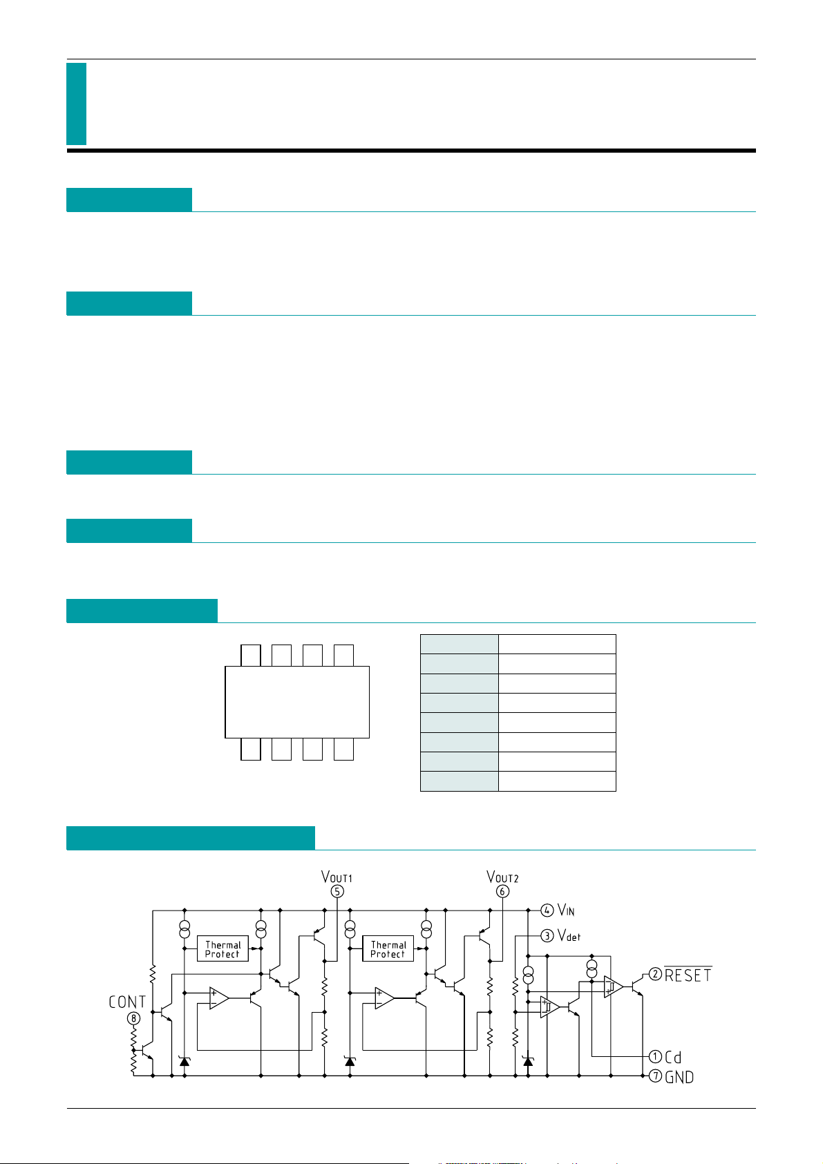
Package
VSOP-8A
Applications
Pin Assignment
Equivalent Circuit Diagram
1. CD-ROM drive
2. Optical disc drives
1423
7685
VSOP-8A
(TOP VIEW)
MITSUMI
1 Cd
2 RESET
---------------------------------------------------------------------
3 Vdet
4 V
IN
5 VOUT1
6 V
OUT2
7 GND
8 CONT
Page 2
MITSUMI
Regulator+Reset IC MM1481
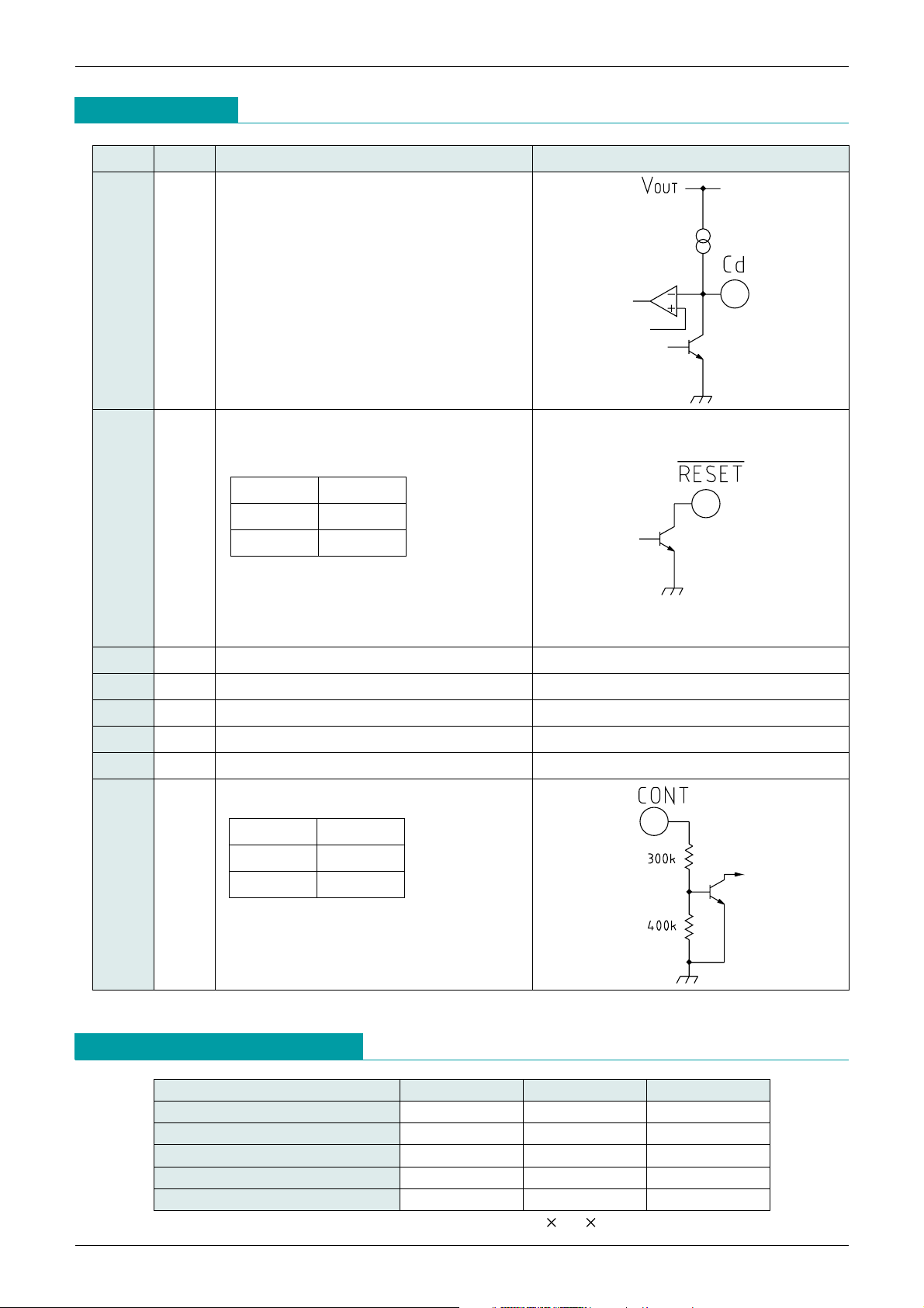
Pin Description
Absolute Maximum Ratings
MITSUMI
Item Symbol Ratings Unit
Storage temperature T
STG
-
40~+125 °C
Supply voltage V
IN
-
0.3~+10 V
Output current 1 I
OUT1 300 mA
Output current 2 I
OUT2 200 mA
Power dissipation Pd 550
*
mW
Note: *When mounted on a (Copper foil area 80%, 100 100 1.6tmm) glass epoxy board.
1 Cd Delay time capacitor pin
The delay time of RESET output can be set
according to the capacity value connected
with Cd
t
PLH=450000 · C
t
PLH1: Delay Time [s]
C: Cd-capacitance [F]
2 RESET RESET
---------------------------------------------------------------------
-output pin
RESET
---------------------------------------------------------------------
pin logic
When the voltage of V
IN decreases to 1.6V
or less, it is likely to become "L" regardless
of Vdet voltaege.
3 Vdet Voltage-supply pin (reset)
4 V
IN Voltage-supply pin
5 V
OUT1 Regulator output pin (150mA)
6 V
OUT2 Regulator output pin (100mA)
7 GND GND pin
8 CONT V
OUT1 ON/OFF-control pin
Connect cont-terminal with V
IN, when it is
not used.
Pin No.
Pin Name
Functions Equivalent circuit diagram
__
RESET
Vdet<VS L
Vdet>VS H
VCONT VOUT1
L OFF
HON
Page 3

Item Symbol Measurement conditions Min. Typ. Max. Unit
V
IN Input Current 1 Iccq1 VIN=5V IOUT1=1OUT2=0mA 2.1 4.2 mA
V
IN Input Current 2
Iccq2 V
IN=5V Vcont=0.4V IOUT2=0mA 300 500 µA
(V
OUT1
-
OFF)
Vdet Input Current 1 Iccq3 Vdet=5V 20 40 µA
Regulator 1 (150mA output)
Output Voltage V
OUT1 VIN=5V IOUT1=30mA 3.52 3.60 3.68 V
Input-Output differential Voltage
ViO VIN=3.4V IOUT1=70mA 0.13 0.26 V
Line Regulation V1 V
IN=4.4V~5.5V IOUT1=30mA 1 20 mV
Load Regulation V2 V
IN=5V IOUT1=0mA~150mA 20 120 mV
V
OUT
Temperature Coefficient *1
V
OUT
/ T
Tj=-20~+80°CVIN=5V I
OUT1
=30mA
100
ppm/°C
Ripple Rejection *1 RR
V
IN=5V f=120Hz
V
RIPPLE=1VP-P, IOUT1=30mA
50 80 dB
Output Noise Voltage
*
1 Vn VIN=5V, f=20~80kHz IOUT1=30mA 100
µVrms
CONT Terminal Current when ON
I
ON Vcont=1.6V 5 10 µA
HIGH Threshold Voltage H 1.6
VIN+0.3
V
LOW Threshold Voltage L
-
0.3 0.4 V
Regulator 2 (100mA output)
Output Voltage V
OUT2 VIN=5V IOUT2=20mA 3.52 3.60 3.68 V
Input-Output differential Voltage
Vi0 VIN=3.4V IOUT2=20mA 0.07 0.14 V
Line Regulation V1 V
IN=4.4V~5.5V IOUT2=20mA 10 20 mV
Load Regulation V2 V
IN=5V IOUT2=0mA~100mA 20 120 mV
V
OUT
Temperature Coefficient *1
V
OUT
/ T
Tj=-20~+80°C
V
IN=5V IOUT2=20mA
100
ppm/°C
Ripple Rejection *1 RR
V
IN=5V f=120Hz
V
RIPPLE=1VP-P, IOUT2=20mA
50 60 dB
Output Noise Voltage
*
1 Vn VIN=5V, f=20~80kHz IOUT2=20mA 150
µVrms
MITSUMI
Regulator+Reset IC MM1481
MITSUMI
Electrical Characteristics
(Except where noted otherwise, Ta=25°C, VCONT=1.6V)
Recommended Operating Conditions
(Except where noted otherwise, Ta=25°C)
Item Symbol Ratings Unit
Operating temperature T
OP
-
20~+85 °C
Output current 1 I
OP1 0~150 mA
Output current 2 I
OP2 0~100 mA
Operating voltage V
OP 0~10 V
Note 1: design guaranteed
Page 4

MITSUMI
Regulator+Reset IC MM1481
MITSUMI
Application Circuit
Note 1 : This regulator is not internally compensated and thus requires an external output-capacitor (C
OUT
) for
stability.
Note 2 : Please be careful with regard to set wiring and temperature-related capacitor changes that may cause
oscillation.
Measuring Circuit
Item Symbol Measurement conditions Min. Typ. Max. Unit
Detecting Voltage VS Vdet=H L 4.11 4.20 4.29 V
Vs temperature Coefficient *VS/ T
Ta=-20~+80°C 100
ppm/°C
Hysteresis Voltage VS Vdet=H L H 100 200 mV
Low-Level Output Voltage V
OL Vdet=3.9V RL=4.7k 100 200 mV
Output Leakage Current I
OH Vdet=5V ±0.1 µA
Output Current when ON 1 I
OL Vdet=3.9V, RL=0 5 mA
Output Current when ON 2
*
IOL Vdet=3.9V, RL=0 Ta=-20~+80°C 3 mA
"H" Transmission Delay Time *tPLH Cd Pin open 30 90 µs
Reset Delay Time
*
tPLH1 Vdet=4V 5V, Cd=0.22µF 5 10 15 ms
"L" Transmission Delay Time *tPHL Cd Pin open 30 90 µs
Threshold Operating Voltage
VOPL VOL=0.4V 0.65 0.85 V
Electrical Characteristics
(Typical model MM1481C) (Except where noted otherwise, Ta=25°C, V
CONT
=1.6V)
(Except where noted otherwise, resistance unit is Ω)
Part of RESET
Note 1: design guaranteed
Page 5

MITSUMI
Regulator+Reset IC MM1481
Timing Chart
tPLH
Vs
VIN. Vdet
VOUT1
CONT
5V
Vs
0V
5V
0V
VOUT2
5V
0V
5V
0V
H
L
RESET
Page 6

MITSUMI
Regulator+Reset IC MM1481
MITSUMI
Characteristics
Detection voltage (IOUT=0mA)
Input voltage (V)
0
1
2
3
4
5
Output voltage (V)
VOUT1,2
Reset
12345
0
0
1
2
3
4
5
Output voltage vs temperature
Temperature (°C)
Output voltage (V)
-
25 0 25 50 75 100 125
3.5
3.52
3.54
3.56
3.58
3.6
3.62
3.64
3.66
3.68
3.7
VOUT1, 2
Line regulation
Input voltage (V)
Line regulation (mV)
45678910
-
20
-
15
-
10
-
5
0
5
10
15
20
VOUT2
VOUT1
Load regulation
Output current (mA)
Load regulation (mV)
0 50 100 150 200
-
30
-
20
-
10
0
10
20
30
VOUT1
VOUT2
Ripple rejection
Frequency (Hz)
Rpple rejection (dB)
10
0
10
20
30
40
50
60
70
80
90
100
100 1000 10000 100000
VOUT2
VOUT1
Detecting voltage vs temperature
Temperature (°C)
Output voltage (V)
-
25 0 25 50 75 100 125
4.1
4.12
4.14
4.16
4.18
4.2
4.22
4.24
4.26
4.28
4.3
Allowable loss
Temperature (°C)
Allowable loss (mV)
On board 100 100 1.6tmm
0 25 50 75 100 125
0
200
400
600
800
1000
 Loading...