

Page 1
MITSUMI
1432
8567
VSOP-8B
MITSUMI
Protection of Lithium-Ion Batteries (for Double-Protect) MM1451
Protection of Lithium-Ion Batteries (for Double-Protect)
Monolithic IC MM1451
Outline
This IC is used for double-protection of lithium-ion batteries with from one to three cells, and has an ultracompact package. Short-circuits between cells accommodate series connections of one to three cells.
Features
1. Overcharge detection voltage accuracy (0°C to 50°C) ±50 mV/cell.
2. Consumption current (Vcell=3.8V) 3µA typ.
3. Consumption current (Vcell=2.3V) 0.3µA typ.
4. Pin I/O current between cells (Vcell=3.8V) 0.3µA max.
5. Delay time on overcharge voltage detection (Ct=0.22µF) 1.5S typ.
6. Output current (Vcell=V
CC=4.5 V) 500µA typ.
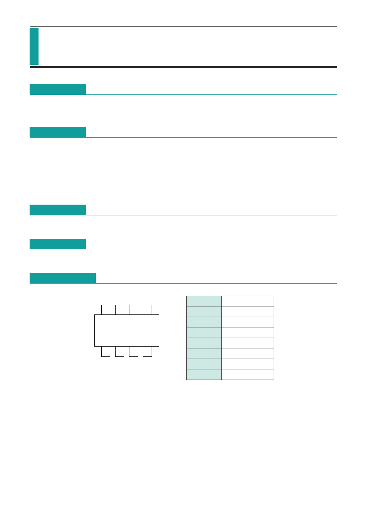
Package
VSOP-8B
Applications
IC for double-protection of lithium-ion batteries with one to three cells.
Pin Assignment
1 V3
2 V2
3 V1
4 GND
5 Ct
6 N.C
7 OUT
8 V
CC
Page 2
MITSUMI
MITSUMI
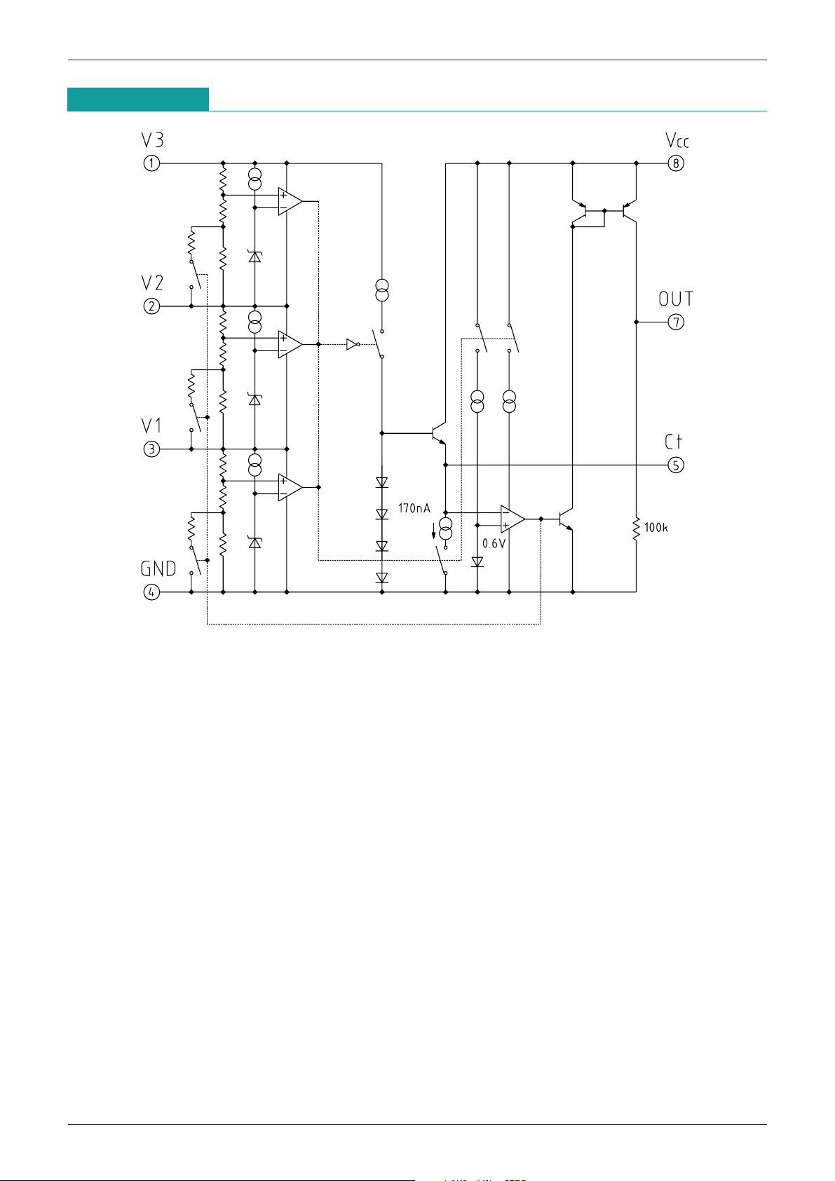
Block Diagram
Protection of Lithium-Ion Batteries (for Double-Protect) MM1451
Page 3
MITSUMI
Protection of Lithium-Ion Batteries (for Double-Protect) MM1451
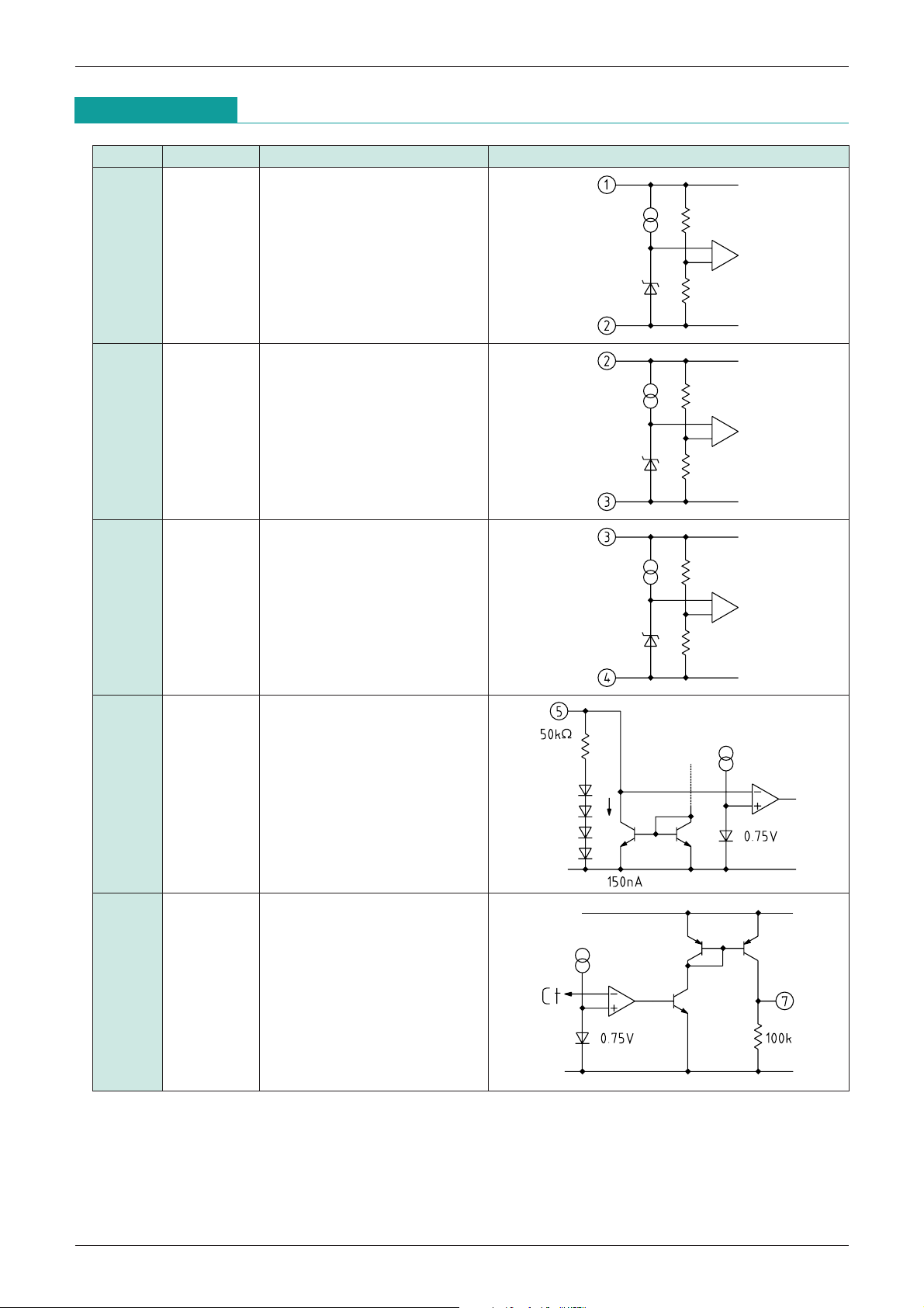
Pin Description
Pin No. Pin name Functions Equivalent circuit diagram
1 V3 3-cell power supply
2 V2 2-cell power supply
3 V1 1-cell power supply
5 Ct Delay capacity pin
7 OUT OUT pin
Page 4

MITSUMI
Protection of Lithium-Ion Batteries (for Double-Protect) MM1451
Absolute Maximun Ratings
Item Symbol Ratings Unit
Operating temparature T
Storage temparature T
V
CC Input voltage VCC
V1 Input voltage *1 V1
V2 Input voltage
V3 Input voltage
Ct pin voltage
V
OUT pin voltage VOUT
1 V2
*
1 V3
*
2 VCT
*
Allowable loss Pd 170 mW
>
>
Note 1 : *1 18V
Note 2 :
2 Do not impress current of 300µA or more on the Ct pin.
*
V3
=
>
V2
=
=
Electrical Characteristics 1
Item Symbol Measurement conditions Min. Typ. Max. Unit
(Ta=25°C)
OPR
STG
>
-
V1
0.3
=
(Except where noted otherwise, Ta=25°C, V
-
20~+80 °C
-
40~+125 °C
-
0.3~18 V
-
0.3~18 V
-
0.3~18 V
CEL
=V3-V2=V2-V1=V1-GND, VCC=3 V
CEL
)
Current consumption 1 I
Current consumption 2 I
Pin I/O current between cells I
Overcharge detection voltage
VS VCEL=L H Ta=-20~+70°C 4.400 4.450 4.500 V
Hysterisis voltage Hys V
Overcharge detection delay time
Output current I
TPLH Ct=0.22µF 1.0 1.5 2.0 S
OH VCEL=VCC=4.5V VO=3V 100 500 µA
Electrical Characteristics 2
Item Symbol Measurement conditions Min. Typ. Max. Unit
Current consumption 1 I
Current consumption 2 I
Pin I/O current between cells I
Overcharge detection voltage
Hysterisis voltage Hys V
Overcharge detection delay time
VS VCEL=L H Ta=-20~+70°C 4.400 4.450 4.500 V
TPLH Ct=0.22µF 1.0 1.5 2.0 S
1 VCEL=3.8V 3.0 6.0 µA
2 VCEL=2.3V 0.3 0.5 µA
3 VCEL=3.8V (between V3, V2, V1) ±0.0 ±0.3 µA
CEL=L H L 35 50 65 mV
(Except where noted otherwise, Ta=25°C, V
1 VCEL=3.8V, VCC=VCEL 3 3.0 6.0 µA
2 VCEL=2.3V, VCC=VCEL 3 0.3 0.5 µA
3 VCEL=3.8V (between V3, V2, V1) ±0.0 ±0.3 µA
CEL=L H L 35 50 65 mV
CEL
=V3-V2=V2-V1=V1-GND, VCC=3 V
CEL
)
Output current I
Output leakage current I
OH VCEL=VCC=4.6V VO=3V 100 500 µA
LEAK VCEL=3.8V, VCC=18V 0.1 µA
Page 5

MITSUMI
MITSUMI
Protection of Lithium-Ion Batteries (for Double-Protect) MM1451
Electrical Characteristics 3
Item Symbol Measurement conditions Min. Typ. Max. Unit
Current consumption 1 I
Current consumption 2 I
Current consumption 3 I
Current consumption 4 I
Pin I/O current between cells I
Overcharge detection voltage
VS VCEL=L H Ta=-20~+70°C 4.400 4.450 4.500 V
Hysterisis voltage Hys V
Overcharge detection delay time
Output current I
Output leakage current I
TPLH Ct=0.22µF 1.0 1.5 2.0 S
OH VCEL=VCC=4.6V VO=3V 100 500 µA
LEAK VCEL=3.8V, VCC=18V 0.1 µA
Measuring Circuit
(Except where noted otherwise, Ta=25°C, V
1 VCEL=3.8V, VCC=VCEL 3 2.5 3.5 µA
2 VCEL=3.8V, VCC=VCEL 3 1.5 2.5 µA
3 VCEL=2.3V, VCC=VCEL 3 0.15 0.3 µA
4 VCEL=2.3V, VCC=VCEL 3 0.1 0.2 µA
3 VCEL=3.8V (between V3, V2, V1) ±0.0 ±0.3 µA
CEL=L H L 35 50 65 mV
CEL
=V3-V2=V2-V1=V1-GND, VCC=3 V
CEL
)
Page 6

MITSUMI
4.45V
4.40V
1.5S
1.8V
0.6V
OUT
(at Ct short)
(at Ct open)
OUT
Ct
V1~V3
MITSUMI
Application Circuit
Delay time Td(S) = 7 CCt (µF)
Protection of Lithium-Ion Batteries (for Double-Protect) MM1451
Note 1: Can support 1, 2 or 3 cells by shorting each cell. However, be sure to connect a battery for V3 cell.
V3 cell may not operate correctly when shorted.
Note 2: When connecting batteries, be sure to connect in the following order: GND V3, and V
V2.
Note 3: Output may go ON momentarily when starting up power supply. If this error output during startup
becomes a problem, connect the V
Note 4: Operation can not be guaranteed for connections other than the above.
CC pin last.
Timing Chart
CC V1OR
Note: Output goes low simultaneously with overcharge detection at Ct pin short and open.
Page 7

MITSUMI
Input voltage (No delay) (V)
6
5
4
3
2
1
0
01234.400 4.450
Output voltage (V)
Temperature (°C)
2.5
3.0
2.0
1.5
1.0
0.5
0.0
-
25 25 75
2200p pm2200ppm
-
500p pm
-
500ppm
Delay time (S)
5
6
4
3
2
1
0
0 0.5 1 1.5 2 2.5 3 3.5 4 4.5
Cell voltage (V)
Consumption
current (µA)
Cell voltage (V)
0.2
0.3
0.1
0
-
0.1
-
0.2
-
0.3
0 0.5 1 1.5 2 2.5 3 3.5 4 4.5
Pin I/O current
between cells (µA)
Protection of Lithium-Ion Batteries (for Double-Protect) MM1451
Characteristics
Detection voltage Output delay time
Consumption current
Pin I/O current between cells
 Loading...