

Page 1
INFRARED RECEIVER MODULE
MIM-R1AA38
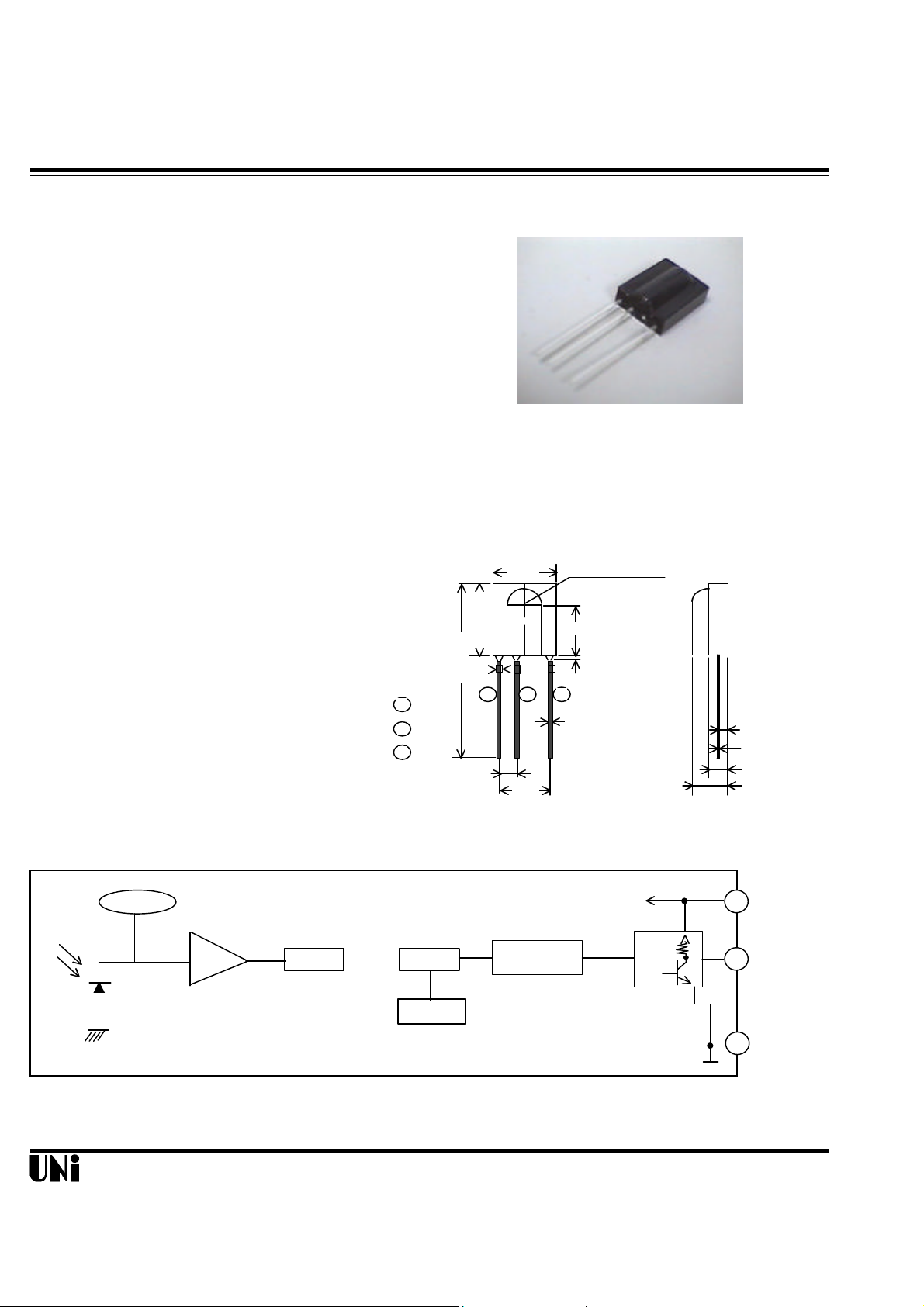
Description Package Dimensions
Output
ABLC
fo setting
1
30.6±0.5
1.4±0.3
0.4±0.050
12.5±0.4
7.62
2.54
5.8±0.3
10±0.3
23231
The MIM-R1AA38 series are 37.9 KHZ miniaturized
infrared receivers for remote control and other
appplications requiring improved ambient light rejection.
The separate PIN diode and preamplifier IC are
assembled on a single leadframe.
The epoxy package contains a special IR filter.
This module has excellent performance even in disturbed
ambient light applications and provides protection
against uncontrolled output pulses.
Features
l Photo detector and preamplifier in one package
l Internal filter for PCM frequency
l High immunity against ambient light
l Improved shielding against electric field disturbance
l 5-Volt supply voltage; low power consumption
l TTL and CMOS compatibility
MIM-R1AA38
9.2±0.5
Unit: mm
CENTER OF SENSOR
BLOCK DIAGRAM
GND
Vcc
Vout
TRAP BPF
0.65
Notes :
1. Tolerance is ± 0.25 mm (.010") unless otherwise noted.
2. Lead spacing is measured where the leads emerge from the package.
0.8max.
0.5±0.050
V
TRIMMING
GND
S
Unity Opto Technology Co., Ltd.
P1
Page 2
MIM-R1AA38
Absolute Maximum Ratings
CC
opr
stg
sd
@ T
=25°C
@ TA=25°C
600µs
600µs
10
µ
F
PD3516
out
Item Symbol Ratings Unit Remark
Supply voltage V
Operating temperature T
Storage temperature T
Soldering temperature T
5.8 V
-10 ~ + 60 °C
-20 ~ + 75 °C
260 °C Maximum 5 seconds
Electro-optical characteristics (VCC=5V)
Parameter Symbol Min. Typ. Max. Unit Remarks
Current consumption Icc 5.0 mA Under no signal
Response wavelength p 940 nm
Tuning frequency
f
0
37.9
KH
Z
Output form - - - - - active low output - - - - -
H level output voltage V0h 4.2 V
L level output voltage V0l 0.5 V
H level output pulse width Twh 400 800
L level output pulse width Twl 400 800
Distance between emitter &detector
L 10.0 m Note 1
s
s
Half angle ±16 ±55 deg Horizonal direction
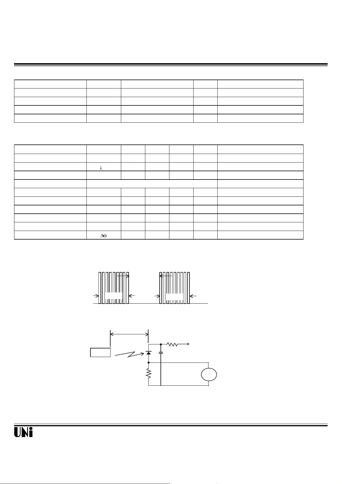
Test Method
A. Standard Transmitter
ON/OFF pulse width satisfied from 20 cm to detection limit
carrier frequency f
duty 50%
Unity Opto Technology Co., Ltd.
0
600µs
Fig 1.Burst Wave
20cm
10kΩ
Transmitter
Duty 50%
Ω
10k
Fig 2.Standard Transmitter Measurement circuit
+5v
V
Oscilloscope
P2
Page 3

MIM-R1AA38
B. Detection Length Test
D.U.T
L
θ
: indicates horizontal and vertical directions
600µs
600µs
Transmitter output
C. Pulse Width Test
Transmitter output
DUT output pulse
Twl
V
out
V0h
V0l
Twh
CHARACTERISTIC CURVES (TA=25°C)
2.8
2.7
2.6
2.4
Supply Current Icc (mA)
2.2
2.0
3 4 5 6 7
2
Supply Voltage Vcc (V)
8
SUPPLY VOLTAGE vs. SUPPLY CURRENT
NOTE 1. Distance between emitter & detector specifies maximum distance that output wave form satisfies
the standard under the conditions below against the standerd transmitter.
(1)Measuring place ………Indoor without extreme reflection of light.
(2)Ambient light source… Detecting surface illumination shall be 200±50Lux under ordinary
hite fluorescense lamp of no high frequency lighting.
(3)Standard transmitter … Burst wave indicated in Fig 1. of standard transmitter
shall be arranged to 50mVp-p under the measuring circuit
specified in Fig 2.
900
s)
µ
(
800
PW
700
600
Output Pulse Width t
500
400
0.1 1 10 100
INPUT LEVEL vs.OUTPUT PULSE WIDTH
Burst length * 600µs, cycle = 1.2ms
tpw: Average value of output from start
of signal input to 60th pulse
Input Level VIN (mV
Input Level (mV
)
P-P
)
p-p
1000
Unity Opto Technology Co., Ltd.
P3
 Loading...