

Page 1
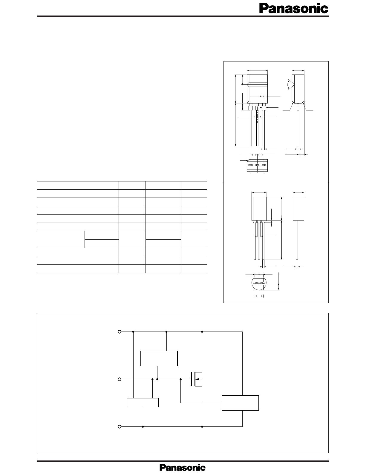
Intelligent P ower Devices (IPDs) MIP501, MIP502
5.0±0.2
13.5±0.5
0.7±0.2
8.0±0.2
1.27
123
1.27
4.0±0.2
0.45
+0.15
-
0.1
0.45
+0.15
-
0.1
2.3±0.2
0.7±0.1
2.54±0.15
MIP501, MIP502
Silicon MOS IC
■ Features
●
High breakdown voltage, N-Ch MOS FET output
(V
> 40V Ron < 0.5Ω)
DSS
●
Over-current-protection function built-in
●
Reset function built-in
●
Direct drive possible by the logic circuit
■ Applications
●
Lamp drive
■
Absolute Maximum Ratings (Ta= 25˚C)
Parameter
Output breakdown voltage
Output peak current
Output current
Input voltage
Input current
Allowable power
dissipation
MIP501
MIP502
Junction temperature
Storage temperature
Operating temperature
Symbol
V
DSS
I
OP
I
OA
V
IN
I
IN
P
D
T
j
T
stg
T
opr
Rating
40
5
1.7
– 0.5 to 6
±10
1.5
*
1
150
– 55 to +150
– 40 to + 85
Unit
V
A
A
V
mA
W
˚C
˚C
˚C
* The value at mounted on PCB (glass epoxy resin: 100 ×100mm). (For MIP502 only)
■ Block Diagram
MIP501 Unit : mm
7.5±0.2 4.5±0.2
3.8±0.2
10.8±0.216.0±1.0
2.5±0.1
0.65±0.1
0.8C
0.85±0.10.65±0.1
1.0±0.1
0.7±0.1
0.5±0.1
2.5±0.22.5±0.2
90°
0.8C
0.4±0.1
2.05±0.2
0.8C
1 : IN
2 : Drain
123
3 : Source
MT3 Type Package
MIP502 Unit : mm
1 : Source
2 : Drain
3 : IN
TO-92NL T ype Packa ge
2
DRAIN
Over voltage
3
IN
1
SOURCE
protection circuit
Reset circuit
Over current
protection circuit
Page 2

Intelligent P ower Devices (IPDs) MIP501, MIP502
■ Pin Descriptions
No.1 pin : GND pin. Connect to the GND pin. (Source)
No.2 pin : Output pin. Connect to the load. The current flowing into this terminal is limited at about 5A. When this termi-
nal voltage exceeds about 4.6V, the output MOS FET is turned OFF. (Drain)
No.3 pin : Input pin. The signal from the logic is inputted to drive the de vice. W hen this is open, the output MOS FET turns
OFF.
■
Electrical Characteristics (Ta= 25˚C)
Parameter
Drain-Source ON-resistance
Drain voltage
Drain breakdown voltage
Drain leakage current (1)
Drain leakage current (2)
Input voltage
Over-current protection
Reset voltage
Input current
Symbol
R
DS (ON)
V
DS (ON)
V
DSS
I
DSS (1)
I
DSS (2)
V
IN (H)
V
IN (L)
I
OCP
V
RESET
I
IN (opr)
= 5V, IO=1.5A
V
IN
= 5V, IO=1.5A
V
IN
= 3mA
I
DSS
V
DSS
V
DSS
= 5V
V
IN
= 5V
V
IN
= 5V, V
V
IN
= 40V
= 25V
Condition
=1V
DS
Min
40
4.5
Typ
5.0
5.0
4.6
Max
0.5
0.75
3.0
1.5
6.0
0.8
1.0
Unit
Ω
V
V
mA
mA
V
V
A
V
mA
Page 3
Intelligent P ower Devices (IPDs) MIP501, MIP502
SS
N
SS
V
100
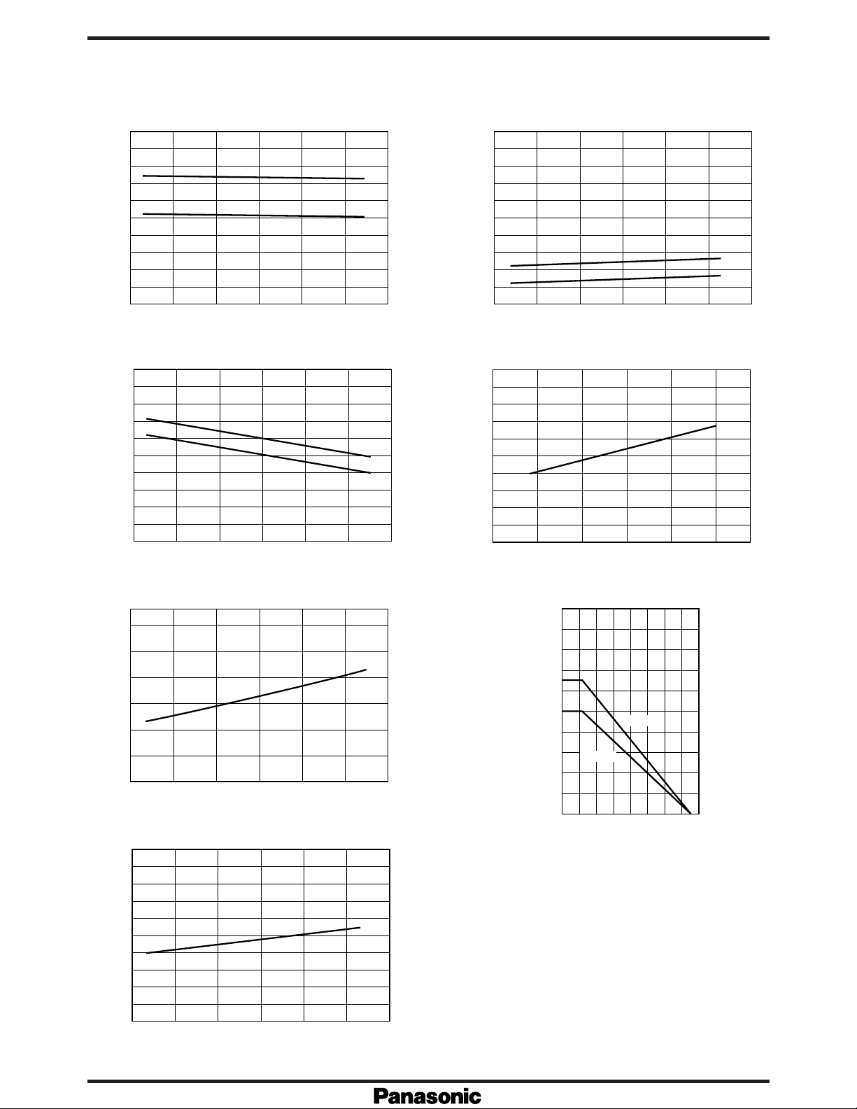
– Ta I
DSS
5
DSS
– Ta
(V)
DSS
80
60
40
20
Output breakdown voltage V
0
-50 0 50
Ambient temperature Ta (˚C)
Is – Ta IIN –V
10
8
6
4
2
Detected value at over current Is (˚C)
0
-50 0 50
Ambient temperature Ta (˚C)
MIP502
MIP501
(mA)
4
DSS
3
2
1
Output leakage current I
100
0
-50 0 50 100
Ambient temperature Ta (˚C)
IN
100
(µA)
=3V
V
DS
=2V
V
DS
100
IN
50
Input current I
0
456
Input voltage V
(V)
IN
Ron – Ta PD – Ta
0.6
(Ω)
on
0.4
0.2
ON-resistance R
0
-50 0 50 100
100
80
(µA)
IN
60
40
Input current I
20
Ambient temperature Ta (˚C)
I
IN
– Ta
2.0
1.8
1.6
(W)
D
1.4
1.2
1.0
0.8
0.6
Allowable drain loss P
0.4
0.2
MIP502
0
0
40 80
Ambient temperature Ta (˚C)
MIP501
120 160
0
-50 0 50 100
Ambient temperature Ta (˚C)
 Loading...