

Page 1

www.fairchildsemi.com
User Guide for
AN-8026: FAN9611 / FAN9612 400W
1-Layer Evaluation Board (FEB-301)
Featured Fairchild Product:
FAN9611 / FAN9612
Direct questions or comments
about this Evaluation Board to:
“Worldwide Direct Support”
Fairchild Semiconductor.com
© 2009 Fairchild Semiconductor Corporation AN-8026 / FEB301_FAN9611 / FAN9612 • Rev. 0.0.4
Page 2

www.fairchildsemi.com
Table of Contents
1.Overview of the Evaluation Board ............................................................................................. 3
2.General Specification .................................................................................................................. 3
3.Test Procedures ........................................................................................................................... 4
4.Schematic .................................................................................................................................... 6
5.Specification Approval ............................................................................................................... 7
6.Boost Inductor Specification ...................................................................................................... 9
6.1. Electrical Specification ............................................................................................... 10
7.Bill of Materials ........................................................................................................................ 12
8.Test Results ............................................................................................................................... 16
8.1. Startup ......................................................................................................................... 16
8.2. Normal Operation ....................................................................................................... 17
8.3. Line and Load Transient ............................................................................................. 18
8.4. Brown in/out Protection ............................................................................................. 19
8.5. Phase Management ..................................................................................................... 20
8.6. Efficiency.................................................................................................................... 21
8.7. Harmonic Distortion and Power Factor ...................................................................... 22
9.References ................................................................................................................................. 24
© 2009 Fairchild Semiconductor Corporation 2 AN-8026 / FEB301_FAN9611 / FAN9612 • Rev. 0.0.4
Page 3
www.fairchildsemi.com
The following user guide supports the FAN9611 / FAN9612 400W evaluation board for
interleaved boundary-conduction mode power factor corrected supply. The user guide
should be used in conjunction with the FAN9611/FAN9611 / FAN9612 datasheet as well
as the Fairchild application note AN-6086 — Design Considerations for Interleaved
Boundary-Conduction Mode PFC Using FAN9611 / FAN9612. The user guide and the
evaluation board can also be used to evaluate FAN9611 controller which has the lower
turn-on threshold. Please visit Fairchild’s website at www.fairchildsemi.com
information.
1. Overview of the Evaluation Board
The FAN9611 / FAN9612 interleaved dual Boundary-Conduction-Mode (BCM) PowerFactor-Correction (PFC) controller operates two parallel-connected boost power trains
180º out of phase. Interleaving extends the maximum practical power level of the control
technique from about 300W to greater than 800W. Unlike the continuous conduction
mode (CCM) technique often used at higher power levels, BCM offers inherent zerocurrent switching of the boost diodes (no reverse-recovery losses), which permits the use
of less expensive diodes without sacrificing efficiency. Furthermore, the input and output
filters can be smaller due to ripple current cancellation between the power trains and
effectively doubling the switching frequency.
The advanced line feedforward with peak detection circuit minimizes the output voltage
variation during line transients. To guarantee stable operation with less switching loss at
light load, the maximum switching frequency is clamped at 600kHz. Synchronization is
maintained under all operating conditions.
for
Built-in protection functions include output over-voltage, over-current, open-feedback,
under-voltage lockout, brownout, and redundant latching over-voltage. The FAN9611 /
FAN9612 is available in a lead-free 16-lead SOIC package.
Fairchild offers and evaluation board to aide in design and test of applications using the
FAN9611 / FAN9612. The FAN9611 / FAN9612 evaluation board is a single-layer board
designed for 400W (400V/1A) rated power. Thanks to the phase management, the
efficiency is maintained above 95% at low-line and high-line, even down to 10% of the
rated output power. The efficiencies for full-load condition are 96.3% and 98.0% at line
voltages of 115V
and 230VAC, respectively.
AC
2. General Specification
Specification Min. Max. Units
Input
VIN AC Voltage 90 264 VAC
VIN AC Frequency 47 63 Hz
VDD Supply 13 16 VDC
Output
Output Voltage 400 V
Output Current 1 A
Total Output Power
Maximum Load Output Power 400 W
© 2009 Fairchild Semiconductor Corporation 3 AN-8026 / FEB301_FAN9611 / FAN9612 • Rev. 0.0.4
Page 4
www.fairchildsemi.com
3. Test Procedures
Before testing the board; DC voltage supply for VDD, AC voltage supply for line input,
and DC electric load for output should be connected to the board properly.
1. Supply V
specification for V
2. When V
the inrush current limit relay is turned on by 5V reference (pin #3), the relay turns on
when FAN9611 / FAN9612 comes out of UVLO by supplying V
3. Connect the AC voltage (90~264V
FAN9611 / FAN9612 has brownout protection and line OVP, any input voltages out
of operation range trigger protections.
4. Change load current (0~1A) and check the operation. The board is designed to go
into phase shedding for output power below around 55W. It goes back to twochannel interleaving operation for output power above around 110W.
Table 1. Test Equipment
Test Model
Test Date
Test Temperature
Test Equipment
Test Items
for the control chip first. It should be higher than 13V (refer to the
DD
turn-on threshold voltage).
DD
is supplied, a "click" sound from the relay is heard. This is normal. Since
DD
FEB301-001
Sept.7, 2009
Ambient
AC Source: Chroma 61603 AC POWER SOURCE
Electronic Load: Chroma 63108
Power Meter: WT210
Oscilloscope: Lecroy wavesurfer 24Xs
DC Source: ABM 9306D
Startup
Normal Operation
Normal Operation
Line and Load Transient
Brown in/out Protection
Phase Management
Efficiency
Harmonic Distortion and Power Factor
higher than 13V.
DD
) to start the FAN9611 / FAN9612. Since
AC
© 2009 Fairchild Semiconductor Corporation 4 AN-8026 / FEB301_FAN9611 / FAN9612 • Rev. 0.0.4
Page 5
www.fairchildsemi.com
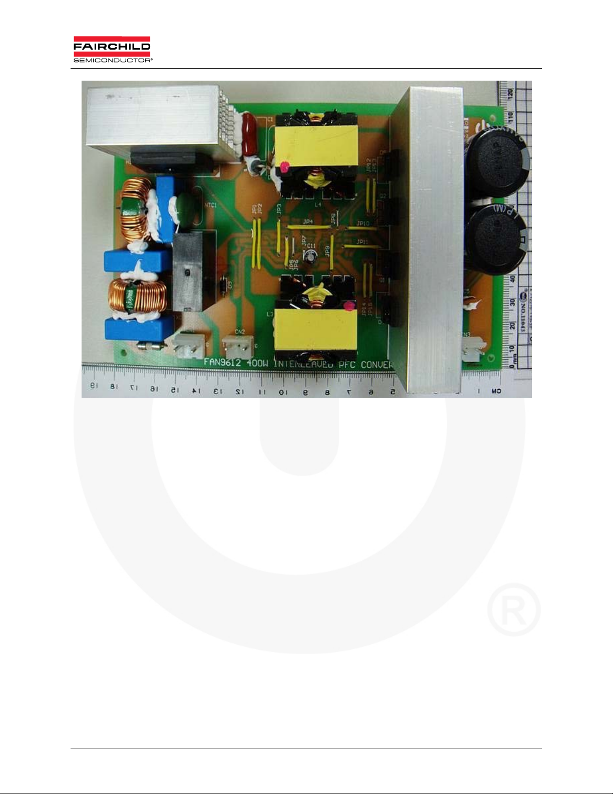
Figure 1. Photograph of Tested Board
© 2009 Fairchild Semiconductor Corporation 5 AN-8026 / FEB301_FAN9611 / FAN9612 • Rev. 0.0.4
Page 6
www.fairchildsemi.com
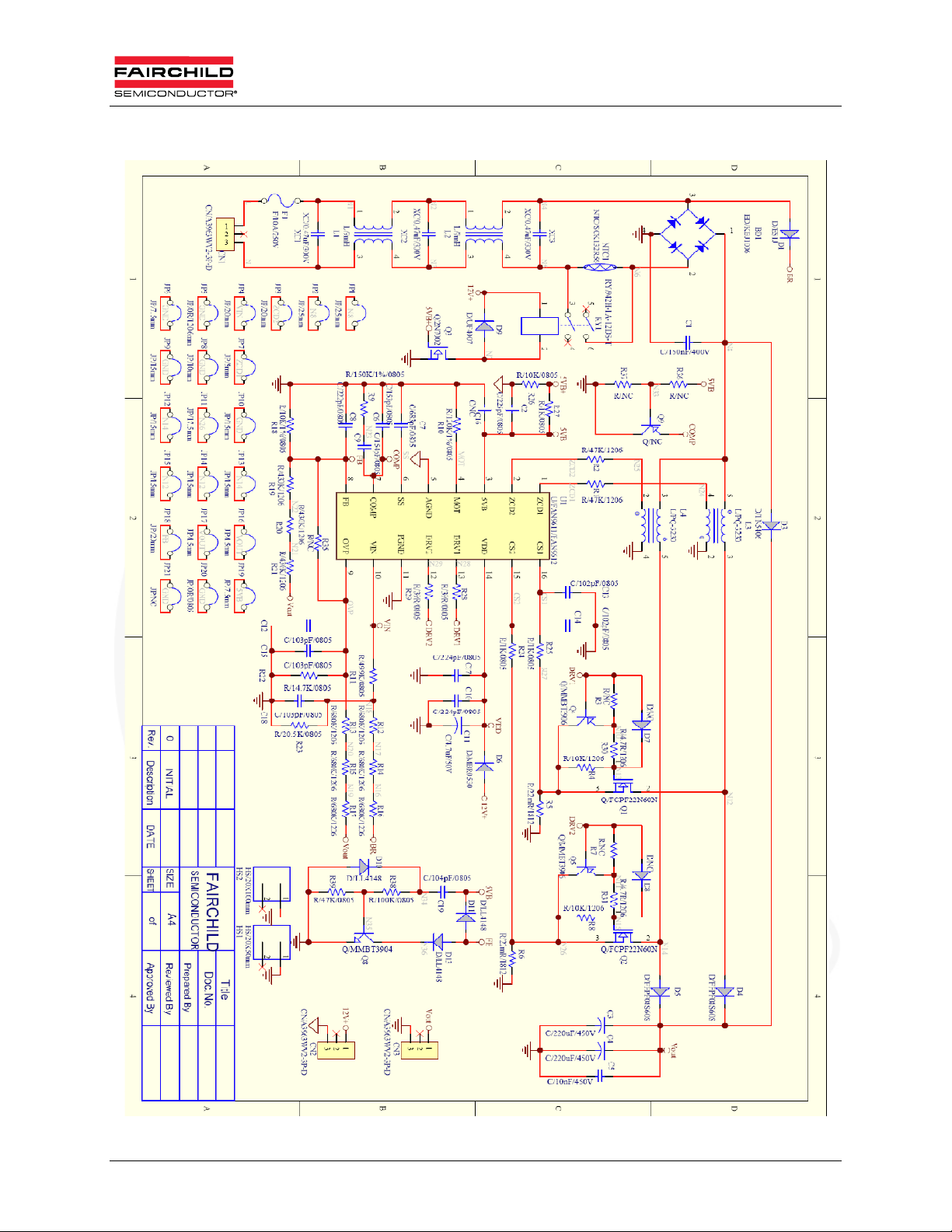
4. Schematic
Figure 2. FAN9611 / FAN9612 400W Evaluation Board Schematic
© 2009 Fairchild Semiconductor Corporation 6 AN-8026 / FEB301_FAN9611 / FAN9612 • Rev. 0.0.4
Page 7
www.fairchildsemi.com
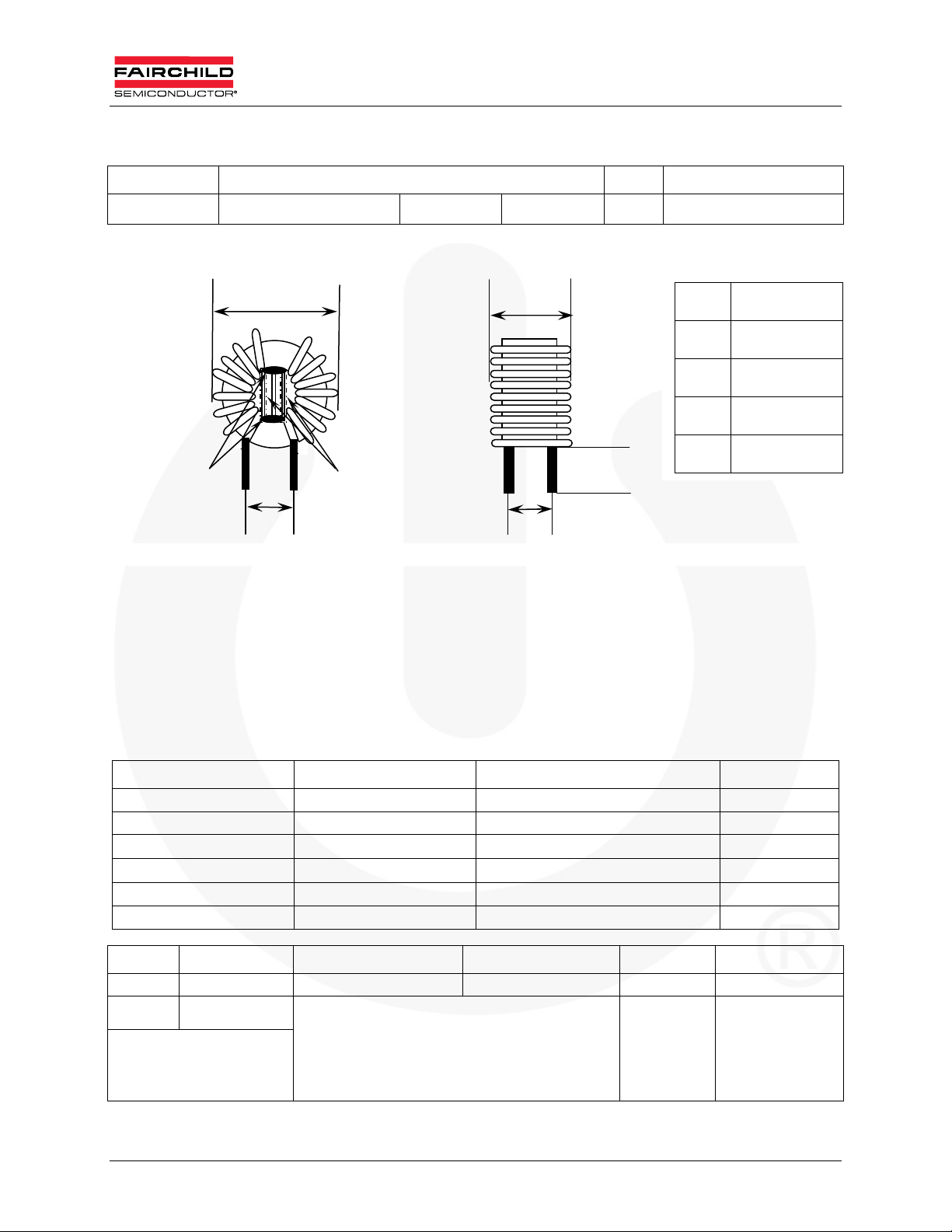
5. Specification Approval
Customer Fairchild Semiconductor P/N: TRN-0197
Date 08/04/2006 Version A Page 1/1
Dimension Unit: mm
A B
Black Glue E
tube
C D
Middle partition board thickness of 2mm
(Safety Regulation)
A 30 max
B 5 max
C 11 ref
D 13 ref
E
151
Electrical Specification: 1kHz 1V
Inductance:L1=L2:9.0mH minimum
DC Resistance: L1=L2:0.05 maximum
Turn and Wire: L1=L2:0.9 x 30.5TSx2
Materials List:
Component Material Manufacturer UL File #
1. CORE T22x14x08 TOMITA
2. WIRE THFN-216 Ta Ya Electric Wire Co., Ltd. E197768
UEWN/U
UEWE
UWY Jang Shing Wire Co., Ltd. E174837
3. Solder 96.5% Sn,3% Ag,0.5% Cu, Xin Yuan Co., Ltd.
Unit m/m Drawn Check Title
TEL (02)29450588 Ci wun Chen Guo long Huang IDENT#. TRN-0197
FAX (02)29447647
No.26-1, Lane 128, Sec. 2,
Singnan Rd., Jhonghe City,
Taipei County 235, Taiwan
(R.O.C.)
SEN HUEI INDUSTRIAL CO.,LTD. D W G# I0060
PACIFIC Wire Cable Co., Ltd.
Tai-l Electric Wire Cable Co., Ltd.
E201757
E85640
© 2009 Fairchild Semiconductor Corporation 7 AN-8026 / FEB301_FAN9611 / FAN9612 • Rev. 0.0.4
Page 8
www.fairchildsemi.com
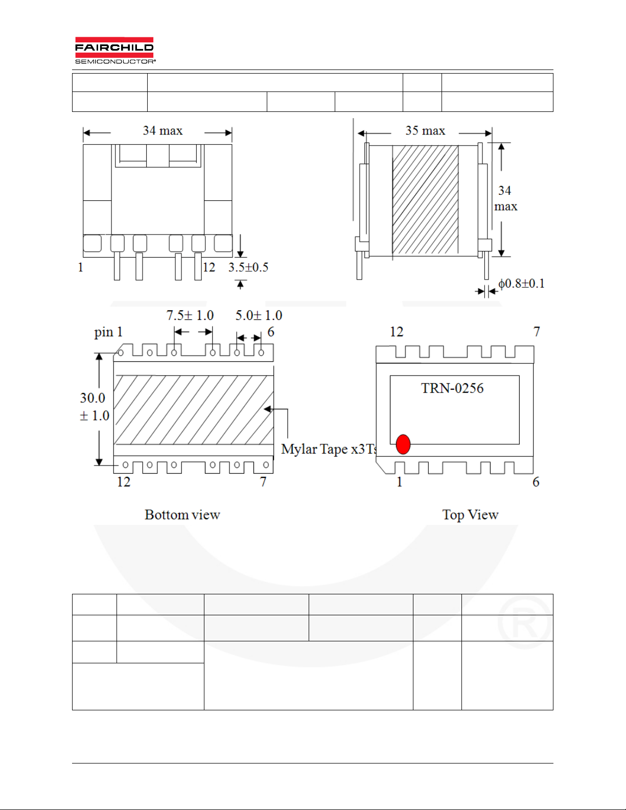
Customer Fairchild Semiconductor P/N: TRN-0256
Date 09/02/2009 Version A Page 1/4
Notes:
1. Pin 1,6,7,8,10,11,12 removed.
2. Add insulation tape *3 turns to fix core and bobbin.
3. The red symbol indicates first pin.
Unit m/m Drawn Check Title
TEL (02)2 945-0588 Ci wun Chen Guo long Huang IDENT# TRN-0256
FAX (02)2944-7647
No.26-1, Lane 128, Sec. 2,
Singnan Rd., Jhonghe City,
Taipei County 235, Taiwan
(R.O.C.)
© 2009 Fairchild Semiconductor Corporation 8 AN-8026 / FEB301_FAN9611 / FAN9612 • Rev. 0.0.4
SEN HUEI INDUSTRIAL CO.,LTD. D W G# I3205
Page 9

www.fairchildsemi.com
Customer Fairchild Semiconductor P/N: TRN-0256
Date 09/02/2009 Version A Page 3/4
6. Boost Inductor Specification
Figure 3. Boost Inductor in the FAN9611 / FAN9612 Evaluation Board
Note:
1. Pins 2, 4, 5 add tube.
Unit m/m Drawn Check Title
TEL (02)2945-0588 Ci wun Chen Guo long Huang IDENT# TRN-0256
FAX (02)2944-7647
No.26-1, Lane 128, Sec. 2,
Singnan Rd., Jhonghe City,
Taipei County 235, Taiwan
(R.O.C.)
SEN HUEI INDUSTRIAL CO.,LTD. D W G# I3205
© 2009 Fairchild Semiconductor Corporation 9 AN-8026 / FEB301_FAN9611 / FAN9612 • Rev. 0.0.4
Page 10

www.fairchildsemi.com
6.1. Electrical Specification
Inductance Test: at 1kHz, 1V
P(5-3): 200µH 5%
DC Resistance test at TA = 25°C
P(5-3): 62.44m maximum
P(2-4): 196.7m maximum
Hi-Pot Test:
AC 1000V / 60Hz / 0.5mA hi-pot for one minute between pri to sec
AC 500V / 60Hz/ 0.5mA hi-pot for one minute between pri to core
Insulation Test:
The insulation resistance is between pri to sec and windings to core measured by DC
500V
Must be over 100M
Terminal Strength:
Kg on terminals for 30 seconds, test the breakdown
UNIT m/m DRAWN CHECK TITLE
TEL (02)2945-0588 Ci wun Chen Guo long Huang IDENT# TRN-0256
FAX (02)2944-7647
No.26-1, Lane 128, Sec. 2,
Singnan Rd., Jhonghe City,
Taipei County 235, Taiwan
(R.O.C.)
SEN HUEI INDUSTRIAL CO.,LTD. D W G# I3205
© 2009 Fairchild Semiconductor Corporation 10 AN-8026 / FEB301_FAN9611 / FAN9612 • Rev. 0.0.4
Page 11

www.fairchildsemi.com
Customer Fairchild Semiconductor P/N: TRN-0256
Date 09/02/2009 Version A Page 3/4
Materials List:
Component Material Manufacturer File#
1.Bobbin
2.Core MB4 Ferrite Core PQ3230
3.Wire
4.Varnish
5.Tape
0.025tmm
6.Tube
7.Terminals
Phenolic
94v-0,T373J,150°C
UEWE
130°C
UEW-2
130°C
UEW-B
130°C
BC-346A
180°C
468-2FC
130°C
Polyester 3M
#1350 130°C
#31CT 130°C Nitto Denko Corp.
Teflon tube
TFS
600V,200°C
Tin coated-
Copper wire
PQ3230
Chang Chun Plastics Co., Ltd.
Tai-I Electric Wire & Cable Co., Ltd.
Jung Shing Wire Co., Ltd. E174837
Chuen Yih wire co., Ltd.
John C Dolph Co., Ltd.
Ripley Resin Engineering Co., Inc.
Minnesota mining &MFG Co., Ltd.
Great Holding Industrial Co., Ltd.
Will Fore Special Wire Corp.
E59481(S)
E85640﹙S﹚
E154709﹙S﹚
E51047﹙M﹚
E81777﹙N﹚
E17385﹙N﹚
E34833﹙M﹚
E156256﹙S﹚
Unit m/m Drawn Check Title
TEL (02)2945-0588 Ci wun Chen Guo long Huan g IDENT# TRN-0256
FAX (02)2944-7647
No.26-1, Lane 128, Sec. 2,
Singnan Rd., Jhonghe City,
Taipei County 235, Taiwan
(R.O.C.)
SEN HUEI INDUSTRIAL CO.,LTD. D W G# I3205
© 2009 Fairchild Semiconductor Corporation 11 AN-8026 / FEB301_FAN9611 / FAN9612 • Rev. 0.0.4
Page 12

www.fairchildsemi.com
7. Bill of Materials
Component Qty. Part # Reference
JUMPER WIRE 0.8ψ(mm) 18 JP1~ JP4 JP6~JP19
Resistor 0805 0Ω+/-5% 1 JP20
Resistor 0805 39Ω+/-5% 2 R28 R29
Resistor 0805 1KΩ+/-5%
Resistor 0805 14K7Ω +/-1% 1 R22
Resistor 0805 10KΩ+/-1% 2 R18 R26
Resistor 0805 20K5Ω +/-1%
Resistor 0805 47KΩ+/-5% 1 R39
Resistor 0805 49K9Ω +/-1% 1 R11
Resistor 0805 100KΩ+/-5%
Resistor 0805 120KΩ+/-1% 1 R10
Resistor 0805 150KΩ+/-1% 1 R9
Resistor 1206 0Ω+/-5% 1 JP5
3 R24 R25 R27
1 R23
1 R38
Resistor 1206 4Ω7+/-5% 2 R30 R31
Resistor 1206 10KΩ+/-5% 2 R4 R8
Resistor 1206 47KΩ+/-5% 2 R1 R2
Resistor 1206 430KΩ+/-5% 3 R19 R20 R21
Resistor 1206 680KΩ+/-5% 6 R12~R17
NTC13ψ 2Ω SCK132 1 NTC1
Resistor 1812 0Ω022 +/-5% 2 R5 R6
0805 MLCC X7R +/-10% 102P 50V 2 C13 C14
0805 MLCC X7R +/-10% 103P 50V 3 C12 C15 C18
0805 MLCC X7R +/-10% 473P 50V 1 C19
0805 MLCC X7R +/-10% 104P 50V 1 C6
0805 MLCC X7R +/-10% 154P 25V 1 C9
0805 MLCC X7R +/-10% 222P 50V 1 C8
0805 MLCC X7R +/-10% 224P 50V 2 C10 C17
0805 MLCC X7R +/-10% 225P 25V 1 C2
0805 MLCC X7R +/-10% 683P 50V 1 C7
© 2009 Fairchild Semiconductor Corporation 12 AN-8026 / FEB301_FAN9611 / FAN9612 • Rev. 0.0.4
Page 13

www.fairchildsemi.com
Bill of Materials (Continued)
Component Qty. Part # Manufacturer Reference
Ceramic Capacitor 103P 500V +80/-20% 1 C5
Electrolytic Capacitor 47µ 50V 105°C 1 LHK JACKCON C11
Electrolytic Capacitor 220µF 450V 105°C 2 LKP JACKCON C3 C4
MPP Capacitor 0.15µF 400V ±5% 1 MPP154J2G15 ALL-RISE C1
X1 Capacitor 0.47µ 300V +/-10% 3
Common Mode Choke 2 TRN0197 SEN HUEI L1 L2
Custom Inductor PQ3230 L=200µH 2 TRN0256 SEN HUEI L3 L4
Rectifier 3A/600V DO-201AD 1 1N5406 Fairchild Semiconductor D3
Ultra Fast Recovery Rectifier 1A/600V 1 ES1J Fairchild Semiconductor D1
Ultra Fast Diode 1A/1000V DO-41 1 UF 4007 Fairchild Semiconductor D9
SMD Diode LL4148 4 D7 D8 D10 D13
Bridge 10A/600V 1 KBJ1006 CP BD1
SX1-S4741K300S1
SHINY XC1 XC2 XC3
SMD Schottky Rectifiers 0.5A/30V SOD-123 1 MBR0530 Fairchild Semiconductor D6
Rectifier 8A/600V TO-220F 2 FFPF08S60S Fairchild Semiconductor D4 D5
MOSFET N-CH 300mA/60V 1 2N7002 Fairchild Semiconductor Q3
SMD NPN Amplifier 1 MMBT3904 Fairchild Semiconductor Q8
SMD PNP Amplifier 2 MMBT3906 Fairchild Semiconductor Q4 Q5
MOS 18A/500V TO-220F 2 FDPF18N50 Fairchild Semiconductor Q1 Q2
FUSE CERAMIC 250V10A SLOW 1 37SG SLEEK F1
RELAY 942H-1A-12DS-T 1 BRIGHT TOWARD RY1
WAFER(8639HS) 3-1P 3.96mm180° 3 CN1 CN2 CN3
HS 50(L)*50(H)*20(W)mm 1 MCH0597 SHUN TEH HS1
HS 100(L)*50(H)*20(W)mm 1 MCH0598 SHUN TEH HS2
IC FAN9611 / FAN9612 SMD 1 SOIC-16 Fairchild Semiconductor U1
PCB FCS0390 REV 4 1 Fairchild Semiconductor
© 2009 Fairchild Semiconductor Corporation 13 AN-8026 / FEB301_FAN9611 / FAN9612 • Rev. 0.0.4
Page 14

www.fairchildsemi.com
Figure 4. PCB Layout Top Overlay
Figure 5. PCB Layout Bottom Layer
© 2009 Fairchild Semiconductor Corporation 14 AN-8026 / FEB301_FAN9611 / FAN9612 • Rev. 0.0.4
Page 15

www.fairchildsemi.com
Figure 6. PCB Layout Bottom Overlay
© 2009 Fairchild Semiconductor Corporation 15 AN-8026 / FEB301_FAN9611 / FAN9612 • Rev. 0.0.4
Page 16

www.fairchildsemi.com
/
/
/
/
8. Test Results
8.1. Startup
Test Condition: 115V
Figure 7. 115V
/ 60Hz, 230V
AC
AC
/ 50Hz, no load and full load.
AC
60Hz No Load Figure 8. 115V
60Hz Full Load
AC
Note:
2. Only 29V overshoot is observed (7.44% of nominal output voltage) for no-load startup and only 18V (4.62% of
normal output voltage) overshoot is observed for full-load startup.
Figure 9. 230V
50Hz No Load Figure 10.230V
AC
50Hz Full Load
AC
Note:
3. Only 17V overshoot is observed (4.36% of nominal output voltage) for no-load startup and only 18V (4.62% of
normal output voltage) overshoot is observed for full-load startup.
© 2009 Fairchild Semiconductor Corporation 16 AN-8026 / FEB301_FAN9611 / FAN9612 • Rev. 0.0.4
Page 17

www.fairchildsemi.com
/
/
/
/
8.2. Normal Operation
Test Condition: Inductor current of 115VAC / 60Hz, 230VAC / 50Hz full load.
Figure 11. 115V
60Hz Full Load Figure 12.115V
AC
60Hz Full Load
AC
Note:
4. Figure 11 and Figure 12 show the two inductor currents and the sum of two inductor currents at 115V
voltage and full-load conditions. The sum of the inductor currents has relativel y small ri pple due to the ripple
cancellation of interleaving operation.
Figure 13. 230V
50Hz Full Load Figure 14.230V
AC
50Hz Full Load
AC
AC
line
Note:
5. Figure 13 and Figure 14 show the two inductor currents and the sum of two inductor currents at 230V
AC
line
voltage and full-load conditions. The sum of the inductor currents has relativel y small ri pple due to the ripple
cancellation of interleaving operation.
© 2009 Fairchild Semiconductor Corporation 17 AN-8026 / FEB301_FAN9611 / FAN9612 • Rev. 0.0.4
Page 18

www.fairchildsemi.com
8.3. Line and Load Transient
Test Condition: 115VAC to 230VAC full load transient and 230VAC load transient.
Figure 15. 230VAC to 115VAC Line Transient Figure 16.115VACto 230VAC Line Transient
Note:
6. Figure 15 and Figure 16 show the line transient operation and minimal effect on the output voltage due to the line
feed forward function. When the line voltage changes from 230VAC to 115VAC, 14.5V (3.72% of nominal output
voltage) voltage undershoot is observed. When the line voltage changes from 115V
voltage undershoot is observed.
to 230VAC, almost no
AC
Figure 17. 230V
Note:
7. Figure 17 and Figure 18 show the load-transient operation. When the output load chang es from 100% to 0%,
23.6V (6.1% of nominal output voltage) voltage overshoot is observed. When the output load changes from 0%
to 100%, 23.9V (6.13% of nominal output voltage) voltage undershoot is observed.
100% to 0% Line Transient Figure 18.230VAC0% to 100% Line Transient
AC
© 2009 Fairchild Semiconductor Corporation 18 AN-8026 / FEB301_FAN9611 / FAN9612 • Rev. 0.0.4
Page 19

www.fairchildsemi.com
8.4. Brown in/out Protection
Test Condition: startup and shutdown when slowly increasing and decreasing the line voltage.
Figure 19. Brow nin Figure 20.Brownout
Note:
8. Figure 19 and Figure 20 show the startup and shutdown operation at slowl y increasing and decreasing line
voltage, respectively. The power supply starts when the line voltage reaches around 80VAC and shuts down
when line voltage drops below 70V
AC
.
© 2009 Fairchild Semiconductor Corporation 19 AN-8026 / FEB301_FAN9611 / FAN9612 • Rev. 0.0.4
Page 20

www.fairchildsemi.com
A
8.5. Phase Management
Test Condition: Change the output load to observe the phase shedding and addin g.
Figure 21. Phase-Shedding Figure 22.Zoom-In
Note:
9. Figure 21 and Figure 22 show the phase-shedding waveforms. The duty cycle of the channel 1 gate drive signal
is doubled when the other channel gate drive signal is disabled to minimize the line current glitch.
Figure 23. Phase-Adding Figure 24.Zoom-In
Note:
10. Figure 23 and Figure 24 show the phase-adding waveforms. The duty cycle of Channel 1 gate drive signal
becomes half just before the other channel gate drive signal is enabled to minimize the line current glitch.
Figure 25. Phase-Shedding and Line Current Figure 26.Phase-
Note:
11. Figure 25 and Figure 26 show the sum of two-inductor current and line current for phase shedding and adding,
respectively. As shown, the phase management causes no visible change in the line current waveforms.
© 2009 Fairchild Semiconductor Corporation 20 AN-8026 / FEB301_FAN9611 / FAN9612 • Rev. 0.0.4
dding and Line Current
Page 21

www.fairchildsemi.com
/
/
8.6. Efficiency
Test Condition: 115V
FEB301‐001,FAN9612Efficiencyvs.Load
100%
95%
90%
Efficiency(%)
85%
/ 60Hz and 230V
AC
/ 50Hz efficiency.
AC
(115VAC Input,390VDC Output,400W)
0% 10% 20% 30% 40% 50% 60% 70% 80% 90% 100%
OutputPower(%)
Figure 27. 115V
60Hz Efficiency vs. Load
AC
FEB301‐001,FAN9612Efficiencyvs.Load
(230VAC Input,390VDC Output,400W)
100%
95%
90%
Efficiency(%)
85%
0% 10% 20% 30% 40% 50% 60% 70% 80% 90% 100%
OutputPower(%)
Figure 28. 230V
Note:
12. Figure 27 and Figure 28 show the measured efficiency of the evaluation board at input voltages of
115V
and 230V, respectively. Since phase shedding reduces the switching loss by effectively
AC
decreasing the switching frequency at light-load, a greater efficiency im provement is achieved at
high line where switching losses are greater. Relatively less improvement is obtained for low line
since the MOSFET is turned on with zero voltage and switching losses are negligible.
50Hz Efficiency vs. Load
AC
© 2009 Fairchild Semiconductor Corporation 21 AN-8026 / FEB301_FAN9611 / FAN9612 • Rev. 0.0.4
Page 22

www.fairchildsemi.com
/
/
8.7. Harmonic Distortion and Power Factor
Test Condition: Measure the harmonic and power factor at 115V
/ 60Hz and 230V
AC
/ 50Hz output full load.
AC
Figure 29. 115V
60Hz, Output Full Load
AC
Figure 30.230V
50Hz, Output Full Load
AC
Note:
13. To compare the measured harmonic current with EN61000 class D and C, respectively, at input voltage of 115V
and 230V
. Class D is applied to TV and PC power, while Class C is applied to lighting applications. As can be
AC
observed, both regulations are met with sufficient margin.
AC
© 2009 Fairchild Semiconductor Corporation 22 AN-8026 / FEB301_FAN9611 / FAN9612 • Rev. 0.0.4
Page 23

r
PF
www.fairchildsemi.com
1
0.98
0.96
0.94
0.92
115Vac/60Hz
0.9
0.88
230Vac/50Hz
0.86
0.84
0.82
0.8
Load(%)
Figure 31. Measured Power Facto
Table 2. Total Harmonic Distortion at Input Voltage of 115VAC and 230VAC
50% 75% 100%
115V
230V
/ 60Hz
AC
/ 50Hz
AC
12.88 9.91 7.99
13.06 11.47 9.33
© 2009 Fairchild Semiconductor Corporation 23 AN-8026 / FEB301_FAN9611 / FAN9612 • Rev. 0.0.4
Page 24

www.fairchildsemi.com
9. References
FAN9611 / FAN9612 — Interleaved Dual BCM PFC Controller
AN-6086 — Design Consideration for Interleaved Boundary Conduction Mode
(BCM) PFC Using FAN9611 / FAN9612
AN-8018 — FAN9611 / FAN9612 400W Interleaved Dual-BCM PFC Controller
Evaluation Board User Guide
WARNING AND DISCLAIMER
Replace components on the Evaluation Board only with those parts shown on the parts list (or Bill of Materials) in the Users’ Guide. Contact an
authorized Fairchild representative with any questions.
This board is intended to be used by certified professionals, in a lab environment, following proper safety procedures. Use at your own risk. The
Evaluation board (or kit) is for demonstration purposes only and neither the Board nor this User’s Guide constitute a sales contract or create any kind
of warranty, whether express or implied, as to the applications or products involved. Fairchild warrantees that its products meet Fairchild’s published
specifications, but does not guarantee that its products work in any specific application. Fairchild reserves the right to make changes without notice to
any products described herein to improve reliability, function, or design. Either the applicable sales contract signed by Fairchild and Buyer or, if no
contract exists, Fairchild’s standard Terms and Conditions on the back of Fairchild invoices, govern the terms of sale of the products described herein.
DISCLAIMER
FAIRCHILD SEMICONDUCTOR RESERVES THE RIGHT TO MAKE CHANGES WITHOUT FURTHER NOTICE TO ANY PRODUCTS HEREIN TO
IMPROVE RELIABILITY, FUNCTION, OR DESIGN. FAIRCHILD DOES NOT ASSUME ANY LIABILITY ARISING OUT OF THE APPLICATION OR
USE OF ANY PRODUCT OR CIRCUIT DESCRIBED HEREIN; NEITHER DOES IT CONVEY ANY LICENSE UNDER ITS PATENT RIGHTS, NOR
THE RIGHTS OF OTHERS.
LIFE SUPPORT POLICY
FAIRCHILD’S PRODUCTS ARE NOT AUTHORIZED FOR USE AS CRITICAL COMPONENTS IN LIFE SUPPORT DEVICES OR SYSTEMS
WITHOUT THE EXPRESS WRITTEN APPROVAL OF THE PRESIDENT OF FAIRCHILD SEMICONDUCTOR CORPORATION.
As used herein:
1. Life support devices or systems are devices or systems which, (a)
are intended for surgical implant into the body, or (b) support or
sustain life, or (c) whose failure to perform when properly used in
accordance with instructions for use provided in the labeling, can
be reasonably expected to result in significant injury to the user.
2. A critical component is any component of a life support device or
system whose failure to perform can be reasonably expected to
cause the failure of the life support device or system, or to affect
its safety or effectiveness.
NTI-COUNTERFEITING POLICY
Fairchild Semiconductor Corporation's Anti-Counterfeiting Policy. Fairchild's Anti-Counterfeiting Policy is also stated on our external website,
www.fairchildsemi.com, under Sales Support.
Counterfeiting of semiconductor parts is a growing problem in the industry. All manufacturers of semiconductor products are experiencing
counterfeiting of their parts. Customers who inadvertently purchase counterfeit parts experience many problems such as loss of brand reputation,
substandard performance, failed applications, and increased cost of production and manufacturing delays. Fairchild is taking strong measures to
protect ourselves and our customers from the proliferation of counterfeit parts. Fairchild strongly encourages customers to purchase Fairchild parts
either directly from Fairchild or from Authorized Fairchild Distributors who are listed by country on our web page cited above. Products customers buy
either from Fairchild directly or from Authorized Fairchild Distributors are genuine parts, have full traceability, meet Fairchild's quality standards for
handling and storage and provide access to Fairchild's full range of up-to-date technical and product information. Fairchild and our Authorized
Distributors will stand behind all warranties and will appropriately address any warranty issues that may arise. Fairchild will not provide any warranty
coverage or other assistance for parts bought from Unauthorized Sources. Fairchild is committed to combat this global problem and encourage our
customers to do their part in stopping this practice by buying direct or from authorized distributors.
EXPORT COMPLIANCE STATEMENT
These commodities, technology, or software were exported from the United States in accordance with the Export Administration Regulations for the
ultimate destination listed on the commercial invoice. Diversion contrary to U.S. law is prohibited.
U.S. origin products and products made with U.S. origin technology are subject to U.S Re-export laws. In the event of re-export, the user will be
© 2009 Fairchild Semiconductor Corporation 24 AN-8026 / FEB301_FAN9611 / FAN9612 • Rev. 0.0.4
 Loading...