

Page 1
Excelics EMA406C
TENTATIVE DATA SHEET
26 - 32 GHz Low Noise MMIC
FEATURES
•• 26 -32 GHz BANDWIDTH
•• +20.0 dBm TYPICAL OUTPUT POWER
•• 21 dB ±± 1.5 dB TYPICAL POWER GAIN
•• FOUR SECTION, DISTRIBUTED AMPLIFIER
•• DUAL BIAS SUPPLY
•• 0.3 MICRON RECESSED “MUSHROOM” GATE
•• Si3N4 PASSIVATION
•• ADVANCED EPITAXIAL HETEROJUNCTION
PROFILE PROVIDES EXTRA HIGH POWER
EFFICIENCY, AND HIGH RELIABILITY
ELECTRICAL CHARACTERISTICS1 (Ta = 25 OC)
SYMBOL PARAMETERS/TEST CONDITIONS MIN TYP MAX UNIT
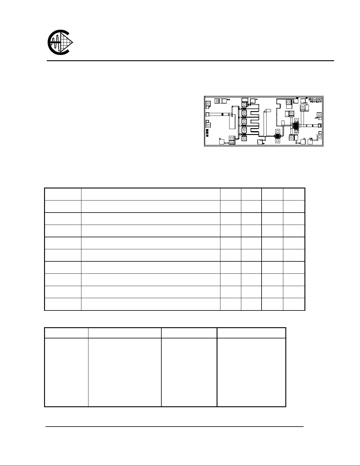
Chip Size 1060 x 2500 microns
Chip Thickness: 75 ± 13 microns
All Dimensions In Microns
F
P
1dB
Gss
∆∆Gss
NF
VSWR in
VSWR out
Idd
Vdd
Operating Frequency Range 26 32 GHz
Ouput Power at 1dB Gain Compression 20 dBm
Small Signal Gain 21 dB
Small Signal Gain Flatness
Noise Figure 6 dB
Input VSWR 2.0:1
Output VSWR 3.0:1
Power Supply Current 140 mA
Power Supply Voltage 5 8 V
± 1.5
MAXIMUM RATINGS AT 25OC
SYMBOLS PARAMETERS ABSOLUTE1 CONTINUOUS2
Vds
Vgs
Ids
Igf
Pin
Tch
Tstg
Pt
Note: 1. Exceeding any of the above ratings may result in permanent damage.
2. Exceeding any of the above ratings may reduce MTTF below design goals.
Drain-Source Voltage 12V 8V
Gate-Source Voltage -8V -3V
Drain Current Idss 215mA
Forward Gate Current 50 mA 8.5mA
Input Power 15dBm @3dB Compression
Channel Temperature 175oC 150oC
Storage Temperature -65/175oC -65/150oC
Total Power Dissipation 1 W 0.85 W
Excelics Semiconductor, Inc., 2908 Scott Blvd., Santa Clara, CA 95054
Phone: (408) 970-8664 Fax: (408) 970-8998 Web Site: www.excelics.com
dB
Page 2

TENTATIVE DATA SHEET
26 - 32 GHz Low Noise MMIC
S-PARAMETERS ( On wafer Sij measurements )
FREQ --- S11 --- --- S21 --- --- S12 --- --- S22 --(GHz) MAG ANG MAG ANG MAG ANG MAG ANG
20.00 0.33 77.79 1.28 -95.95 0.0008 44.60 0.96 85.42
20.50 0.32 68.81 1.41 -106.07 0.0011 42.01 0.96 80.89
21.00 0.30 59.18 1.57 -115.93 0.0010 52.46 0.97 75.97
21.50 0.29 48.60 1.79 -125.92 0.0014 89.17 0.97 70.79
22.00 0.27 37.50 2.09 -136.41 0.0016 91.70 0.98 65.27
22.50 0.25 25.58 2.49 -147.65 0.0006 98.47 0.99 59.31
23.00 0.24 11.90 3.02 -159.81 0.0003 98.74 1.00 52.73
23.50 0.23 -3.74 3.72 -173.45 0.0010 34.03 1.00 45.39
24.00 0.22 -20.84 4.67 171.42 0.0012 26.69 1.00 36.93
24.50 0.22 -38.46 5.89 153.98 0.0009 64.11 1.00 26.90
25.00 0.23 -56.48 7.47 134.19 0.0018 35.00 1.00 15.59
25.50 0.24 -74.69 9.29 111.36 0.0017 23.11 1.00 2.57
26.00 0.24 -92.54 11.07 86.85 0.0020 3.86 0.93 -11.48
26.50 0.25 -110.29 12.61 60.91 0.0028 -2.64 0.83 -25.69
27.00 0.25 -127.45 13.95 34.87 0.0030 -33.85 0.70 -40.01
27.50 0.26 -143.64 14.79 8.57 0.0034 -33.53 0.56 -52.60
28.00 0.25 -158.95 15.29 -17.59 0.0034 -46.81 0.43 -61.28
28.50 0.24 -173.35 15.27 -43.11 0.0019 -76.82 0.33 -63.93
29.00 0.22 171.21 15.04 -67.65 0.0023 -138.41 0.27 -60.16
29.50 0.19 155.15 14.71 -90.91 0.0029 -169.26 0.25 -54.40
30.00 0.15 138.97 14.44 -113.14 0.0042 173.19 0.26 -51.72
30.50 0.11 119.25 14.21 -135.14 0.0045 168.43 0.27 -53.13
31.00 0.05 89.26 14.12 -157.28 0.0050 138.57 0.30 -57.53
31.50 0.03 -10.38 14.03 -179.93 0.0066 110.64 0.33 -63.39
32.00 0.08 -63.92 14.02 156.67 0.0067 104.86 0.36 -71.39
32.50 0.14 -86.84 13.83 132.18 0.0074 104.16 0.40 -81.21
33.00 0.18 -103.57 13.45 106.66 0.0071 104.21 0.44 -91.19
33.50 0.21 -117.45 12.82 80.81 0.0071 116.13 0.48 -102.55
34.00 0.25 -129.30 12.12 53.53 0.0086 114.18 0.53 -114.85
34.50 0.26 -140.80 10.88 26.05 0.0100 99.52 0.55 -128.52
35.00 0.26 -149.75 9.50 -1.43 0.0112 90.23 0.55 -141.63
35.50 0.25 -153.15 8.12 -27.78 0.0099 72.51 0.54 -152.84
36.00 0.25 -156.29 6.90 -54.90 0.0141 24.34 0.50 -163.71
36.50 0.26 -151.97 5.53 -80.97 0.0137 8.68 0.46 -170.54
37.00 0.30 -149.76 4.37 -105.16 0.0128 -3.35 0.43 -175.21
37.50 0.36 -151.29 3.44 -126.85 0.0108 -11.68 0.43 -178.10
38.00 0.42 -156.26 2.71 -148.14 0.0046 -2.18 0.44 178.29
38.50 0.48 -162.95 2.14 -168.76 0.0019 54.40 0.44 173.94
39.00 0.52 -170.50 1.66 170.83 0.0036 74.41 0.44 170.08
39.50 0.56 -176.61 1.35 152.84 0.0051 78.45 0.44 166.96
40.00 0.59 178.86 1.17 138.10 0.0054 78.89 0.44 164.74
EMA406C
5V, 1/2 Idss
Page 3

TENTATIVE DATA SHEET
26 - 32 GHz Low Noise MMIC
ASSEMBLY DRAWING
V
EMA406C
dd
0.1 uF
50pF
50 ohm line on Alumina
RF OUTPUT
50 ohm line on Alumina
RF INPUT
0.1 uF
V
50pF
50pF
GG
The length of RF wires should be as short as possible. Use at least two wires between RF pad and 50 ohm line and
separate the wires to minimize the mutual inductance.
CHIP OUTLINE
1060
GND
for DC check
V
D1
1020
V
D2
1920
V
D
2050
3
RF IN
680
RF OUT
440
0
GND
370
V
0
GG1
1170
V
GG2
2080
V
GG3
for DC check
2500
Chip Size 1060 x 2500 microns
Chip Thickness: 75 ± 13 microns
PAD Dimensions: 1. DC 100 x 100 microns
2. RF 80 x 68 microns
All Dimensions In Microns
Page 4

( Vd=6V, Id=140mA)
Gain [dB]
Return loss [dB]
NF [dB]
Pout [dBm]
TENTATIVE DATA SHEET
26 - 32 GHz Low Noise MMIC
TYPICAL APPLICATION PERFORMANCE
EMA406C
Small Signal Gain
25.00
20.00
15.00
10.00
5.00
0.00
20.00 25.00 30.00 35.00 40.00
frequency [GHz]
Noise figure
20
15
10
5
0
20 25 30 35 40
(Vd 3.5V Id 80mA)
Frequency [GHz]
0
-5
-10
-15
-20
-25
-30
-35
20.00 25.00 30.00 35.00 40.00
25
23
21
19
17
15
Input & Output Return loss
(Vd=5V, Id=140mA)
S11
S22
frequency [GHz]
Linearity
(Vd=5V @28GHz)
-5 -3 -1 1 3 5
Pin [dBm]
 Loading...