

Page 1
ELM460
1234876
5
Impossible Oscillator
Description
54726
3
Features
The ELM460 is a complete astable oscillator
circuit in an 8 pin package. The circuit (impossibly!)
requires no external components to operate, as all
timing is generated internally.
Immediately after power-up, the ELM460 begins
to oscillate continuously at a frequency determined
by the logic levels on the configuration inputs. At the
end of every period, the circuit again reads these
configuration settings, and automatically adapts to
any changes that are made.
Two outputs are provided, an active high output
and it’s logical inverse. The circuit output is always a
50msec pulse, independent of the time period
selected.
Applications
• Time Base Generator
• Power Gating Controller
• LED Flasher
• Programmable Timer
• Requires no external components
• Low power CMOS design - typically 1mA at 5V
• Wide supply range - 3.0 to 5.5 volt operation
• Provides periods from 0.1 to 600 seconds
• High current drive outputs - up to 25 mA
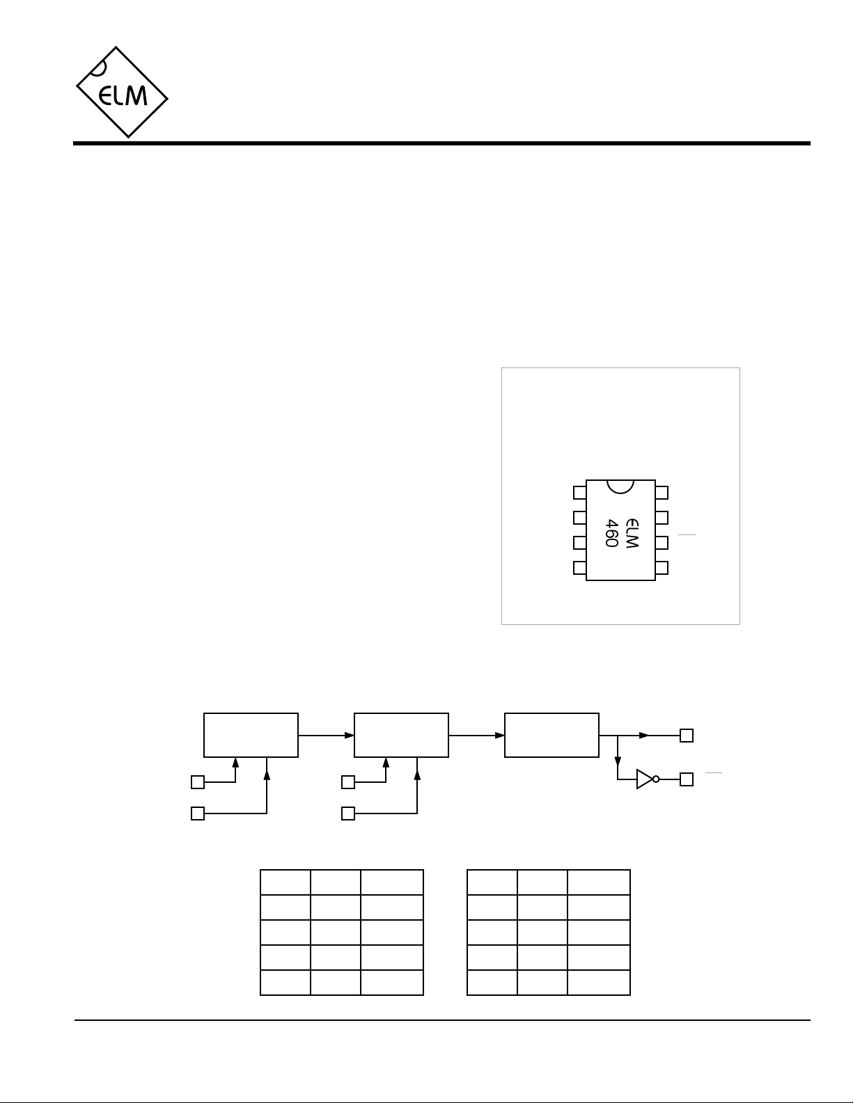
Connection Diagram
PDIP and SOIC
(top view)
VDD VSS
P1
P0
Out
Out
M0M1
Block Diagram
P1
P0
ELM460DSB
Base Period
Generator
Rate
Multiplier
M1
M0
P1 P0 Period
L
L
H
H
L
H 2 sec
L
H
1 sec
5 sec
6 sec
50ms Pulse
Generator
M1 M0
L
L
H
H
Elm Electronics – Circuits for the Hobbyist
< http://www.elmelectronics.com/ >
L
H
L
H
Out
Out
Multiplier
0.1
1
10
100
1 of 4
Page 2

ELM460
Pin Descriptions
Stresses beyond those listed here will likely damage
the device. These values are given as a design
guideline only. The ability to operate to these levels
is neither inferred nor recommended.
VDD (pin 1)
This pin is the positive supply pin, and should
always be the most positive point in the circuit.
Internal circuitry connected to this pin is used to
provide power on reset of the microprocessor, so
an external reset signal is not required. Refer to
the Electrical Characteristics section for further
information.
P1 (pin 2) and P0 (pin 3)
These two pins are used to select the base
period for oscillation. P1 is the most significant
bit, and P0 is the least. See the chart on page 1
for possible states of P1 and P0, and the
resulting periods.
M1 (pin 4) and M0 (pin 5)
These two pins determine the multiplier that
should be applied to the base period in order to
Ordering Information
determine the actual period of oscillation. Values
of 0.1, 1, 10 and 100 are possible as shown in
the chart on page 1.
Out (pin 6) and Out (pin 7)
These are the two output pins. Pin 6 is normally
held at a logical high level, and pin 7 at a logical
low. Each pin reverses its state for a period of
50ms at the beginning of each timing cycle,
independent of the overall period selected.
VSS (pin 8)
Circuit common is connected to this pin. This is
the most negative point in the circuit.
These integrated circuits are available in either the 300 mil plastic DIP format, or in the 200 mil SOIC surface
mount type of package. To order, add the appropriate suffix to the part number:
300 mil Plastic DIP............................... ELM460P 200 mil SOIC.....................................ELM460SM
Absolute Maximum Ratings
Storage Temperature.......................-65°C to +150°C
Ambient Temperature with
Power Applied....................................-40°C to +85°C
Voltage on VDD with respect to VSS............0 to +7.5V
Voltage on any other pin with
respect to VSS........................... -0.6V to (VDD + 0.6V)
All rights reserved. Copyright ©1999 Elm Electronics.
Every effort is made to verify the accuracy of information provided in this document, but no representation or warranty can be
given and no liability assumed by Elm Electronics with respect to the accuracy and/or use of any products or information
described in this document. Elm Electronics will not be responsible for any patent infringements arising from the use of these
products or information, and does not authorize or warrant the use of any Elm Electronics product in life support devices and/or
systems. Elm Electronics reserves the right to make changes to the device(s) described in this document in order to improve
reliability, function, or design.
Note:
ELM460DSB
Elm Electronics – Circuits for the Hobbyist
2 of 4
< http://www.elmelectronics.com/ >
Page 3

ELM460
Electrical Characteristics
All values are for operation at 25°C and a 5V supply, unless otherwise noted. For further information, refer to note 1 below.
Characteristic Minimum Typical Maximum ConditionsUnits
Supply Voltage, VDD 3.0 5.0 5.5 V
VDD rate of rise 0.05 V/ms
Average Supply Current, IDD 1.0 2.4 mA
Input low voltage VSS 0.15 VDD V
Input high voltage VDD V0.85 VDD
Output low voltage 0.6 V
Output high voltage VVDD - 0.7
Output Pulse Period msec50
Notes:
1. This integrated circuit is produced with a Microchip Technology Inc.’s PIC12C5XX as the core embedded
microcontroller. For further device specifications, and possibly clarification of those given, please refer to the
appropriate Microchip documentation.
2. This spec must be met in order to ensure that a correct power on reset occurs. It is quite easily achieved
using most common types of supplies, but may be violated if one uses a slowly varying supply voltage, as
may be obtained through direct connection to solar cells, or some charge pump circuits.
3. Pulse timing is affected by supply and temperature variations as shown in Figure 1 below. Results shown
are average values that can be expected.
see note 2
Current (sink) = 8.7mA
Current (source) = 5.4mA
see note 3
ELM460DSB
fast
% Error
slow
-6
-4
-2
0
+2
+4
+6
-40 0 40 80
Temperature (°C)
Figure 1. Average Timing Error
Elm Electronics – Circuits for the Hobbyist
< http://www.elmelectronics.com/ >
VDD = 5V
VDD = 3V
3 of 4
Page 4

Example Applications
ELM460
123487651234876
5
1234876
5
Uses for the ELM460 are numerous and only
limited by the imagination of the designer. Any circuit
where events are expected to occur on a regular basis
are typical applications for this device. Two example
uses are shown below.
Figure 2 shows the ELM460 used to continuously
operate a stepper motor, using an ELM311 stepper
motor controller. The ELM460 is connected to
constantly provide a step input at a rate of 10 steps per
second (P1=L, P0=L, M1=L and M0=L).
Figure 3 below shows another use for the ELM460,
directly driving an LED. The circuit is configured to
provide 1 flash every 2 seconds (P1=L, P0=H, M1=L
and M0=H). Although the IC is capable of both sinking
and sourcing relatively high currents, it’s sink
capabilities are slightly greater than it’s source (for a
given output Vds voltage drop) and that is exploited
here, by sinking the LED current. As always, a VDD
bypass capacitor is shown in the schematic, as it is
good practice to include one.
This type of flasher circuit might seem ideal at first
for burglar alarm type warning LEDs, and it would be for
many installations. Consideration should be given
however, to the fact that the ELM460 draws about 1mA
continuously from the supply. This might be too much
for some battery powered systems.
The ELM460 can be easily employed in many
circuits where timers such as the ‘555 or ‘2240 are
currently used in, without the need for timing capacitors
or charge and discharge resistors. Although the
operating voltage ranges are different, and the output
current drive of the ‘460 is not as great as the ‘555, the
ease in which it is connected, and its ability to be
programmed with logic level signals, are appealing to
the designer. All of these types complement one
another, however, and each should be chosen on its
merits for the particular application.
A
+5V
To winding
drive circuits
0.1µF
B
0.1µF
C
D
Figure 2. Continuously Running a Stepper Motor
+5V
300Ω
+5V
Figure 3. LED Flasher
ELM460DSB Elm Electronics – Circuits for the Hobbyist
< http://www.elmelectronics.com/ >
4 of 4
 Loading...