

Page 1
1
• Class 2 (active energy)
• Class 3 (reactive energy)
• Active reactive energy meter
• Direct connection up to 90A
• Electromechanical display 6+1DGT
• LED for the indication of the consumed energy
• Selection of the displayed energy by means of dip-switch
• Optional pulse output (as a module)
• Self power supply or auxiliary power supply
115VAC, 230VAC 50-60Hz
• Full compliance with EN61036 (active energy, class 2)
•
Full compliance with EN61268 (reactive energy, class 3)
• Dimensions: 9 DIN-modules
• Sealable housing
Product description
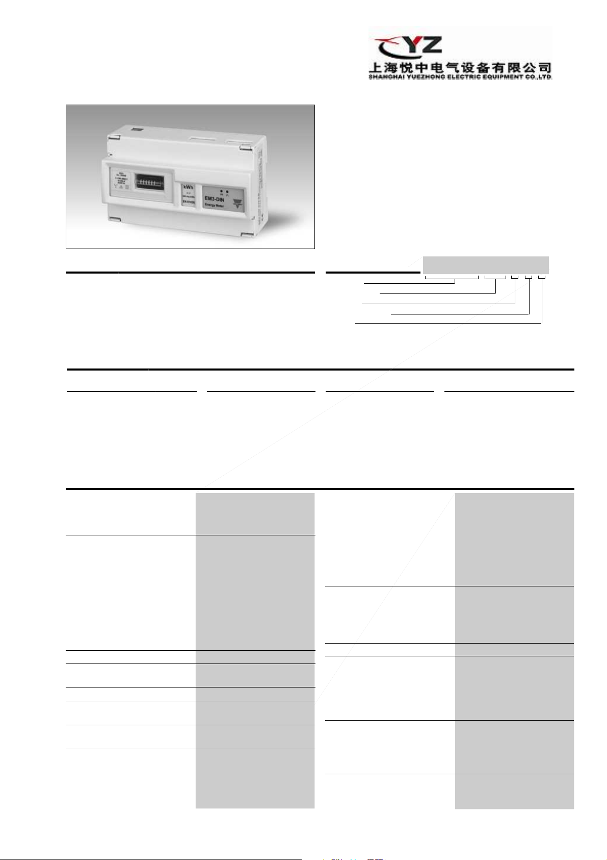
EM3-DIN is a three-phase
energy meter for the measure
of active or reactive energy;
the 208V
L-L
, 220V
L-L
and
400V
L-L
meters are self-sup-
plied, while the 660V
L-L
meters
are provided with auxiliary
power supply. EM3-DIN is
provided with: 6+1DGT electromechanical indicator for
the indication of kWh or
kvarh; one green LED for the
indication of power ON; one
red LED blinking proportionally to the consumed energy
.
Energy Management
Energy Meter with Output Module
Type EM3-DIN
Type selection
Range code
Auxiliary Power Supply (C or D):
AV3: 660V
L-L
/ 20(90)AAC
Self Power Supply (X):
AV2: 220V
L-L
/ 20(90)AAC
AV8: 208V
L-L
/ 20(90)AAC
AV9: 400V
L-L
/ 20(90)AAC
Model
Range code
System
Power supply
Slot A
How to order
EM3-DIN AV9 3 X X
Accuracy
Active energy
Class 2, according to EN61036
Reactive energy
Class 3, according to EN61268
Start-up current 80mA
Additional errors
Acc. to EN61036, EN61268
Voltage variation
< 0.5%
Frequency variation < 0.5%
Wave form <1% (3
rd
harmonic: 10%)
Voltage disymmetry < 0.5% (referred to the
rated input voltage)
External continuous magnetic
induction 0
Magnetic induction 0 (up to 0.5 mT)
HF electromagnetic field < 1%
Accessories influence 0
Temperature drift
≤ 250 ppm/°C
Measurements Active or reactive energy
Wave form sinusoidal and distorted
Crest factor (I ≤ 20A) ≤ 6 (127A peak max)
Basic current (Ib) 20A (according to EN61036
/EN61268)
Maximum current (Imax) 90A (according to EN61036/
EN61268)
Overload
Continuous: current 4.5 x Ib
For 10ms: current 30 Imax @ 50Hz
Rated input voltage
AV2 (AE2004) Un: 220V
L-L
,
-10%≤Un≤+15%, 50-60Hz
AV3 (AE2002, AE2003) Un: 660V
L-L
,
-20%≤Un≤+15%, 50-60Hz
AV8 (AE2001) Un: 208V
L-L
,
-20%≤Un≤+15%, 50-60Hz
AV9 (AE2000) Un: 400V
L-L
-20%≤Un≤+15%, 50-60Hz
Input impedance
AV2 > 720kW (220V
L-L
), ≤ 4VA
AV3 > 1.97MW (660V
L-L
), ≤ 4VA
AV8 > 720KW (208V
L-L
), ≤ 4VA
AV9 > 720KW (400V
L-L
), ≤ 4VA
Frequency 50-60 Hz
Electrical system 3-phase, balanced or
unbalanced with or without
neutral. Note: in the selfsupplied version, the neutral
must be connected to the
measuring inputs.
Display Electromechanical type
6+1 DGT
Power supply Green LED, ON if supplied
Energy consumption Red LED, 640 imp./kWh/
kvarh (min. period: 0.5s)
Selection of displayed energy By means of DIP-switch
Dip-switch 1 ON: active energy
OFF: reactive energy
Input specifications
System
3 : Three-phase,
unbalanced load
Power supply
C: 115VAC - 15+10%
50-60Hz (only range AV3)
D: 230VAC -15+10%
50-60Hz (only range AV3)
X: Self power-supply
Slot A (retransmission)
X:
None
O: Module AO2900
Dual open collector
pulse output
R: Module AO2910
One relay output + one
open collector output.
Important note: the AV2 model is suitable only for three-phase
unbalanced system without neutral.
Page 2
2
Available models and modules
Pulse outputs (on request) AO2900, slot A
Number of outputs 2
Pulse outputs to be used as
retransmission of the
energies:
Channel 1 active energy
Channel 2 reactive energy
Number of pulses 10 / kWh, 10 / kvarh
Type
Open collector (NPN transistor)
VON1.2VDC / max 100mA
V
OFF
30VDC max
Pulse duration 220ms (ON), ≥200ms (OFF)
according to DIN43864
Leakage current ≤10µA, @ 30V, 60°C
Insulation By means of optocouplers,
2000Vrms for 1 minute
between measuring inputs
and pulse outputs.
Insulation between the two
outputs: functional
AO2910 module Relay + open collector
output. Working mode like
AO2900.
Pulse output One static output+one relay
output, other characteristics
like AO2900.
Output type Static type like module
AO2900; Relay type: SPDT,
AC1, AC15: 1AAC @250VAC
Insulation 2000 V
RMS
outputs to
measuring inputs,
2000 V
RMS
output to
supply input.
Insulation between the two
outputs: 2000 V
RMS
EM3-DIN
Output specifications
Self power supply 400VAC
V
L-L
-20% +15% 50-60Hz
208VAC
V
L-L
-20% +15% 50-60Hz
220VAC
V
L-L
-10+15%, 50-60Hz
Auxiliary power supply 230VAC -15+10% 50-60Hz
115VAC -15+10% 50-60Hz
Power supply specifications
Standards
Metrology EN61036, EN61268
Safety IEC-664
Pulse output DIN 43864
Connections Screw-type,
Cable cross-section area
Max. 35 mm2 (measuring inputs)
Min. 6 mm2 (measuring inputs)
Other inputs: 4 mm
2
Min./Max. screws tightening torque 2 Nm / 6 Nm (90A inputs)
Housing
Dimensions 162.5 x 90 x 63 mm
Material ABS, NORYL,
PC self-extinguishing
Mounting DIN-rail or wall
Degree of protection Front: IP40
Screw terminals: IP20
Weight Approx. 800 g
(packing included)
Operating temperature
-20 to +55°C (14°F to 131°F)
(R.H. from 0 to 90%
non-condensing @ 40°C)
according to EN61036
and EN61268
Storage temperature
-20 to +70°C (14°F to 140°F)
Dielectric strength 4000Vrms for 1 minute
Installation category Cat. lll (IEC 664)
EMC
Burst 4kV / level 4 (EN61000-4-4)
Immunity to irradiated
electromagnetic fields
10V/m from 26 to 1000MHz
(EN61000-4-3)
Electrostatic discharges 15kV (EN61000-4-2)
Radio frequency emissions according to CISPR 14
and CISPR 22
Pulse voltage (1.2/50µs) 8kV (EN61000-4-5)
General specifications
Type Inputs Power Number of Ordering
Supply channels code
EM3-DIN AV9.3.X
400V
L-L
/ 20(90)AAC
Self power supply AE2000
EM3-DIN AV8.3.X
208V
L-L
/ 20(90)AAC
Self power supply AE2001
EM3-DIN AV2.3.X
220V
L-L
/ 20(90)AAC
Self power supply AE2004
EM3-DIN AV3.3.C
660V
L-L
/ 20(90)AAC 115VAC - 15+10%
AE2002
EM3-DIN AV3.3.D
660V
L-L
/ 20(90)AAC 230VAC - 15+10%
AE2003
Open collector output 2 AO2900
Relay + open coll. output 2 AO2910
Page 3
3
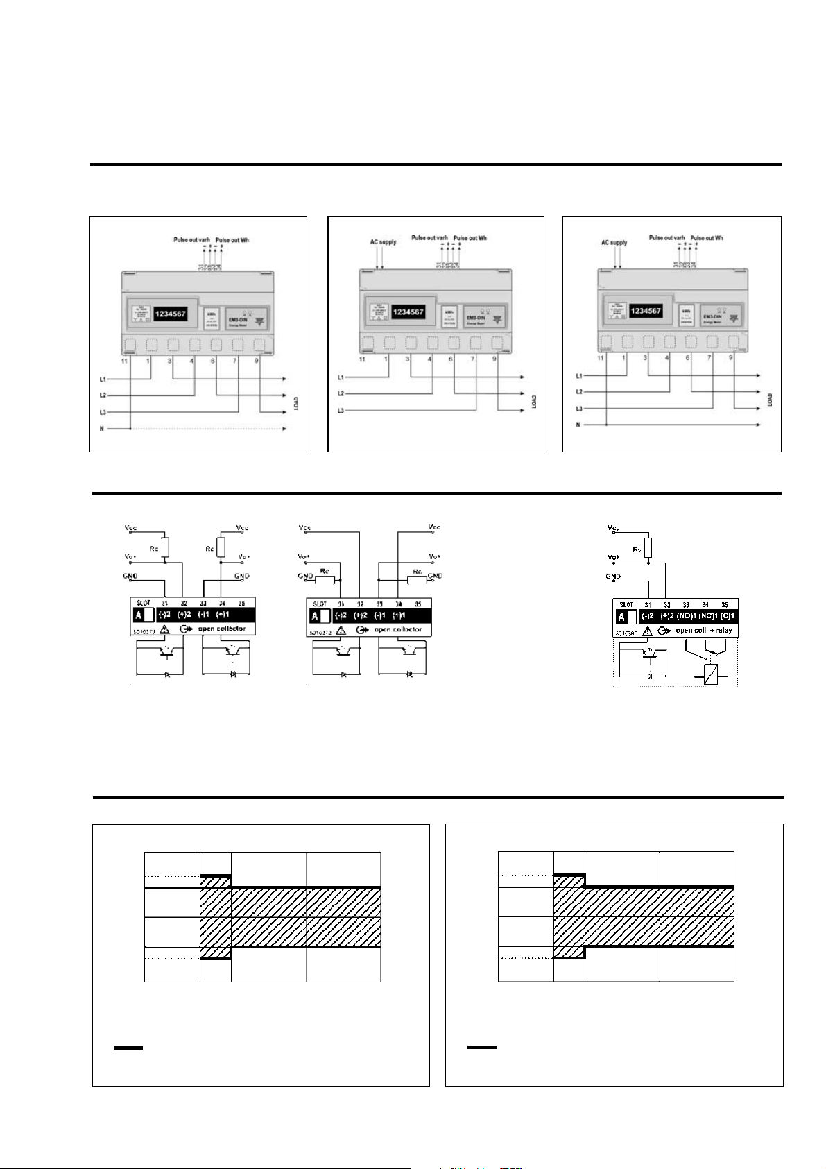
Wiring diagrams
EM3-DIN 20(90)A
Direct connection (3-phase system + N) Direct connection (3-phase system)
Direct connection (3-phase system + N)
EM3-DIN
Self power-supplied Fig. 1
Wiring diagrams (optional module)
Only open collector outputs: the grounds of the outputs are separated, and therefore it’s possible to carry out, for the same module,
two different connections. The load resistance (Rc) must be designed so that the closed contact current is lower than 100mA; the
VDC voltage must be lower than or equal to 30V.
Open collector output Fig. 1
Auxiliary power-supply Fig. 2
Auxiliary power-supply Fig. 3
Accuracy
Accuracy (RDG) depending on the current
Error
90A (Imax)
20A (Ib)
2A
(0.1) Ib
1A
(0.05 Ib)
+2%
+4%
-4%
0%
+2.5%
-2%
EN 61036/ IEC 61036 limits
Active energy
Start-up current: 80mA
-2.5%
Accuracy (RDG) depending on the current
Error
90A (Imax)
20A (Ib)
2A
(0.1) Ib
1A
(0.05 Ib)
+3%
+5%
-5%
0%
+4%
-3%
EN 61268/ IEC 61268 limits
Reactive energy
Start-up current: 80mA
-4%
Relay + open collecttor output Fig. 2
Page 4
4
EM3-DIN
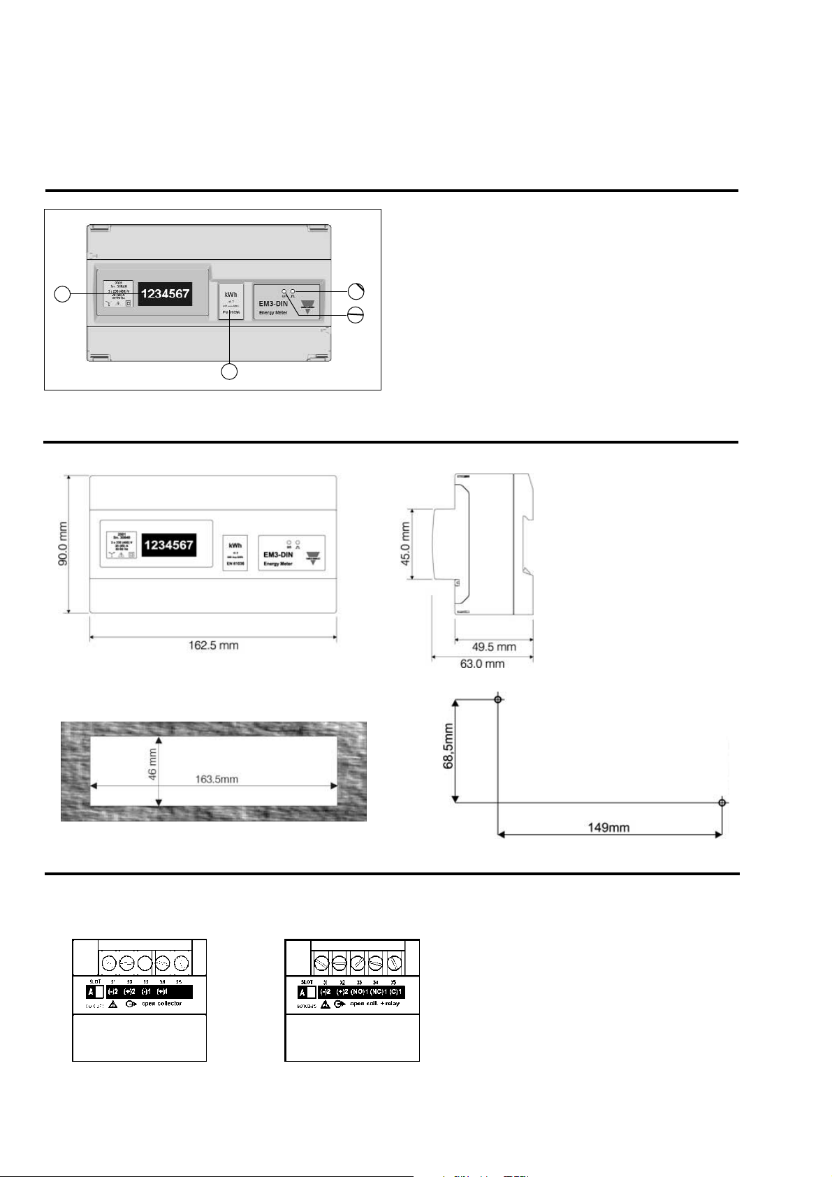
Dimensions
1. Red LED
Indicates the consumed energy (640 pulses / kWh,
minimum period 0.5ms) blinking proportionally.
2. Green LED
Indicates power ON.
3. Display
Electromechanical type, 6+1 DGT, displays kWh or kvarh
according to the selection made by means of an internal
dip-switch.
4. Engineering unit
Removable double sided [front (kWh) / back (kvarh)] label
Front panel description
1
3
2
4
Terminal board
Dual open collector
output module
AO 2900
Realy + open collecttor output
AO 2910
 Loading...