

Page 1
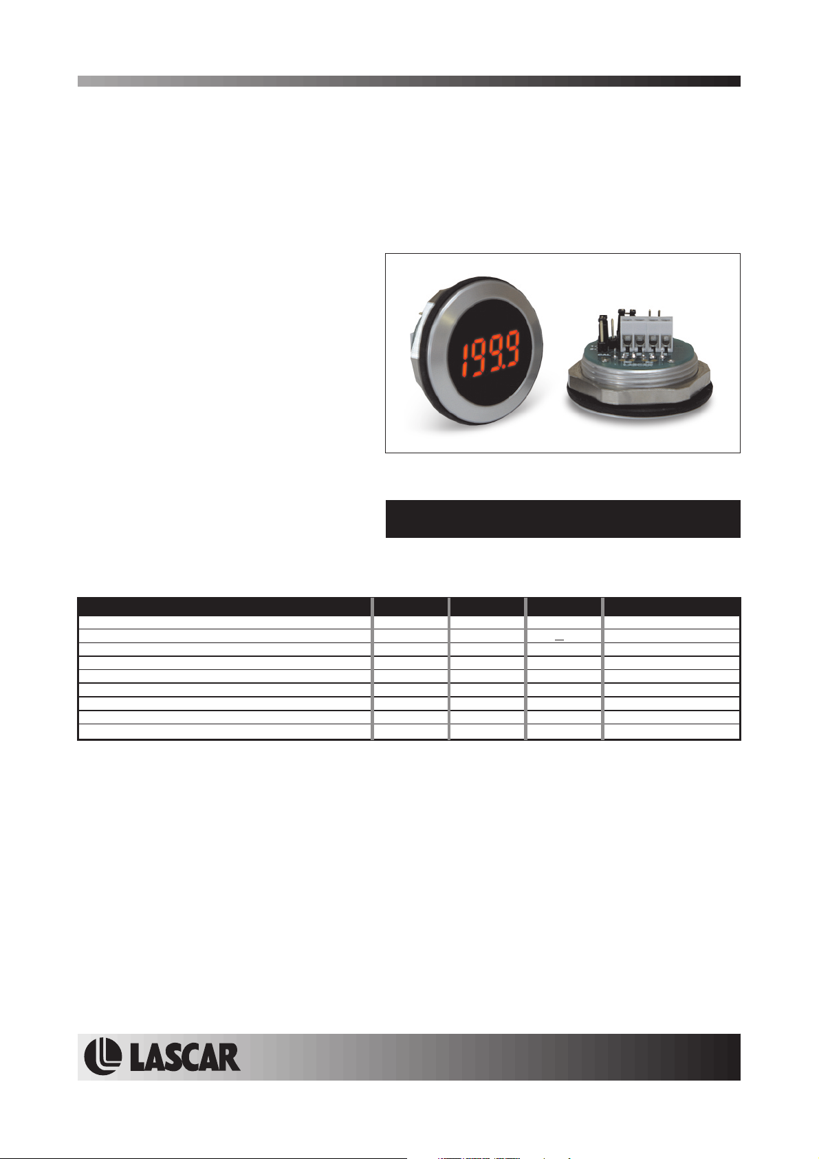
EM32-1B-LED
Round Hole Mounting LED Voltmeter
PRODUCT DESCRIPTION
The EM32-1B-LED isa3½digitLEDvoltmeterwhichis designed to be panel mounted in most low and medium
volume applications. The meter features 8mmdigitheight,3decimalpoints,auto-polarity,auto-zero, 200mVfull
scale reading and a lowcurrent consumption.This product is designed sono soldering is required. Connection is
via screw terminals, and options are selected via jumper links. The module features a round metal bezel,
requiring a 32.5mm(1.28") diametercut-out. Itis secured withthe nut provided. Protection fromthe front to IP67
/ NEMA 4Xstandards is achievedby placing the rubber seal betweenthe module andpanel during assembly.
FEATURES
•8
mm (0.31") Digit Height
• 200mV d.c. Full Scale Reading
• 50mA @ 5Vd.c. Operation
•
Auto-zero and Auto-polarity
• Selectable
• Requires 32.5mm (1.28") Diameter Cut-out
• IP67 / NEMA 4X Protected
Decimal Points
TYPICAL APPLICATIONS
• Panel Mount Instrumentation
• Process & Control
• Automotive
ORDERING INFORMATION
Stock Number
Standard Meter EM32-1B-LED
ELECTRICAL SPECIFICATIONS
Specification Min. Typ. Max. Unit
Accuracy (overall error) * 0.1 % (±1 count)
Linearity 1 count
Sample rate 2.5 samples/sec
Operating temperature range 0 50 °C
Temperature stability 150 ppm/°C
Warm-up time 10 minutes
Supply voltage (V+ to V-) 4.75
Supply current 50 100 mA
Input leakage current (Vin = 0V) 1 10 pA
* To ensure maximum accuracy, re-calibrate periodically.
** Operation of the meter beyond the maximum supply voltage rating may cause permanent damage to the meter.
Unless otherwise noted,specifications apply atT =25°C, V =5Vd.c. and aretested with themodule configured for floatinginput mode.
A supply
5 5.25 V d.c.
+
SAFETY
To comply with the Low Voltage Directive (LVD 93/68/EEC), input voltages to the module’s pins must not exceed
60Vdc. The user must ensurethat the incorporation of the panelmeter into the user’s equipment conforms to the
relevant sections of BS EN 61010 (Safety Requirements for Electrical Equipment for Measuring, Control and
Laboratory Use).
LASCAR ELECTRONICS LTD.
MODULE HOUSE
WHITEPARISH
WILTSHIRE SP5 2SJ
UK
TEL: +44 (1794) 884567
FAX: +44 (1794) 884616
E-mail: [email protected]
LASCAR ELECTRONICS INC.
3750 West 26th Street
Erie
PA 16506
USA
TEL: +1 (814) 835 0621
FAX: +1 (814) 838 8141
E-mail: [email protected]
www.lascarelectronics.com
LASCAR ELECTRONICS (HK) LIMITED
FLAT C, 5/FL., LUCKY FTY. BLDG.
63-65 HUNG TO ROAD
KWUN TONG KOWLOON
HONG KONG
TEL: +852 2797 3219
FAX: +852 2343 6187
E-mail: [email protected]
Page2of4Page 2 of 4
Page1of4
Page 2
EM32-1B-LED
Round Hole Mounting LED Voltmeter
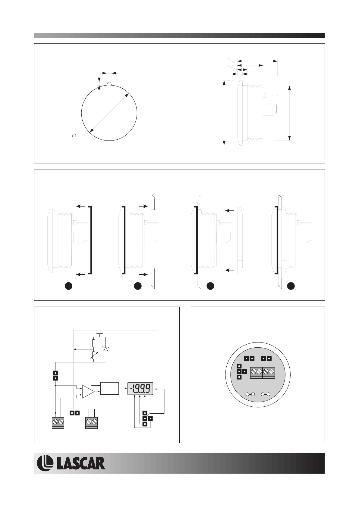
DIMENSIONS
All dimensions in mm (inches)
1.7 (0.07)
32.5
(1.28)
Panel cut-out
PANEL MOUNTING
1.5 (0.06)
15.0 (0.59)
5.5 (0.22)
3.0 (0.12)
38.0 (1.5)
23.5 (0.93)
32.0 (1.26)
23 41
FUNCTIONAL BLOCK DIAGRAM
V+
RHI
COM
J2
RLO
ILO
IHI
+
_
V+ V-
J1
ILO IHI V+ V-
CAL
A/D
Vref
8
1
DP 3 2 1
www.lascarelectronics.com
CONNECTIONS (rear view)
J2J1
0V
V+
IHI
ILO
RB
RA
Page2of4Page 2 of 4
Page2of4
Page 3
EM32-1B-LED
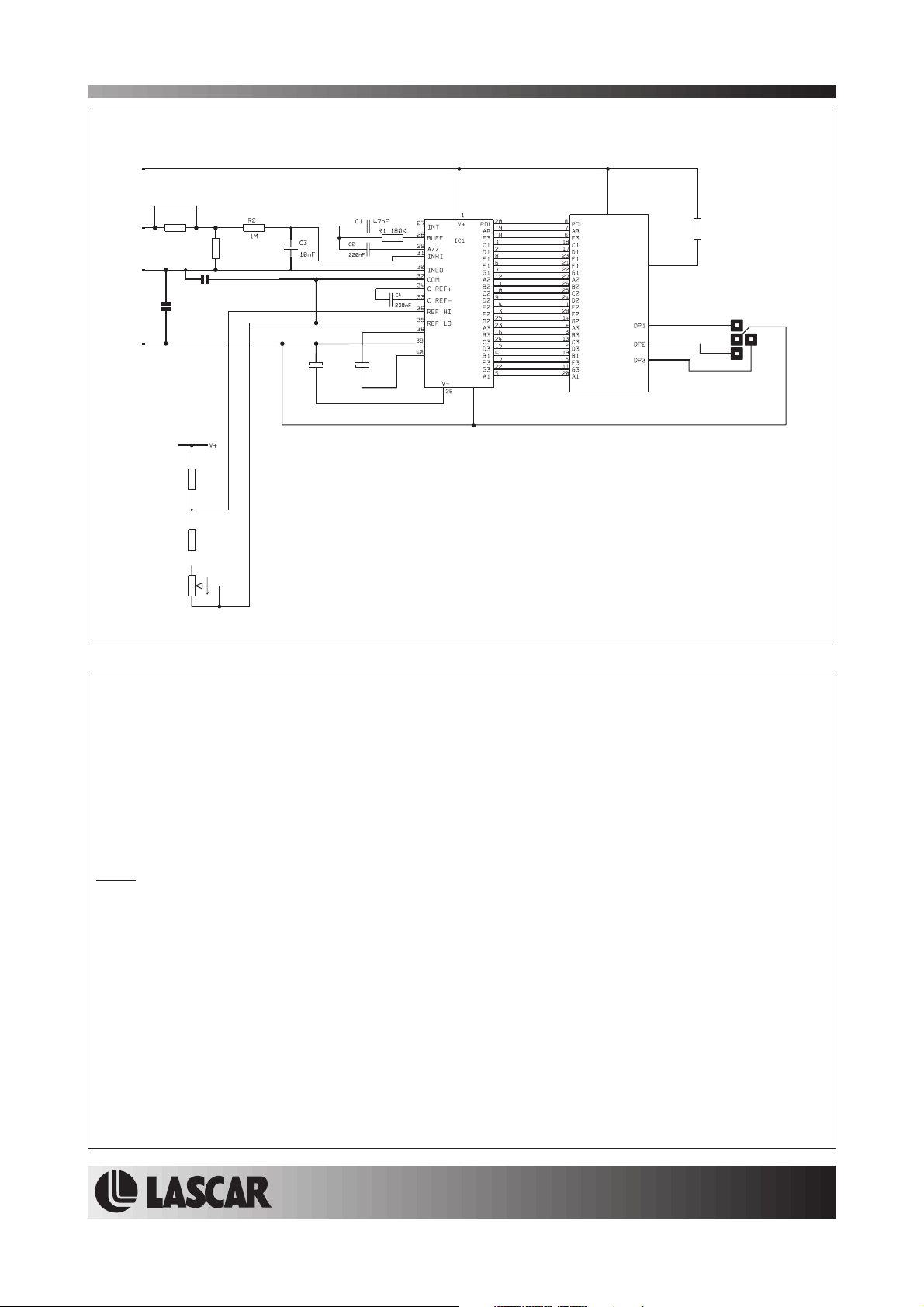
CIRCUIT DIAGRAM
V+
Round Hole Mounting LED Voltmeter
IHI
ILO
0V
Ra
J2
R4
100k
R5
3k0
R6
1k0
R7
Rb
J1
C6
C6
1u5
1u5
CAP-
GND
CAP+
MAX140
DGND
21
ANODE
DP1, DP2, DP3
DISPLAY
1k5
SCREW TERMINAL FUNCTIONS
0V Negative power supply to themeter.
V+ Positive power supply to the meter (+5Vnom).
IHI Positivemeasuring input.
IHI must be no closerthan1.5V to eitherthepositive or theinternal negative supply.
ILO Negative measuring input.
ILO must be no closerthan1.5V to eitherthepositive or theinternal negative supply.
Note:
Internal negative supply. This is generated from the supply voltage between V+ and 0V, and is negative
with respect to 0V.
For example: if V+ = +5V (with respect to 0V), then the allowable common mode input range is from
(V+ - 1.5V) to (V- + 1.5V)orfrom 3.5V to -3.5V with respecttothe 0V powersupplyconnection.
JUMPER LINKS
J1 ConnectsILO to COM, when jumperlinkis fitted.
J2 Connects ILOto 0V, when jumper link isfitted.
www.lascarelectronics.com
Page2of4Page 2 of 4
Page3of4
Page 4
EM32-1B-LED
Round Hole Mounting LED Voltmeter
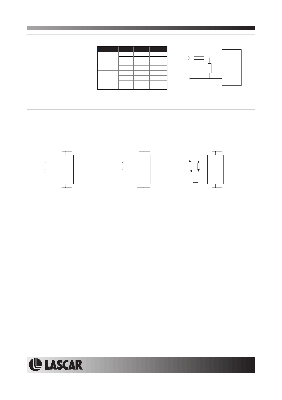
SCALING
Two resistors Ra and Rb
may be used to alter the
full scale reading (FSR) of
the meter - see table. The
meter will have to be recalibrated by adjusting the
calibration potentiometer
on the rearof the module.
Voltage
Vin 200V 1M 1k
Current
Iin 20mA 0R 10R
*Ensure that Ra is rated for high voltage use.
FSR Ra Rb
2V 910k 100k
20V 1M 10k
2000V* 1M 100R
200 A 0R 1k
µ
2mA 0R 100R
200mA 0R 1R
+
Vin or inI
-
Ra
Rb
IHI
EM32-1B-LED
ILO
APPLICATIONS
Do not connect more than one meter to the same power supply if the meters cannot use the same signal
ground. Taking any inputbeyond the power supplyrails will damage themeter.
+4.75 to +5.25V +4.75 to +5.25V
+
±200mV
-
Measuring an input voltage referenced
to a floating supply, i.e. the input
voltage and the meter's power supply
are isolated from each other.
Ensure Jumper link J1 is fitted.
Ensure Jumper link J2 is not fitted.
V+
IHI
ILO
0V
0V
+
±200mV
-
Measuring a single ended input
voltage referenced to supply, i.e. the
input voltage and the meter's power
supply share the same 0V rail.
Ensure Jumper link J1 is not fitted.
Ensure Jumper link J2 is fitted.
V+
IHI
ILO
0V
0V
+4.75 to +5.25V
V+
IHI
R
ILO
R = 0.2
I
FSR
Measuring current.
The meter's supply is isolated
from the current being measured.
Ensure Jumper link J1 is fitted.
Ensure Jumper link J2 is not fitted.
0V
0V
Specifications liable to change without prior warning EM32-1B-LED Issue 1 February/2003 M.C. Applies to EM32-1B-LED/1
Page4of4Page 4 of 4
www.lascarelectronics.com
Page4of4
 Loading...