

Page 1
ELM365
1234876
5
Security System Controller
235
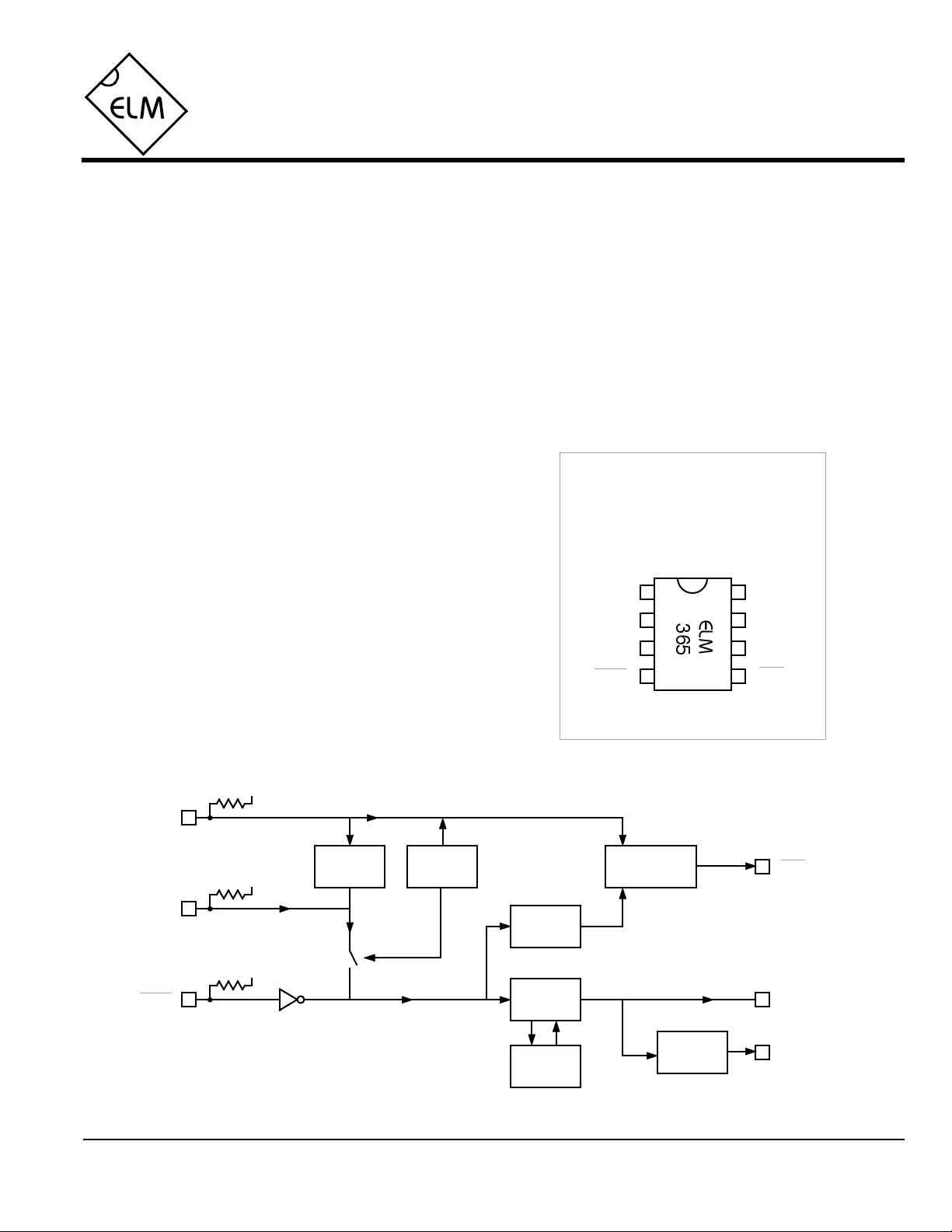
Description
467
Features
The ELM365 provides all of the logic necessary
for a complete security system in an 8 pin package.
The circuit is capable of monitoring two normally
closed input loops and one normally open panic
circuit, provides a constant level and a pulsing alarm
output, and the logic to drive a status LED.
Internal timers are provided for alarm blocking
during zone entry and exit as well as circuit
resetting, should alarms go unacknowledged.
Debouncing of all of the inputs is also provided
internally, to allow for the direct interfacing to
mechanical switches.
Due to the digital techniques employed, no
external support components are required for any of
the timing functions, resulting in considerable cost
savings over other designs.
Applications
• Home or cottage security systems
• Auto or RV security systems
• Individual zone monitoring in a multizone system
• High or low limit warning alarms
• Low power CMOS design - typically 1mA at 5V
• Wide supply range - 3.0 to 5.5 volt operation
• Simultaneous monitoring of three circuits
• 45 second delay for entry and exit
• Automatic reset of alarm outputs after 5 minutes
• Status LED output driver
• High current drive outputs - up to 25 mA
• Panic input for instant triggering of the alarm
Connection Diagram
PDIP and SOIC
(top view)
VDD VSS
DLoopOutP
OutC
panic
ILoop
LED
Block Diagram
DLoop
ILoop
panic
ELM365DSB
VDD
VDD
VDD
45 sec
Delay
45 sec
PowerUp
Alarm
Latch
Alarm
Latch
5 min
Reset
fast
slow
Elm Electronics – Circuits for the Hobbyist
< http://www.elmelectronics.com/ >
LED
Flasher
1.5s on
0.5s off
LED
OutC
OutP
1 of 4
Page 2

ELM365
Pin Descriptions
VDD (pin 1)
This pin is the positive supply pin, and should
always be the most positive point in the circuit.
Internal circuitry connected to this pin is used to
provide power on reset of the microprocessor, so
an external reset signal is not required. Refer to
the Electrical Characteristics section for further
information.
OutP (pin 2)
This is the (active high) pulsed alarm output.
When in an alarm state, it alternates between a
logic high level (VDD) for 1.5 seconds and a low
level (VSS) for 0.5 seconds. This output
automatically resets after 5 minutes.
OutC (pin 3)
This is the constant level alarm output. It is
switched to a high level (VDD) during an alarm
condition, and is otherwise at a logic low level.
This output automatically resets to a low level
after 5 minutes.
panic (pin 4)
This active low input is debounced and used to
immediately trigger an alarm from normally open
inputs such as panic pushbuttons or tamper
switches. If unused, this input can be left open
circuited, as there is an internal pullup resistor on
the pin (see the specs).
LED (pin 5)
This is an active low LED drive output. It will
pulse rapidly to warn that the system is in a 45
second delayed alarm period, or will pulse slowly
(about 1.5 seconds on, 0.5 seconds off) if an
alarm is in progress or has previously occurred.
By adding a suitable series resistor, an LED can
be directly driven from this pin.
ILoop (pin 6)
This pin is used for monitoring a normally closed
loop, connected between the pin and VSS. To
reduce the possibility of nuisance triggers, a 0.5
second debounce period is provided on this input.
An alarm will be initiated immediately after the
loop is determined to be open, but will not
retrigger an alarm if the loop remains open, after
the five minute timeout. This pin is not enabled for
the first 45 seconds after the system is first turned
on.
DLoop (pin 7)
This pin is similar to pin 6, with the one exception
being that the alarm is delayed by 45 seconds to
allow time for entry or exit.
VSS (pin 8)
Circuit common is connected to this pin. This is
the most negative point in the circuit.
Ordering Information
All rights reserved. Copyright ©1999 Elm Electronics.
Every effort is made to verify the accuracy of information provided in this document, but no representation or warranty can be
given and no liability assumed by Elm Electronics with respect to the accuracy and/or use of any products or information
described in this document. Elm Electronics will not be responsible for any patent infringements arising from the use of these
products or information, and does not authorize or warrant the use of any Elm Electronics product in life support devices and/or
systems. Elm Electronics reserves the right to make changes to the device(s) described in this document in order to improve
reliability, function, or design.
ELM365DSB
These integrated circuits are available in either the 300 mil plastic DIP format, or in the 200 mil SOIC surface
mount type of package. To order, add the appropriate suffix to the part number:
300 mil Plastic DIP............................... ELM365P 200 mil SOIC.....................................ELM365SM
Elm Electronics – Circuits for the Hobbyist
< http://www.elmelectronics.com/ >
2 of 4
Page 3

ELM365
Absolute Maximum Ratings
Stresses beyond those listed here will likely damage
the device. These values are given as a design
guideline only. The ability to operate to these levels
is neither inferred nor recommended.
Storage Temperature.......................-65°C to +150°C
Note:
Ambient Temperature with
Power Applied....................................-40°C to +85°C
Voltage on VDD with respect to VSS............0 to +7.5V
Voltage on any other pin with
respect to VSS........................... -0.6V to (VDD + 0.6V)
Electrical Characteristics
All values are for operation at 25°C and a 5V supply, unless otherwise noted. For further information, refer to note 1 below.
Characteristic Minimum Typical Maximum ConditionsUnits
Supply Voltage, VDD 3.0 5.0 5.5 V
VDD rate of rise 0.05 V/ms
Average Supply Current, IDD 1.0 2.4 mA
Internal pullup resistances 300 500 600 KΩ Panic input, see note 4
20 30 50 KΩ Loop inputs, see note 4
Output Pulse Duration- High 1.5 sec OutP and LED outputs,
0.5 sec- Low
see note 2
VDD = 5V, see note 3
see note 5
Auto Reset Time Period 5 min see note 6
Input low voltage - reset pin VSS 0.15 VDD V
Input high voltage - reset pin VDD V0.85 VDD
Output low voltage 0.6 V
Output high voltage VVDD - 0.7
Current (sink) = 8.7mA
Current (source) = 5.4mA
Notes:
1. This integrated circuit is produced with a Microchip Technology Inc.’s PIC12C5XX as the core embedded
microcontroller. For further device specifications, and possibly clarification of those given, please refer to the
appropriate Microchip documentation.
2. This spec must be met in order to ensure that a correct power on reset occurs. It is quite easily achieved
using most common types of supplies, but may be violated if one uses a slowly varying supply voltage, as
may be obtained through direct connection to solar cells, or some charge pump circuits.
3. Pullup resistor currents are not included in this figure.
4. The value of the internal pullup resistance is both supply and temperature dependent.
5. Times are approximate. LED output can only be reset by powering down.
6. Both the OutP and OutC outputs will be internally reset after this time. If a loop continues to remain open, it
will not retrigger an alarm. In contrast, the panic input will always retrigger an alarm if it remains closed.
ELM365DSB
Elm Electronics – Circuits for the Hobbyist
3 of 4
< http://www.elmelectronics.com/ >
Page 4

Example Application
ELM365
Figure 1 shows the ELM365 as the controller in a
typical home security system.
Series connected magnetic switches monitor door
positions, and connect to the delayed loop input. Several
window switches are connected in series to the instant
loop input, and panic switches are provided in the
bedrooms to cause an alarm when pressed.
Four LEDs are included in the circuit to show power
on (circuit armed), alarm, and loop status. In addition to
status, these LEDs also provide loop current for switch
wetting, and assist with the input pullup function.
Although not essential, it is recommended that the LEDs
be installed.
+5V
Panic
Switches
2.2KΩ
+5V
+5V
Alarm
Instant
Loop
300Ω
1.0KΩ
+5V
300Ω
5
6
7
8
2.2KΩ
The series resistors on pins 4, 6, and 7 have been
included in this design for protection from electrostatic
discharge, or induced currents. Although the circuit will
function correctly without them, they are recommended
for the added protection that they afford.
The circuit supports two outputs, and both have
been included with this design. The pulsed output
drives an alarm buzzer, while the constant output can
drive yard lights, etc. Both outputs use a conventional
transistor circuit to energize a 12V relay coil.
Power for the circuit is from an AC supplied 12V
DC source, with only temporary backup provided by a
9V battery. Both inputs are diode coupled, passed
through the key switch, and reduced by the 78L05
regulator to 5V for the logic.
+12V
1N4001
Constant
2.2KΩ
4
Output
2N3904
3
2
+12V
1
ELM365DSB Elm Electronics – Circuits for the Hobbyist
Delayed
Loop
Normal
12V Supply
Optional 9V
Backup Supply
300Ω
1.0KΩ
Key Switch
(Arm/Disarm)
Power
300Ω
78L05
0.1µF
+5V
0.1µF
< http://www.elmelectronics.com/ >
1N4001
Pulsed
2.2KΩ
Output
2N3904
Figure 1. Home Security System
4 of 4
 Loading...