

Page 1

ST/SV 3210 & ST/SV 3306
Operator’s Manual
Page 2

Page 3

CG Triumvirate is a trademark of Agfa Corporation.
Copyright Information:
Firmware (Software) Agreement
The enclosed Firmware (Software) resident in the EPROM’s is owned by Licensor or its
suppliers and is licensed for used only on a single printer in the user’s Trade or Business.
The User agrees not to, and not to authorize or permit any other person or party to,
duplicate or copy the EPROM’s or the information contained in the EPROM’s. The
firmware (Software) is protected by applicable copyright laws and Licensor retains all
rights not expressly granted. In no event will Licensor or its suppliers be liable for any
damages or loss, including direct, incidental, economic, special, or consequential
damages, arising out of the use or inability to use the Firmware (Software).
Information in this document is subject to change without notice and does not represent a
commitment on the part of Datamax Barcode Products Corporation. No part of this
manual may be reproduced or transmitted in any form or by any means, for any purpose
other than the purchaser's personal use, without the expressed written permission of
Datamax Corporation.
All rights reserved. Printed in the United States of America.
© Copyright 2002 by Datamax Corporation
Part Number: 88-2240-01
Revision: E
Page 4
Page 5

Agency Compliance and Approvals:
UL1950 Information Technology Equipment
C22.2 No. 950-M93
C US
Listed
EN60950
For 230 Volt Operation (Europe): Use a cord set, marked "HAR," consisting
of a min H05VV-F cord which has a minimum 0.75 square mm diameter
conductors, provided with an IEC 320 receptacle and a male plug for the
country of installation rated 6A, 250V
Für 230 Volt (Europa): Benützen Sie ein Kabel, das mit "HAR" markiert ist,
bestehend mindestens aus einem H05VV-F Kabel, das mindestens 0,75
Quadratmillimeter Drahtdurchmesser hat; sowie eine IEC320 Steckdose und
einen für das Land geeigneten Stecker, 6A, 250 Volt.
As an Energy Star Partner, the manufacturer has determined that this product
meets the Energy Star guidelines for energy efficiency.
The manufacturer declares under sole responsibility that this product conforms
to the following standards or other normative documents:
EMC: EN55022 (1993) Class B
EN50082-1 (1992)
EN61000-3-2 (1995)
EN61000-3-3 (1995)
IEC 801-2 (1991), 8kV CD; 15kV AD
IEC 801-3 (1984), 3 V/m
IEC 801-4 (1988), 500V Signal Lines
EN 55024 (1998) SV Model Only
Safety: This product complies with the requirements of EN 60950/A11:1997
1kV AC Power Lines
Gost-R
FCC: This device complies with FCC CFR 47 Part 15 Class A.
þ Note: This equipment has been tested and found to comply with the limits for a Class A
digital device, pursuant to Part 15 of the FCC Rules. These limits are designed to
provide reasonable protection against harmful interference when the equipment is
operated in a commercial environment. This equipment generates, uses, and can
radiate radio frequency energy, and if not installed and used in accordance with
the instructions in this manual, it may cause harmful interference to radio
communications. Operation of this equipment in a residential area is likely to
cause harmful interference in which case the user will be required to correct the
interference at his own expense.
Page 6

Important Safety Instructions:
This printer has been carefully designed to give many years of safe and
reliable performance; however, as with all types of electronic equipment,
there are some basic precautions that should taken to avoid personal
injury or damage to the printer:
Ø Carefully read the installation and operating instructions provided
with this printer.
Ø Read and follow all warning instruction labels on the printer.
Ø Place ST Model printers on a flat, firm surface; mount SV Model
printers in a flat, rigid enclosure.
Ø To protect the printer from overheating, make sure no openings on
the printer are blocked.
Ø Do not place the printer on or near a heat source.
Ø Do not use the printer near water and never spill liquid into it.
Ø Ensure that the power source meets the ratings listed on the printer;
if uncertain, check with your dealer, electrician, or utility company.
Ø Do not place the power cord where it may be walked on. Should the
power cord becomes damaged or frayed, replace it immediately.
Ø Only qualified, trained service technicians should attempt to repair
this printer.
Page 7

Contents
Printer Overview
1.0 About the Printer ...........................................................1
1.0.1 Standard Features...........................................2
1.0.2 Optional Features............................................3
Getting Started
2.0 Unpacking the Printer ...................................................5
2.0.1 Inspection ........................................................6
2.0.2 Additional Requirements .................................6
Setting up the Printer
3.0 AC Voltage Configuration .............................................7
3.1 Interfacing the Printer....................................................8
3.2 Loading Ticket Stock...................................................10
3.2.1 ST Models .....................................................10
3.2.2 SV Models .....................................................12
3.3 Installing a Memory Module ........................................13
3.4 Using the Front Panel .................................................14
3.5 Resident Formats........................................................17
3.5.1 Configuration Ticket.......................................17
3.5.2 Test Pattern Ticket ........................................18
3.5.3 Internal Test Ticket ........................................19
3.6 Resetting the Printer ...................................................20
3.6.1 Warm Reset ..................................................20
3.6.2 Factory Default Reset....................................20
Adjusting and Maintaining the Printer
4.0 TOF Sensor Adjustment .............................................21
4.0.1 ST Model .......................................................22
i
Page 8

4.0.2 SV Model .......................................................23
4.1 Stock ID Selections.....................................................24
4.2 Start of Print & Cut/Tear Adjustment...........................26
4.3 Operational Database Modification.............................27
4.3.1 Database Modification Example ....................30
4.4 Maintenance ...............................................................31
4.4.1 Cleaning the Printhead ..................................32
4.4.2 Cleaning the Platen Roller.............................33
4.4.3 TOF Sensor Cleaning....................................34
4.4.4 Ticket Detect Sensor Cleaning ......................35
4.4.5 Interior Cleaning ............................................36
4.4.6 Exterior Surface Cleaning..............................36
Troubleshooting
5.0 Troubleshooting Tips ..................................................37
5.1 Hex Dump Mode .........................................................41
Specifications
6.0 Specifications..............................................................43
6.1 Approved Ticket Stocks ..............................................47
Appendix A
ASCII Control Code Chart...................................................49
Appendix B
Available Fonts and Barcodes ............................................51
Appendix C
Cable Listings .....................................................................61
Appendix D
SV Model Mounting Dimensions.........................................63
ii
Page 9

Warranty Information..................................................65
Glossary ..........................................................................69
Index.................................................................................73
iii
Page 10

iv
Page 11

Printer Overview
1.0 About the Printer
ST (Table) Model SV (Vertical) Model
The ST-3210, SV-3210, ST-3306 and SV-3306 printers, hereafter
referred to as ‘the printer’, blend rugged design with state-of-the-art
electronics and user-friendly features to redefine industry printer
standards.
This printer is equipped with a 32-bit microprocessor and four megabytes
of standard memory to process complicated formats quickly and easily.
Auto-detecting communication ports ensure that interfacing to the host
system is a simple task. In addition, the versatile front panel functions
and automatic loading system will speed you through all setup changes.
This manual provides all the information necessary for the daily
operation of the printer. To begin printing tickets, refer to the instructions
included with the software package you have chosen. If you wish to
write a custom program, visit our website at www.datamaxcorp.com for a
copy of the DPL Programmer’s Manual (part number 88-2051-01) and
the DTPL Programmer’s Manual (part number 88-2246-01).
ST/SV-3210 and ST/SV-3306 1
Page 12

1.0.1 Standard Features
This printer offers these standard features.
Printing:
Ø Direct Thermal printing
Ø On-Demand and Batch printing modes
Ø Automatic ticket loading and top of form positioning
Ø 3.375” x 11.375” Interior Fan-Fold Ticket Stock Platform (ST
Models only)
Ø Integral Tearbar
Ø Lockable Side Cover (ST Models only)
Ø DPL and DTPL programming language support
Memory:
Ø 1 MB EPROM Program Memory
Ø 4 MB DRAM Memory
Communication Interfaces:
Ø One RS-232 or RS-422 serial interface port.
Ø One Centronics type parallel interface port.
Real-Time Clock:
Ø A clock and counter circuit to keep the current time, date, and
amount of inches printed for jobs requiring a time/date stamp as part
of their format.
Scaleable Fonts:
Ø Downloadable point sizes from 4 to 999. (Varieties of typefaces are
available for use from third party vendors.)
2 ST/SV-3210 and ST/SV-3306
Page 13
1.0.2 Optional Features
This printer offers these optional features.
Cutter and Tray (ST Models only):
Ø A factory-installed device that will cut stock with a maximum
thickness of .008 inch (.2 mm) and a minimum thickness of .0025
inch (.06 mm). The tray attaches to the front of the printer to collect
cut tickets, and is capable of stacking a minimum of 100, 3.5-inch
(88.9 mm) wide tickets, ranging in lengths from 2.0 inches (50.8
mm) to 5.63 inches (142.9 mm).
Flash Memory Modules:
Ø Removable, permanent storage devices for use with graphics, fonts,
and ticket formats, available in different sizes. Order according to
module size needed:
Part Number
Memory Module Size ST Printer
256 Kbytes 78-2166-01 DPO78-2443-01
512 Kbytes 78-2166-02 DPO78-2443-02
1 Mbytes 78-2166-03 DPO78-2443-03
2 Mbytes 78-2166-04 DPO78-2443-04
*A Qualified Installer is required for the installation of this option.
Roll Hanger (ST Models only):
SV Printer*
Ø An interior mounting option allowing the printer to use 7-inch outer
diameter (177.8 mm) rolled stock wound on 2-inch (50.8 mm)
diameter cores. Order part number 12-2978-01.
External Keyboard Support:
Ø Connection for the DMX Passport™ external keyboard system. Order
part number 61-2159-xx
LAN Interface:
Ø An interface that connects the printer to most LAN networks. Order
part number 78-2278-01.
ST/SV-3210 and ST/SV-3306 3
Page 14

4 ST/SV-3210 and ST/SV-3306
Page 15
Getting Started
2.0 Unpacking the Printer
Inspect the shipping container(s) for damage; if evident, notify the
shipping carrier to report the nature and extent of the damage before
proceeding.
The printer is carefully packaged to avoid any damage during transit. In
order to operate the printer, you will need to remove the packaging
materials placed there for shipment. Complete the following steps prior
to connecting power or attempting to load ticket stock.
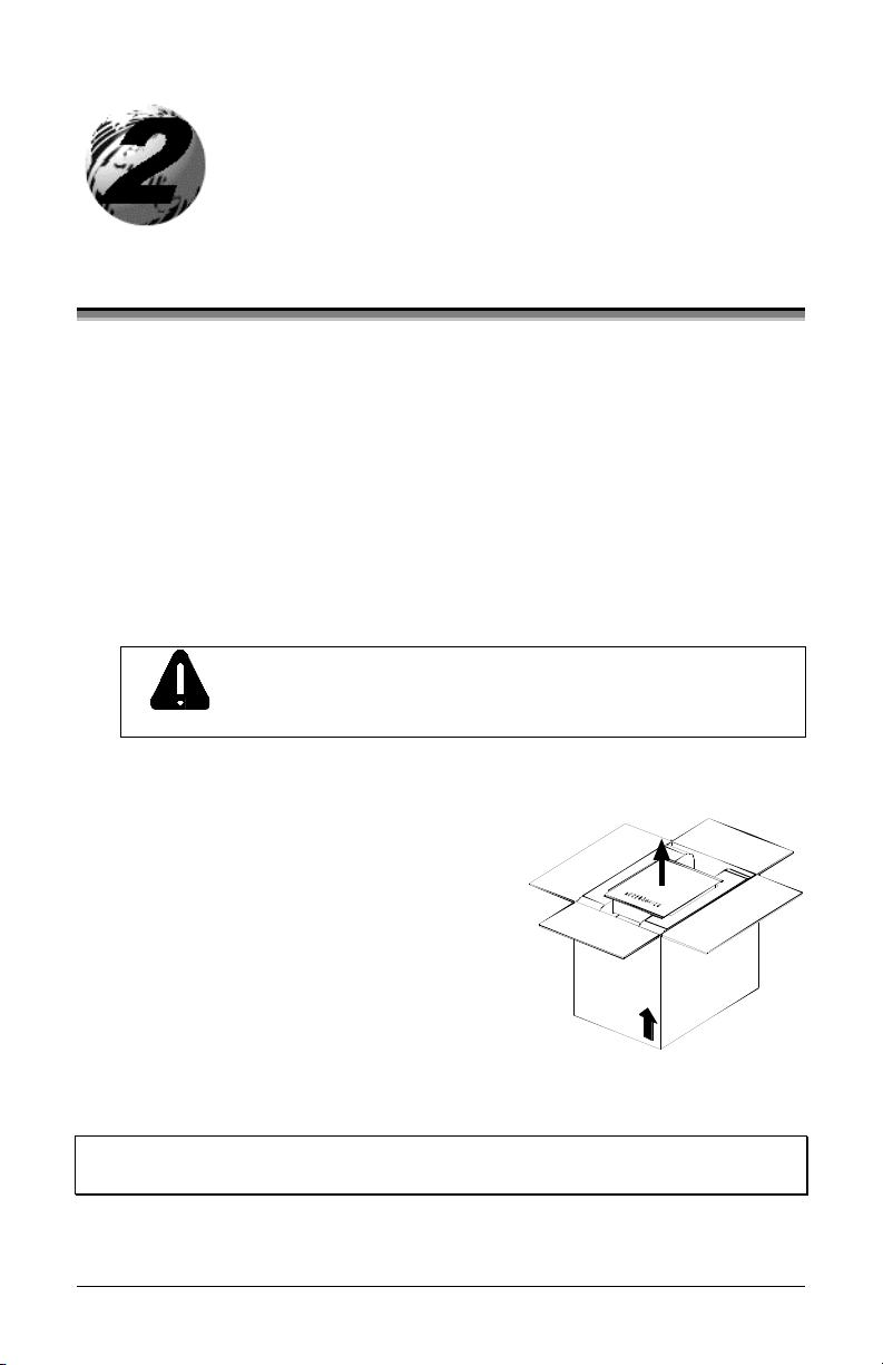
ΠCarefully open the shipping container and remove the printer.
Never rest the SV model printer “end-down” on any
surface. Damage to the connectors on the bottom of
CAUTION
• Remove the printer from the plastic shipping bag.
Ž Carefully remove the tape that
extends over the Printhead Latch.
(On SV Model printers also remove
the tape that covers the interface
connectors.)
the printer can occur.
þ Note: Save all packaging materials in the event that shipping the
printer is ever required.
ST/SV-3210 and ST/SV-3306 5
Page 16
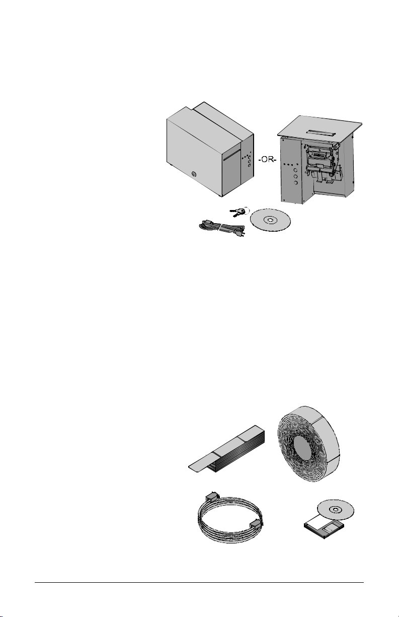
2.0.1 Inspection
After removing and inspecting the printer, check the remaining contents
of the container. In addition to this manual, the following items should be
included:
Ø Ticket Printer
Ø Power cord
Ø Keys (ST Models only)
Ø Accessories CD
Ø Special or additionally
purchased items.
2.0.2 Additional Requirements
The following items are necessary for generating printed tickets using the
printer. For advice on which stock and software is best suited for your
needs, contact your customer representative.
Ø Serial or parallel interface cable
Ø Applicable ticket stock
Ø Applicable software
6 ST/SV-3210 and ST/SV-3306
Page 17
This section details the connections, loading methods, memory module
installation, and resident ticket formats of the printer.
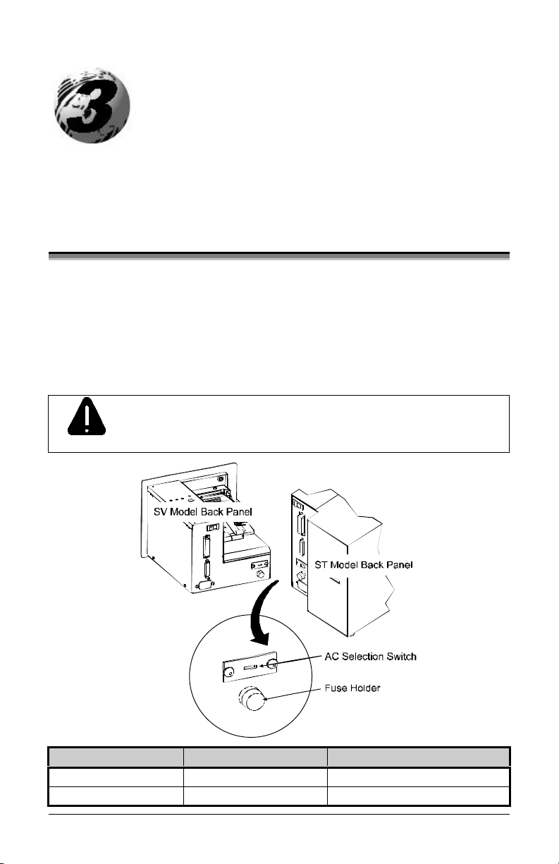
3.0 AC Voltage Configuration
Depending upon the configuration of the AC Selection Switch and fuse,
the printer is capable of either 115 or 230 VAC single-phase operation.
Before connecting power, check the voltage configuration: (1) locate the
AC Selection Switch and Fuse Holder (containing the fuse) on the Back
Panel, then (2) referencing the table below, ensure that the AC Selection
Switch setting and fuse rating correspond to your AC Source Voltage.
Failure to verify the AC Selection Switch setting and fuse
rating can result in personal injury and/or printer damage.
CAUTION
AC Source Voltage AC Selection Switch Required Fuse Rating
105 – 125 VAC 115 VAC 1.6 amp / 250V slow-blow
210 – 250 VAC 230 VAC 0.8 amp / 250V slow-blow
ST/SV-3210 and ST/SV-3306 7
Page 18

3.1 Interfacing the Printer
Interfacing the printer to the host computer can be made through either a
parallel or a serial cable (see Appendix C for cable requirements).
Communication port selection is automatic: the first port to receive data
is set ‘active’ by the printer. To change an active port, cycle the power
‘Off’ and ‘On’ or perform a Warm Reset (see Section 3.6.1).
Parallel Interface Port:
The parallel interface supports Centronics parallel communications.
Serial Interface Port:
The serial interface supports either RS-232 or RS-422 communications.
The following menu-selectable serial port settings must be configured to
match those of the host computer; see Section 4.3.
• Baud Rate
• Word Length (including Parity, which defaults to either of the
following):
8-bit word with no parity
7-bit word with even parity
þ Note: If unable to establish communications, see Section 5 for help.
8 ST/SV-3210 and ST/SV-3306
Page 19
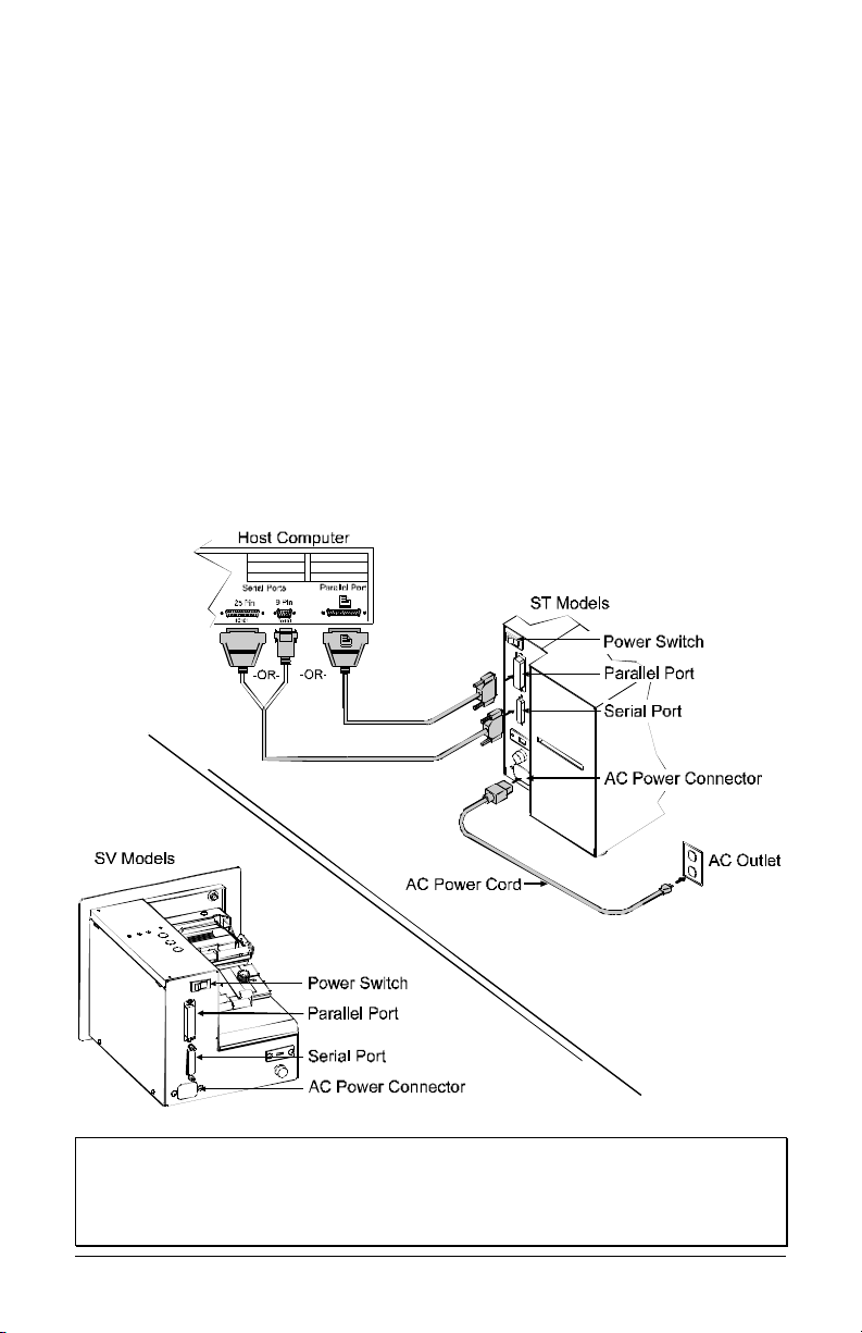
Printer power and interface connections:
Follow these instructions to connect the printer.
Œ Turn ‘Off’ the power to the Host Computer.
• Verify that the Printer’s AC Configuration has been set; see Section
3.0.
Ž Connect the interface cable securely between the Printer and Host
communication ports.
• Verify that the Power Switch is in the ‘Off’ position and connect the
AC Power Cord to the AC Power Connector, then to the AC Outlet.
• Turn ‘On’ the Printer and then the Host Computer.
þ Note: Ensure the printer’s Power Switch is ‘Off’ before connecting
the AC Power Cord or the interface cable; also, turn ‘Off’ the
power to the host system before connecting the interface
cable.
ST/SV-3210 and ST/SV-3306 9
Page 20
3.2 Loading Ticket Stock
Both printers feature an automatic ticket loading and positioning
mechanism, although the initial loading instructions differ slightly
according to model and options.
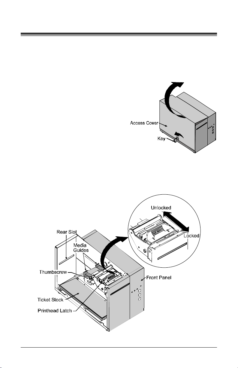
3.2.1 ST Models
Œ Plug in and turn ‘On’ the printer.
• Insert the Key and unlock the
Access Cover.
Ž Raise the Access Cover (for
convenience the cover may be
removed by sliding it forward and
then up).
• Place fanfold ticket stock (with the TOF Mark facing down; see
Section 4.0) in the bottom of the printer or if using an external
supply, route the stock through either the Bottom or Rear Slots.
(Continued next page)
10 ST/SV-3210 and ST/SV-3306
Page 21
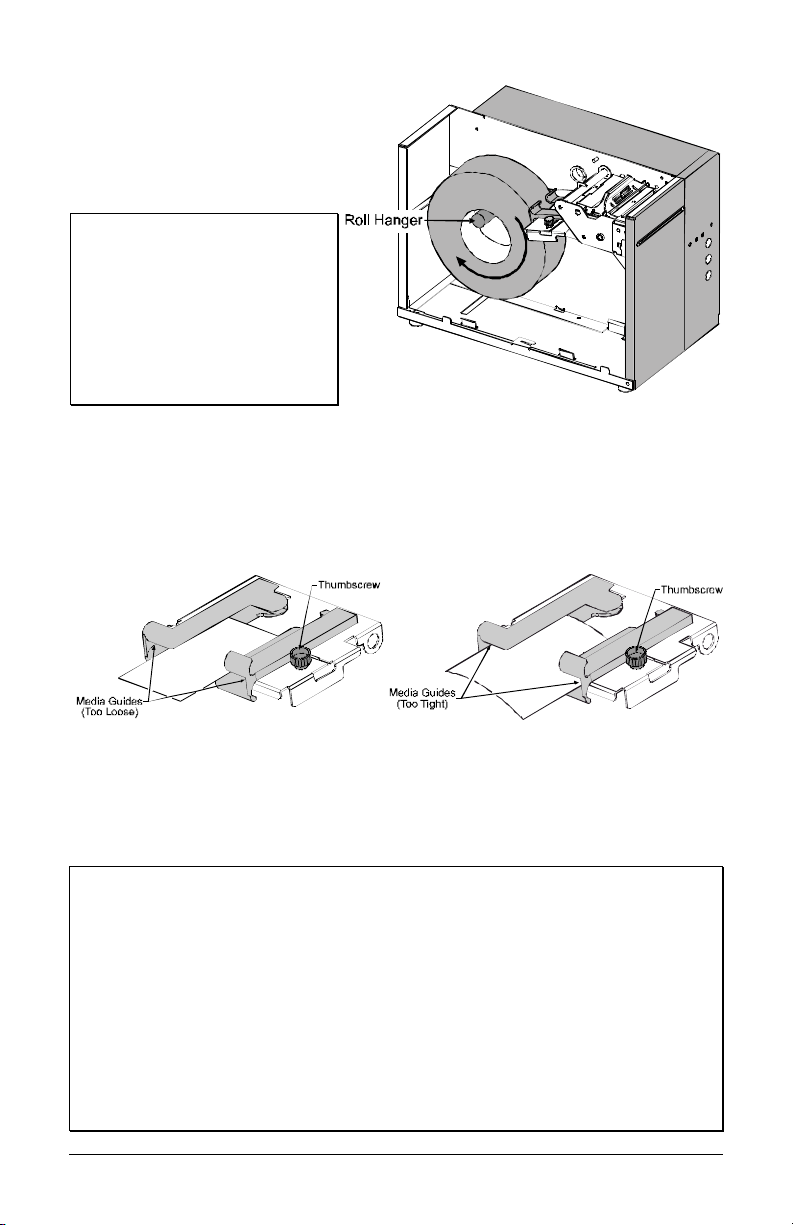
To use roll ticket stock, the
stock must be mounted on
the optional Roll Hanger, as
shown. (See Section 6 for
stock requirements.)
þ Note: To use an internal
fanfold ticket source on a
printer equipped with the
Roll Hanger option, first
remove the Roll Hanger by
unscrewing it from the
printer. Store the hanger in
a safe place for future use.
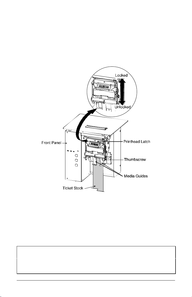
• Loosen the Thumbscrew and adjust the Media Guides to fit the width
of the ticket stock: the guides should be positioned close enough to
stop side-to-side ticket movement, but not so tight to cause friction
or bowing of the ticket stock (see below). Tighten the Thumbscrew
to secure the guides in place.
‘ Slide the ticket stock through the Media Guides. The motor will
start; continue sliding the tickets. The printer will grab the leading
edge of the stock and complete the positioning process. Close the
Access Cover.
þ Notes: If automatic loading doesn’t occur:
1) Ensure that the Printhead Latch is locked.
2) Press the PAUSE button (the On-Line Indicator should be ‘Off’
now).
3) Repeatedly press the F2 button while gently pushing the stock
forward until the printer grabs the ticket.
4) Press the PAUSE button (to return to the on-line mode).
If the ticket was not fed to a proper position, the TOF Sensor may need
adjustment; see Section 4 for details.
ST/SV-3210 and ST/SV-3306 11
Page 22
3.2.2 SV Models
Œ Plug in and turn ‘On’ the printer.
• Place fanfold ticket stock in the bottom of the enclosure, bring the
stock up to the Media Guides. (The TOF Mark should be facing
away from the Printhead Latch; see Section 4.) Ensure that the
Printhead Latch is locked.
Ž Loosen the Thumbscrew and adjust the Media Guides to fit the width
of the ticket stock as described in Step 5 of Section 3.2.1.
• Slide the ticket stock through the Media Guides. The motor will
start; continue feeding the tickets. The printer will grab the leading
edge of the stock and complete the positioning process. If this
process fails, see the note below.
þ Notes: If automatic loading fails to occur, see the note at the end of
Section 3.2.1.
If the ticket did not feed to a proper position, the TOF Sensor
may need adjustment; see Section 4 for details.
12 ST/SV-3210 and ST/SV-3306
Page 23
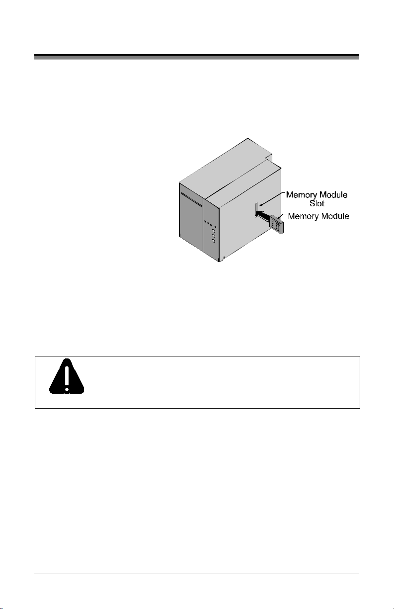
3.3 Installing a Memory Module
Optional Flash Memory Modules offer convenient, non-volatile storage
of formats, fonts and graphics. Refer to the DPL Programmer’s Manual
(part number 88-2051-01) for programming and use details. To install a
module:
Œ Turn ‘Off’ the printer.
• Place the Memory Module’s
‘write protect’ switch into
the desired position (in
the ‘On’ position the
module cannot be
written to).
Ž Carefully insert the
Memory Module into the
Memory Module Slot.
• Turn the printer ‘On’.
To avoid damage to the Memory Module or the printer,
only use modules designed for this printer and always
CAUTION
ST/SV-3210 and ST/SV-3306 13
turn the printer ‘Off’ before inserting or removing the
module.
Page 24
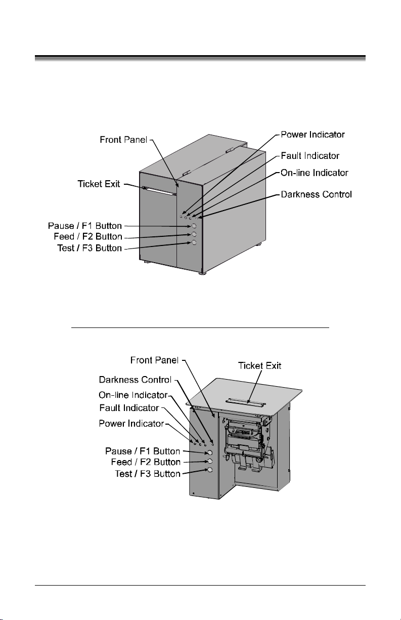
3.4 Using the Front Panel
The Front Panel on both models is comprised of a ticket exit, darkness
control, three indicator lights, and three dual-purpose buttons.
ST Models
SV Models
(Continued next page)
14 ST/SV-3210 and ST/SV-3306
Page 25

Ticket Exit
The printed tickets are expelled from this opening.
Darkness Control
The Darkness Control will adjust the darkness of the printing on the
tickets: turning the control clockwise darkens the print and turning the
control counterclockwise lightens the print. This darkness function can
also be controlled through software commands.
Indicators
For a brief period (approximately 20 seconds) after power-up, all three
indicators will remain on while the printer performs internal diagnostics.
POWER:
Turning ‘On’ the power switch lights this indicator.
FAULT:
During normal operation, this indicator will flash briefly as
the printer receives data from the host system; however, if a
fault is detected this indicator stays on. A fault can have
several different causes; see Section 5 for details.
ON-LINE:
In the on-line mode, this indicator lights to denote that the
printer is ready to accept data. Pressing the PAUSE button
while tickets remain to print causes the indicator to flash
repeatedly. This indicator remains off in the off-line mode.
Dual-Purpose Buttons
Depending upon the printer’s mode, the buttons function as follows:
On-Line Mode Button Functions (the On-Line Indicator is ‘On’)
PAUSE:
Press this to temporarily stop printing (pause mode) or to
enter the off-line mode.
Press this button in pause mode to resume printing from the
point stopped; or, if in off-line mode press to return to the
on-line mode.
FEED:
TEST:
Press this button to advance the ticket stock to the next print
position.
This button is inactive in the on-line mode.
ST/SV-3210 and ST/SV-3306 15
Page 26

Power-Up and Off-Line Mode Button Functions (the On-Line
Indicator is ‘Off’)
Ø F2:
Three functions:
(a) Press momentarily to advance ticket stock, or to
manually load ticket stock.
(b) Press and hold during power-up to print a
Configuration and Test Pattern Ticket, and enter
Character Dump mode.
(c) Press and hold to enter the Operational Database
Modification mode; see Section 4.3 for details.
Ø F3:
Two functions:
(a) Press and hold to enter the Start of Print and
Cut/Tear Adjustments; see Section 4.2 for
details.
(b) Press momentarily to print an Internal Test
Ticket; see Section 3.5.3.
Ø F1 + F3:
Press these simultaneously to perform a Warm Reset
and return to the on-line mode.
Ø F1 + F2:
Press these simultaneously to print a Test Pattern
Ticket; see Section 3.5.2.
Ø F2 + F3:
Press these simultaneously to print a Configuration
Ticket; see Section 3.5.1.
Ø F1 + F2 + F3:
Press and hold these during power-up to reset the
printer to the default settings; see Section 3.6.2.
16 ST/SV-3210 and ST/SV-3306
Page 27

3.5 Resident Formats
Stored within the memory are several ticket formats that provide useful
setup, operational, and problem diagnosis information. Load stock that is
at least 2 inches (51 mm) wide to capture all the data on these resident
formats.
3.5.1 Configuration Ticket
The Configuration Ticket provides memory, firmware, and installed
options information (depending upon the printer model, options, and age
this information will vary). To print a Configuration Ticket:
ΠWith stock loaded, turn the
printer ‘On’.
• Press the PAUSE button to
enter the off-line mode.
Ž Simultaneously press the F2
and F3 buttons.
Operational data is also provided:
Basic setup including speed
settings, Stock ID, and the start of
print and cut/tear positions.
Counter Information provides time
of operation and amount printed.
(The Resettable Values counter can
be used for tracking job data; see
the DPL Programmer’s Manual
for details.)
The Input Values section indicates
the Parser Mode setting; also
included here are the sensor A-D
values, which are used for internal
system control functions.
ST/SV-3210 and ST/SV-3306 17
Page 28

3.5.2 Test Pattern Ticket
The Test Pattern Ticket is a resident format that can be used to determine
general print quality and the condition of the printhead.
Œ With stock loaded, turn the printer ‘On’.
• Press the PAUSE button to put the printer in the off-line mode.
Ž Simultaneously press the F1 and F2 buttons.
A “Good” Test Pattern Ticket:
Consistent print patterns across
the width of the ticket indicate
that the printhead is operating
normally.
A “Faulty” Test Pattern Ticket:
Streaks (vertical lines of missing
print) indicate a dirty or faulty
printhead. See Section 4.4.1 for
cleaning instructions.
þ Note: The Test Pattern Ticket is generated at the preset Darkness
and Speed settings. Adjust these accordingly or use a ticket
format generated from the host for final print quality
assessments.
18 ST/SV-3210 and ST/SV-3306
Page 29

3.5.3 Internal Test Ticket
The Internal Test Ticket is another resident format that is another useful
indicator of print quality. This ticket features various font sizes and
barcodes (the sample below was printed using the ST-3210). To print an
Internal Test Ticket:
Œ With stock loaded, turn the printer ‘On’.
• Press the PAUSE button to enter the off-line mode.
Ž Press the F3 button.
ST/SV-3210 and ST/SV-3306 19
Page 30

3.6 Resetting the Printer
There are two different reset levels possible for the printer:
3.6.1 Warm Reset
To reset the printer and return to the on-line mode: Press the PAUSE
button to go off-line and then press the F1 + F3 buttons simultaneously.
3.6.2 Factory Default Reset
To return the printer to default database settings (see the table below),
perform the following procedure.
Œ Turn the printer ‘Off’.
• Press and hold the PAUSE/F1, FEED/F2 and TEST/F3 buttons while
turning ‘On’ the printer.
Ž After the Fault Indicator flashes (approximately 20 seconds), release
all three buttons.
For verification, a Configuration Ticket can be printed. The printout will
reflect default settings until new configuration data is sent to the printer.
Default Database Settings
Function ST/SV 3210 Values ST/SV 3306 Values
Memory Configuration:
Internal Module
Scalable Fonts
Character Set:
(DPL parser mode only)
Cutter Auto Detect Auto Detect
Parser Mode:
Print Speed:
Slew Speed:
Backup Speed:
[2]
[3]
[3]
[3]
Stock ID 5 5
Print Width 1.89 inches (48 mm) 1.92 inches (49 mm)
[1]
Memory allocations are represented in 4KB units each and modifiable only when in the
DPL parser mode.
[2]
The parser mode setting may arrive factory-configured to meet your application;
otherwise see Section 4.3.1.
[3]
All speed values given in Inches Per Second.
20 ST/SV-3210 and ST/SV-3306
[1]
128
64
128
64
Standard Standard
DTPL DTPL
8 4
8 4
3 3
Page 31

Adjusting and
Maintaining the Printer
This section details important adjustments, settings and periodic
maintenance requirements that will ensure optimum printer performance.
4.0 TOF Sensor Adjustment
The TOF Sensor in the printer has two functions: (1) sensing the
presence of ticket stock and (2) when using reflective stock, sensing the
Top of Form (TOF) Mark on each ticket. If the ticket stock does not
contain TOF Marks, DPL programming must be used to set the ticket
size.
To advance tickets correctly,
the sensor must be positioned
under the TOF Mark and
within in a Quiet Zone (an area
free of preprinted text or
logos); see Section 6 for stock
requirements.
þ Note: Preprinted text and logos can cause false TOF readings.
Depending upon the printer model, the adjustment of the TOF Sensor
differs slightly.
ST/SV-3210 and ST/SV-3306 21
Page 32

4.0.1 ST Model TOF Sensor Adjustment
ΠInsert the Key and unlock the Access Cover.
• Raise the Access Cover. (For convenience, the cover may also be
removed by sliding it forward and then off.)
Ž Unlock the Printhead Latch and raise the Printhead Assembly.
• Grasp the Slide and move it ‘in’ or ‘out’ accordingly, so the position
of TOF Sensor is underneath the TOF Mark and within a quiet zone
area of the ticket stock.
• Lower the Printhead Assembly and lock the Printhead Latch.
‘ Re-feed the ticket stock; see Section 3.2.
’ Lower and lock the Access Cover.
22 ST/SV-3210 and ST/SV-3306
Page 33

4.0.2 SV Model TOF Sensor Adjustment
ΠUnlock and raise the Printhead Assembly.
• Grasp the TOF Sensor and move it ‘in’ or ‘out’ accordingly, to
position the sensor underneath the TOF Mark and within a quiet zone
area of the ticket stock.
Ž Lower the Printhead Assembly and lock the Printhead Latch.
• Re-feed the ticket stock; see Section 3.2.
ST/SV-3210 and ST/SV-3306 23
Page 34

4.1 Stock ID Selections
The printer maintains a selection of 10 user modifiable stock setups.
Each setup defaults to a specific print width, start print position and
cut/tear position, where:
Ø The Print Width is the print distance
across the ticket.
Ø The Start of Print Position is the
distance, measured in inches, from the
TOF Sensor to printhead burnline.
Ø The Cut/Tear Position is the distance,
measured in inches, from the TOF
Sensor to the cut (if equipped) or tear
position of the printed ticket.
The Stock ID can be set using the
Operational Database Modification
procedure (see Section 4.3.1). As defined on
the following page, Stock ID numbers 0
through 8 are not changeable through host
commands; however, Stock ID 9 will allow
host commands to override the default
settings.
If none of the listed Stock ID selections fit your media, select the Stock
ID that is closest to the physical dimensions of your stock and then
modify the Start of Print and Cut/Tear positions (see Section 4.2). All
changes can be saved to the Stock ID, allowing commonly used formats
to be recalled. To revert to the default values, reset the printer (see
Section 3.6).
24 ST/SV-3210 and ST/SV-3306
Page 35

The table below lists the default settings, according to the printer model, for each Stock ID number.
Stock ID
Stock ID Default Settings
Print Width
3210 Models 3306 Models
Start of Print
Position
Cut/Tear
Position*
0 3.15" (80.0 mm) 3.20" (81.3 mm) .07" (1.8 mm) .05" (1.3 mm)
1 3.15" (80.0 mm) 3.20" (81.3 mm) 4.28" (108.7 mm) 4.26" (108.2 mm)
2 3.15" (80.0 mm) 3.20" (81.3 mm) 1.67" (42.4 mm) 1.65" (41.9 mm)
3 3.15" (80.0 mm) 3.20" (81.3 mm) .02" (.5 mm) 0
4 1.89" (48.0 mm) 1.81" (46.0 mm) .02" (.5 mm) 0
5 1.89" (48.0 mm) 1.92" (48.8 mm) 4.33" (110.0 mm) 4.30" (109.2 mm)
6 1.89" (48.0 mm) 1.92" (48.8 mm) 1.70" (43.2 mm) 1.67" (42.4 mm)
7 1.89" (48.0 mm) 1.92" (48.8 mm) 1.45" (36.8 mm) 1.42" (36.1 mm)
8 2.20" (55.9 mm) 2.24" (56.9 mm) .07" (1.8 mm) .05" (1.3 mm)
9 3.15" (80.0 mm) 3.20" (81.3 mm) 0 0
*For SV Model printers using the Tear Bar: Add .07 inch (1.8mm) to these distances for Top Plate clearance of the ticket.
ST/SV-3210 and ST/SV-3306 25
Page 36

4.2 Start of Print & Cut/Tear Adjustment
If none of the preset Stock ID parameters meet the needs of your
application, then the Start of Print (SOP) and Cut/Tear (C/T)
Adjustments can be used to visually set the required positions. To begin:
ΠIf on-line, press the PAUSE button
to place the printer off-line.
• Press and hold (approximately 6
seconds) the F3 button until the OnLine Indicator is lit then release.
The SOP setup is first, to adjust:
Ø Press the F1 button to increase the current distance (pressing
and holding will rapidly move the ticket).
Ø Press the F2 button to decrease the current distance (pressing
and holding will rapidly move the ticket).
Ø Press the F3 button to print a ticket showing the new setting.
Ž After completing the SOP adjustment, press and hold (approximately
6 seconds) the F3 button until the On-Line Indicator is lit then
release.
• Next, adjust the Cut/Tear position
using the F1, F2 and F3 buttons as
described above.
• After completing the Cut/Tear
adjustment, return the printer to
the off-line mode by pressing and
holding the F3 button until the On-Line Indicator is lit then release.
‘ Press the PAUSE button to return to the on-line mode.
þ Notes: This procedure must be performed in its entirety, even when
no change is desired for one of the settings.
After completing the adjustments, always confirm the new
settings by printing several test tickets.
If cutting, the cut position on the ticket should occur
just behind the perforation, never in front of the
perforation.
26 ST/SV-3210 and ST/SV-3306
Page 37

4.3 Operational Database Modification
The operational database for the printer, which contains the parser mode
setting and other important printer parameters, can be changed using the
front panel. To change the Operational Database settings:
ΠIf on-line, press the PAUSE button to place the printer off-line.
• Press and hold the F2 button until the On-Line Indicator is lit
(approximately six seconds) then release. To adjust:
Ø Press the F1 button to advance to the next setting of the
current item, print the selection, and present it for
acceptance.
Ø Press the F2 button to accept the presented item and
value for use then print and present the next item, or
press and hold the F2 button (until the On-Line Indicator
is lit) to cause a Warm Reset, apply the new settings, and
place the printer on-line.
Ø Press the F3 button to return to the previous setting for
the current item, print the selection, and present it for
acceptance.
The following pages contain tables listing the settings and values that are
accessible and modifiable through this method, while next subsection is
included to provide a systematic example of the database modification
procedure.
ST/SV-3210 and ST/SV-3306 27
Page 38

Operational Database: ST/SV-3210 Models
Parameter Description Settings
Stock ID Stock ID number 0-9 (see Section 4.1)
Label (Ticket)
Width
Width of the ticket stock used
for printing.
1.89 inches (48.0 mm)
2.04 inches (51.8 mm)
2.20 inches (55.9 mm)
2.36 inches (59.9 mm)
2.52 inches (64.0 mm)
2.67 inches (67.8 mm)
2.83 inches (71.9 mm)
2.99 inches (75.9 mm)
3.15 inches (80.0 mm)
Parser Mode Sets the emulation of the printer DTPL or DPL
Print Speed* Speed during printing 4-10 IPS
Slew Speed* Speed during feeding 4-10 IPS
Backup Speed* Speed during backup 3-5 IPS
Baud Rate Serial communication speed 600, 1200, 2400, 4800,
9600, 19.2K, 38.4K
Word Length Communicated word length 7-bit word (even parity)
8-bit word (no parity)
Cutter Equip Presence of the optional cutter
AUTO
will be sensed automatically.
Row Adjust** Horizontal adjustment of the
point where printing begins.
Col Adjust** Vertical adjustment of the point
where printing begins.
SOP Adjust Start of Print Position
Adjustment (see Section 4.2)
C/T Adjust Cut/Tear Position Adjustment
(see Section 4.2)
*Rates given in Inches Per Second.
** Valid in the DTPL Parser Mode only.
-2.55 – 2.55 inches
(-64.8 mm – 64.8 mm)
-2.55 – 2.55 inches
(-64.8 mm – 64.8 mm)
0 – 10.00 inches
(0 – 254 mm)
0 – 10.00 inches
(0 – 254 mm)
28 ST/SV-3210 and ST/SV-3306
Page 39

Operational Database: ST/SV-3306 Models
Parameter Description Settings
Stock ID Stock ID number 0-9 (see Section 4.1)
Label Width Width of the ticket stock used
for printing.
Parser Mode Sets the emulation of the printer DTPL or DPL
Print Speed* Speed during printing 2-6 IPS
Slew Speed* Speed during feeding 2-6 IPS
Backup Speed* Speed during backup 3-5 IPS
Baud Rate Serial communication speed 600, 1200, 2400, 4800,
Word Length Communicated word length 7-bit word (even parity)
1.81 inches (46.0 mm)
1.92 inches (48.8 mm)
2.03 inches (51.6 mm)
2.14 inches (54.4 mm)
2.24 inches (56.9 mm)
2.35 inches (59.7 mm)
2.46 inches (62.5 mm)
2.56 inches (65.0 mm)
2.67 inches (67.8 mm)
2.88 inches (73.2 mm)
2.99 inches (75.9 mm)
3.10 inches (78.7 mm)
3.20 inches (81.3 mm)
9600, 19.2K, 38.4K
8-bit word
Cutter Equip Presence of the optional cutter
will be sensed automatically.
Row Adjust** Horizontal adjustment of the
point where printing begins.
Col Adjust** Vertical adjustment of the point
where printing begins.
SOP Adjust Start of Print Position
Adjustment (see Section 4.2)
C/T Adjust Cut/Tear Position Adjustment
(see Section 4.2)
*Rates given in Inches Per Second.
** Valid in the DTPL Parser Mode only.
(-64.8 mm – 64.8 mm)
(-64.8 mm – 64.8 mm)
AUTO
-2.55 – 2.55 inches
-2.55 – 2.55 inches
0 – 10.00 inches
(0 – 254 mm)
0 – 10.00 inches
(0 – 254 mm)
(no
parit
y)
ST/SV-3210 and ST/SV-3306 29
Page 40

4.3.1 Database Modification Example
This section details the modification of an Operational Database
parameter. The following example increases the printing speed parameter
from 6 to 8 IPS on the ST-3210; however, using the same basic
procedure, any of the parameters can be changed regardless of the printer
model.
ΠIf on-line, press the PAUSE button to place the printer off-line.
• Press and hold the F2 button until the On-Line Indicator is lit
(approximately six seconds) then release.
The printer will turn off the
On-Line Indicator and
STOCK ID = 5
print:
Ž Press the F2 button three times (allow time for printing following
each button press), to arrive at the Print Speed parameter.
The printer will print:
PRINT SPEED = 6 IPS
PARSER MODE = DTPL
TICKET WIDTH = 189 (48 MM)
STOCK ID = 5
• Press the F1 button two times (again, allow time for printing
following each button press), to arrive at the 8 IPS setting.
The printer will print:
PRINT SPEED = 8 IPS
PRINT SPEED = 7 IPS
PRINT SPEED = 6 IPS
PARSER MODE = DTPL
TICKET WIDTH = 189 (48 MM)
STOCK ID = 5
• To save the changes and exit the mode, press and hold the F2 button
until the On-Line Indicator is lit (approximately six seconds) then
release.
The parameter changes can be confirmed by printing a Configuration
Ticket; see Section 3.5.1.
30 ST/SV-3210 and ST/SV-3306
Page 41

4.4 Maintenance
Routine maintenance will ensure the optimum performance of the printer.
The following table outlines the recommended cleaning intervals, while
the items listed below will help do the job safely and effectively:
• Isopropyl alcohol • Soft-bristle brush
• Cotton swabs • Soapy water/mild detergent
• A clean, lint-free cloth • Compressed air
For your continued safety and to avoid damage to the unit,
always turn ‘Off’ and unplug the printer before servicing.
Isopropyl alcohol is a flammable liquid, always take the
CAUTION
Area Method Interval
Printhead A cotton swab dampened with isopropyl alcohol,
proper precautions when using this solvent.
Recommended Cleaning Schedule
wiped across the printhead until all build-up is
removed. See Section 4.4.1.
After each
roll or box
of tickets.
Platen
Roller
TOF Sensor A brush or compressed air (and isopropyl alcohol,
Ticket Detect
Sensor
Ticket Path A brush or compressed air to remove all build-up
Interior
(ST Models
only)
Exterior A soft cloth dampened with a mild detergent to
Cutter
(optional
equipment)
ST/SV-3210 and ST/SV-3306 31
A cotton swab dampened with isopropyl alcohol
wiped across the platen roller. Rotate the roller by
hand and repeat to clean entire surface. See
Section 4.4.2.
if necessary) to remove all dust build-up. See
Section 4.4.3.
Compressed air to remove all dust build-up. See
Section 4.4.4.
along the paper path.
A brush or compressed air to remove all build-up
in the ticket compartment. See Section 4.4.5.
remove all build-up. See Section 4.4.6.
A brush or compressed air to remove all build-up. As needed.
After each
roll or box
of tickets.
Monthly
or as
needed.
As needed.
As needed.
As needed.
As needed.
Page 42

4.4.1 Cleaning the Printhead
Declining print quality (i.e., dropouts, streaking, or smudging) is usually
caused by a surface build-up of dirt on the printhead; see Section 3.5.2
for an example. Left unattended, this build-up can lead to permanent
printhead damage. To clean:
Œ Turn ‘Off’ and unplug
the printer.
• ST Models: Raise the
access cover; see
Section 3.2.
Ž Slide the Printhead
Latch to the Unlocked
position then raise the
Printhead Assembly.
• Gently clean the Printhead, including the Burnline, using a cotton
swab moistened with isopropyl alcohol to remove all build-up.
• Allow to dry; then lower the Printhead Assembly and slide the
Printhead Latch forward to the Locked position.
‘ ST Models: Close the access cover.
’ Plug in and turn ‘On’ the printer.
þ Note: NEVER use a sharp object to clean the Printhead.
32 ST/SV-3210 and ST/SV-3306
Page 43

4.4.2 Cleaning the Platen Roller
Print quality can decline if the platen roller becomes contaminated with
paper dust, grit or adhesive. When this build-up is not removed, it can
cause abrasive damage to the printhead. To clean the Platen Roller:
Œ Turn ‘Off’ and unplug the printer.
• ST Models: Raise the access cover; see Section 3.2.
Ž Slide the printhead latch to the unlocked position, raise the Printhead
Assembly (see Section 4.4.1) and remove the ticket stock.
• Using a cotton swab or lint-free cloth moistened with isopropyl
alcohol, remove all debris from the Platen Roller. Manually rotate
the roller and repeat to clean the entire surface.
• Allow the Platen Roller to dry, then lower the Printhead Assembly
and slide the printhead latch into the locked position.
‘ Plug in and turn ‘On’
the printer.
’ Load ticket stock;
see Section 3.2.
“ ST Models: Close the
access cover.
þ Note: NEVER use a sharp object to clean the Platen Roller.
ST/SV-3210 and ST/SV-3306 33
Page 44

4.4.3 TOF Sensor Cleaning
If the TOF Sensor becomes blocked with paper particles, Top of Form
detection can be inconsistent or fail completely. To clean the sensor:
Œ Turn ‘Off’ and unplug the printer.
• ST Models: Raise the access cover; see Section 3.2.
Ž Slide the printhead latch to the unlocked position, raise the Printhead
Assembly (see Section 4.4.1) and remove the ticket stock.
• Using a soft brush or compressed air, remove any debris
accumulated on the TOF Sensor. (If necessary, an isopropyl alcohol
dampened cotton swab can be used to remove build-up.)
• If necessary allow the sensor to dry, then lower the Printhead
Assembly and slide the printhead latch into the locked position.
‘ Plug in and turn ‘On’ the printer.
’ Load ticket stock (see Section 3.2).
“ ST Models: Close the access cover.
34 ST/SV-3210 and ST/SV-3306
Page 45

4.4.4 Ticket Detect Sensor Cleaning
The Ticket Detect Sensor initiates the auto-loading process by signaling
the presence of ticket stock within the Media Guides. If the sensor
becomes blocked with paper particles, ticket feeding problems can occur.
To clean the sensor:
Œ Turn ‘Off’ and unplug the printer.
• ST Models: Raise the access cover; see Section 3.2.
Ž Slide the printhead latch to the unlocked position, raise the printhead
assembly (see Section 4.4.1) and remove the ticket stock.
• Using compressed air, direct the airflow between the Media Guide
and under the area indicated by the dotted line in the drawing below.
(The sensor resides in a small aperture within the Media Guide.)
• Lower the Printhead Assembly and slide the printhead latch into the
locked position.
‘ Plug in and turn ‘On’ the printer.
’ Load ticket stock (see Section 3.2).
“ ST Models: Close the access cover.
ST/SV-3210 and ST/SV-3306 35
Page 46

4.4.5 Interior Cleaning
ST Models only: Ticket Compartment Cleaning
During normal operation, paper particles from the ticket stock
accumulate inside the printer. These particles can stick to the ticket and
cause voids in the print, reducing print quality. To clean the interior of
the printer:
Œ Turn ‘Off’ and
unplug the printer.
• Raise the access
cover; see Section
3.2.
Ž Slide the printhead
latch to the
unlocked position,
raise the Printhead Assembly (see Section 4.4.1) and remove the
ticket stock.
• Using a soft brush or compressed air, remove all debris accumulated
inside the ticket compartment.
• Plug in and turn ‘On’ the printer.
‘ Load ticket stock (see Section 3.2).
’ Close the access cover.
4.4.6 Exterior Surface Cleaning
The exterior surface can be cleaned using a general purpose cleaner and a
soft cloth or sponge. Never use abrasive cleansers or solvents. To clean:
Œ Turn ‘Off’ and unplug the printer.
• Gently wipe the exterior surfaces until clean and then allow time to
dry.
Ž Plug in and turn ‘On’ the printer.
36 ST/SV-3210 and ST/SV-3306
Page 47

Troubleshooting
5.0 Troubleshooting Tips
This section addresses common problems and suggests solutions. While
not all situations can be addressed, many suggestions may prove helpful;
however, if a problem persists or is not covered in this text, contact
Datamax Technical Support or a qualified service technician.
þ Note: If the Fault Indicator is lit, the FEED button must be pressed
to clear the alarm after completing the corrective action.
If experiencing this problem… Try this solution…
The printer fails to power-up:
Ÿ The AC voltage configuration for the
printer may be incorrect; see Section
3.0. (If connected while incorrectly
configured, the line fuse may be blown
as a result; call for service.)
Ÿ The AC power cord may be faulty; try
another cord.
Ÿ The AC outlet may be faulty; try
moving the printer to another wall
outlet.
All three indicator lights are ‘On’:
ST/SV-3210 and ST/SV-3306 37
Ÿ Ensure that the printer has been
configured to match the AC line
voltage; see Section 3.0.
Ÿ The printer has failed to initialize; call
for service.
Page 48

If experiencing this problem… Try this solution…
No Communications:
Poor print quality or no printing: Ÿ The printhead latch may not be locked;
Ÿ The parser mode setting between the
printer and host may not match;
reconfigure, see Section 4.3.
Ÿ The communication parameters between
the printer and host may not match;
reconfigure to match, see Section 4.3.
Ÿ The interface connection may be faulty
or the cable may be incorrect or faulty;
check the connections and see
Appendix C for cable requirements.
lock the latch. See Section 3.2.
Ÿ The printhead may be dirty; clean per
Section 4.4.1.
Ÿ The heat setting may be incorrect for the
stock. Use the Darkness Control (see
Section 3.4), or adjust the heat setting
through the software program (software
will override the Front Panel setting). In
addition, print speed can also be used to
darken or lighten print.
Ÿ The type of ticket stock may be
incorrect (i.e., thermal transfer).
Ÿ The parser mode setting between the
printer and the host may not match;
reconfigure for the same emulation, see
Section 4.3.
Ÿ The printhead latch may not be locked;
lock the latch. See Section 3.2.
Ÿ The printhead may be dirty; clean per
Section 4.4.1.
38 ST/SV-3210 and ST/SV-3306
Page 49

If experiencing this problem… Try this solution…
After printing the ticket, the
Fault Indicator lights:
The printer feeds when no ticket
stock is present or :
The printer feeds approximately
20 inches (51 cm) of ticket stock
then the Fault Indicator lights:
Tickets sometimes jam and/or
the printing is not square to the
ticket borders:
Ÿ If cutter equipped, this may indicate a
cutter fault; call for service.
Ÿ If not cutter equipped:
a) Possible programming problem.
b) Possible mechanical problem – try
pressing the FEED button to clear
the fault: if no response, call for
service. Otherwise, the positioning
of the TOF Sensor may need an
adjustment (see Section 4.0).
Ÿ The Ticket Detect Sensor may be
obstructed; clean the sensor per Section
4.4.4.
Ÿ The position of the TOF Sensor may
adjusting; see Section 4.0.
Ÿ The TOF Sensor may be obstructed;
clean the sensor, see Section 4.4.3.
Ÿ The TOF Mark on the ticket stock may
not meet specifications; see Section 6.
Ÿ Ticket stock may be mounted upside
down; reinstall correctly, see Section
3.2.
Ÿ The printhead may not be latched; see
Section 4.4.1.
Ÿ The Media Guides may be incorrectly
positioned; see Section 3.2.
Ÿ If cutter equipped, the cutter may be
malfunctioning; call for service.
ST/SV-3210 and ST/SV-3306 39
Page 50

If experiencing this problem… Try this solution…
The printer does not print
formats sent from the host, but
the Fault Indicator remains off:
Erratic print (strange characters
instead of ticket formats are
printed):
The cutter fails to cut, but the
Fault Indicator remains off:
• The parser mode setting between the
printer and host may not match;
reconfigure, see Section 4.3.1.
• The communication parameters between
the printer and host may not match;
reconfigure, see Section 4.3.1.
• The interface connection may be faulty
or the cable may be incorrect or faulty;
check the connections and see Appendix
C for cable requirements.
• The printer may be in ‘character dump
mode’ (see Section 5.1); cycle the
printer power ‘Off’ and ‘On’.
• The printer may be in ‘hex dump
mode’; see Section 5.1.
• If using the serial interface port, check
the host and printer communications
settings; see Section 3.5.1.
First verify the cutter has been detected by
printing a Configuration Ticket; see
Section 3.5.1:
• If the cutter has not been detected, call
for service; otherwise, verify that the
cut function has been selected in the
software program.
40 ST/SV-3210 and ST/SV-3306
Page 51

5.1 Hex Dump Mode
The hex dump mode is a useful tool for diagnosing problems, including
communication and programming syntax errors. This mode allows a
comparison of input strings to output data. Repeatedly sending a format
can uncover handshaking problems (identified by sections of missing
data in the output string). To decode this hexadecimal code and its
printable ASCII equivalents, the DPL Programmer’s Manual or the
DTPL Programmer’s Manual is an essential reference. As a final note,
many software programs use bit mapping to construct the ticket, making
diagnosis difficult. Contact a Datamax Technical Support Representative
with any questions.
To enter the Hex Dump Mode:
Œ With ticket stock loaded, turn ‘Off’ the printer.
• Press and hold the FEED button while turning ‘On’ the printer.
Continue to hold the button until the tickets feed forward.
After a brief hesitation, Configuration and Test Pattern Tickets will be
printed. After this, any data reaching the printer’s input buffer will be
output in hex/ASCII data, as follows:
þ Note: To exit the hex dump mode, cycle the printer power ‘Off’ and
‘On’.
ST/SV-3210 and ST/SV-3306 41
Page 52

42 ST/SV-3210 and ST/SV-3306
Page 53

Specifications
6.0 Specifications
Communications
Character Set: ANSI ASCII
Parallel Interface Port:
Serial Interface Port: RS-232c and RS-422; DB25
Baud Rates: 600, 1200, 2400, 4800, 9600, 19.2K and 38.4K
Word Length and Parity: Selectable data format:
Handshaking: Xon/Xoff and CTS & DTR.
Input Buffer: Serial: Approximately 6 Kbytes. XOFF is
Centronics type 36-pin
7-bit word with even parity, or
8-bit word with no parity
transmitted and DTR goes low with 750 bytes
available in the buffer. XON is transmitted and
DTR goes high when 1000 bytes remain in the
buffer. Characters are transmitted without
parity from the printer.
Parallel: 1KBytes.
Control (Front) Panel
Indicators: Power, Fault and On-Line.
Buttons: Dual Purpose: Pause/F1; Feed/F2; and Test/F3
Potentiometer: 0-20 darkness settings
Electrical
Input Voltage,
Configurable:
Circuit Protection: 115 VAC: 1.6A Time Delay Fuse.
Grounding: Unit must be connected to a properly grounded
ST/SV-3210 and ST/SV-3306 43
105 − 125 VAC, or
210 − 250 VAC; 47-63 Hz.
230 VAC: 0.8A Time Delay Fuse.
receptacle.
Page 54

Environmental
Operating Temperature: 40°F to 100°F (4°C to 38°C)
Storage Temperature: 32°F to 120°F (0°C to 49°C)
Humidity: 10% to 95% non-condensing
Ventilation: Free air movement
Dust: Non-conducting, non-corrosive
Electromagnetic Radiation: Moderate RF fields can be tolerated
Fonts/Barcodes (See Appendix B for examples)
Resident Fonts
(parser mode setting
dependent):
Optional Fonts: AGFA Scalable Font Engine supporting
Font Expansion and
Rotations:
Barcode Symbologies
(parser mode setting
dependent):
DPL mode: Nine alphanumeric fonts from
0.035"H (0.89mm) to 0.64"H (16mm),
including OCR-A and OCR-B; CG Triumvirate
Bitmap Font - DPL 9 in 4, 5, 6, 8, 10, 12, 14,
18, 24, 30, 36 point size fonts (point sizes 4 and
5 are available for ST/SV 3306 models only).
DTPL mode: 13 different typefaces and sizes.
downloads of Intellifont and True Type Font
formats.
All fonts expandable vertically and horizontally
up to 8x; fonts and graphics can be printed in
four directions: 0°, 90°, 180° and 270°.
DPL mode: Code 39, Interleaved 2 of 5, Code
128 (subsets A, B, and C), Codabar,
LOGMARS, UPC-A, UPC-E, UPC 2 & 5 digit
addendum's, EAN-8, EAN-13, EAN 2 & 5
digit addendum's, UPC random weight, Code
93, MSI Plessey, Universal Shipping Container
Symbology, Code 128 MOD 43, Postnet,
USS/EAN-128 random weight, Telepen, UPS
MaxiCode modes 2 & 3 (AIM specification,
June 18,1996) and PDF417.
DTPL mode: Code 39, Code 128 (subsets A, B,
and C), Interleaved 2 of 5, UPC-A, EAN-8,
EAN-13, and Codabar.
44 ST/SV-3210 and ST/SV-3306
Page 55

Mechanical
Width:
ST/SV-3210
ST/SV-3306
8.14 inches (20.7 cm)
8.05 inches (20.4 cm)
Depth:
ST/SV-3210
ST/SV-3306
14 inches (35.6 cm)
7.65 inches (19.4 cm)
Height:
ST/SV-3210
ST/SV-3306
10.5 inches (26.7 cm)
10.5 inches (26.7 cm)
Weight:
ST Models
SV Models
Top Plate:
SV Models only
Operating Temperature:
22 pounds (10 kg)
18.8 pounds (8.46 kg)
9.71 inches (24.7 cm) W X 8.60 inches (21.8
cm) DP X .09 inch (2.27 mm) THK
40° F to 100° F (4° C to 38° C)
Print Engine
Print Type: Direct Thermal
Print Resolution:
ST/SV-3210
ST/SV-3306
Nominal Printhead Dot Size:
ST/SV-3210
ST/SV-3306
Maximum Print Width:
ST/SV-3210
ST/SV-3306
Print Speed:
ST/SV-3210
ST/SV-3306
Slew Speed:
ST/SV-3210
ST/SV-3306
Back Speed:
*
203 DPI (8 dots/mm)
300 DPI (11.8 dots/mm)
.0043 inch X .0052 inch (.108 mm X .132 mm)
.0027 inch X .0043 inch (.069 mm X .110 mm)
3.15 inches (80 mm)
3.20 inches (81.3 mm)
**
3.5 –10 IPS (89 – 254 mm per second)
3.5 –6 IPS (89 – 152 mmps)
**
2.0 − 10.0 IPS (51 − 254 mmps)
2.0 – 6.0 IPS (51 – 152 mmps)
**
2.0 − 5.0 IPS (51 − 127 mmps)
Print Length Range: 12 inches (304.8 mm) at default settings.
Ticket Sensing: Moveable sensor
*
Given in Dots Per Inch
**
Given in Inches Per Second
ST/SV-3210 and ST/SV-3306 45
Page 56

Print Engine (continued)
Maximum Fields and
600 fields with 16,000 characters per ticket
Characters Per Ticket:
Tear Bar: Tear up/down
DRAM Memory:
Internal Module Size:
Scalable Module Size:
4 MB
512 KB (default)
256 KB (default)
EPROM Memory: 1 MB
Ticket Stock Requirements
Type: Fan-fold and roll (if option equipped)
reflective
Maximum Ticket Width: 3.25 inches (82.55 mm)
Minimum Ticket Width: 1.9 inches (48.2 mm)
Ticket Thickness Range:
(if Cutter option equipped):
Fanfold Ticket Length
(ST models only):
Fanfold Ticket Height
(ST models only):
Roll Capacity
(if Roll Hanger option
equipped):
.005 inch – .010 inch (.13 mm – .25 mm)
.025 inch – .008 inch (.06 mm – .2 mm)
11.375 inches (289 mm) maximum for interior
placement of the stock.
4.5 inches (114.3 mm) maximum for interior
placement of the stock.
7.0-inch (177.8 mm) maximum outer diameter
rolls of ticket stock wound with the TOF Marks
facing inward, on 2.0-inch (50.8 mm) diameter
cores.
[1]
direct thermal stock.
[1]
The reflective TOF Mark must be black, carbon based, and placed on the backside of
the stock with a minimum size of .125 inch (3.175 mm) long (direction of travel) by
.5 inch (12.7 mm) wide, with the center falling between .235 inch (6 mm) and 3.03
inches (77 mm) from the edge while allowing adequate Quiet Zone space (see the
diagram in Section 6.1). The reflectance of the mark shall be less than 10% at
wavelengths of 950 and 640 nm.
46 ST/SV-3210 and ST/SV-3306
Page 57

6.1 Approved Ticket Stocks
For optimum print quality and maximum printhead life, Datamax
recommends using a ticket stock from the following table. Contact a
Datamax Media Representative at (407) 523-5650 with any questions
regarding your specific application.
Manufacturer Material Comment
Best quality for high-speed printing,
Ricoh 150 TLA 190
Ricoh 120 TLA 1901
Kanzaki KT-370
If you choose to use another stock, ensure it meets the requirements
listed in the Section 6.0, in addition to the following:
• The ticket stock should have
a minimum .4 inch (10.2 mm)
wide Quiet Zone running the
entire length of the ticket.
10 inches per second (IPS), and high
quality applications. Recommended
for use with the ST/SV-3306.
Mid range. Best with print speeds
up to 8 IPS.
Mid range. Best with print speeds
up to 5 IPS.
• The TOF Mark should be
centrally located over the
Quiet Zone and measure a
minimum of .5 inch (12.7
mm) wide and .125 inch
(3.175 mm) long.
ST/SV-3210 and ST/SV-3306 47
Page 58

48 ST/SV-3210 and ST/SV-3306
Page 59

Appendix A
ASCII Control Code Chart
Char Dec Hex Char Dec Hex Char Dec Hex Char Dec Hex
Ctrl @ NUL 0 00 32 20 @ 64 40 ` 96 60
Ctrl A SOH 1 01 ! 33 21 A 65 41 a 97 61
Ctrl B STX 2 02 “ 34 22 B 66 42 b 98 62
Ctrl C EXT 3 03 # 35 23 C 67 43 c 99 63
Ctrl D EOT 4 04 $ 36 24 D 68 44 d 100 64
Ctrl E ENQ 5 05 % 37 25 E 69 45 e 101 65
Ctrl F ACK 6 06 & 38 26 F 70 46 f 102 66
Ctrl G BEL 7 07 ‘ 39 27 G 71 47 g 103 67
Ctrl H BS 8 08 ( 40 28 H 72 48 h 104 68
Ctrl I HT 9 09 ) 41 29 I 73 49 i 105 69
Ctrl J LF 10 0A * 42 2A J 74 4A j 106 6A
Ctrl K VT 11 0B + 43 2B K 75 4B k 107 6B
Ctrl L FF 12 0C , 44 2C L 76 4C l 108 6C
Ctrl M CR 13 0D - 45 2D M 77 4D m 109 6D
Ctrl N SO 14 0E . 46 2E N 78 4E n 110 6E
Ctrl O SI 15 0F / 47 2F O 79 4F o 111 6F
Ctrl P DLE 16 10 0 48 30 P 80 50 p 112 70
Ctrl Q DC1 17 11 1 49 31 Q 81 51 q 113 71
Ctrl R DC2 18 12 2 50 32 R 82 52 r 114 72
Ctrl S DC3 19 13 3 51 33 S 83 53 s 115 73
Ctrl T DC4 20 14 4 52 34 T 84 54 t 116 74
Ctrl U NAK 21 15 5 53 35 U 85 55 u 117 75
Ctrl V SYN 22 16 6 54 36 V 86 56 v 118 76
Ctrl W ETB 23 17 7 55 37 W 87 57 w 119 77
Ctrl X CAN 24 18 8 56 38 X 88 58 x 120 78
Ctrl Y EM 25 19 9 57 39 Y 89 59 y 121 79
Ctrl Z SUB 26 1A : 58 3A Z 90 5A z 122 7A
Ctrl [ Esc 27 1B ; 59 3B [ 91 5B { 123 7B
Ctrl \ FS 28 1C < 60 3C \ 92 5C | 124 7C
Ctrl ] GS 29 1D = 61 3D ] 93 5D } 125 7D
Ctrl ^ RS 30 1E > 62 3E ^ 94 5E ~ 126 7E
Ctrl _ US 31 1F ? 63 3F _ 95 5F 127 7F
ST/SV-3210 and ST/SV-3306 49
Page 60

ASCII Control Code Chart (continued)
Char Dec Hex Char Dec Hex Char Dec Hex Char Dec Hex
Ç 128 80 á 160 A0 192 C0 Ó 224 E0
ü 129 81 í 161 A1 193 C1 ß 225 E1
é 130 82 ó 162 A2 194 C2 Ô 226 E2
â 131 83 ú 163 A3 195 C3 Ò 227 E3
ä 132 84 ñ 164 A4 196 C4 õ 228 E4
à 133 85 Ñ 165 A5 197 C5 Õ 229 E5
å 134 86 a 166 A6 ã 198 C6 µ 230 E6
ç 135 87 ° 167 A7 Ã 199 C7 p 231 E7
ê 136 88 ¿ 168 A8 200 C8 p 232 E8
è 137 89 ® 169 A9 201 C9 Ú 233 E9
è 138 8A 170 AA 202 CA Û 234 EA
ï 139 8B 1/2 171 AB 203 CB Ù 235 EB
î 140 8C 1/4 172 AC 204 CC ´y 236 EC
ì 141 8D ¡ 173 AD 205 CD ´Y 237 ED
Ä 142 8E 174 AE 206 CE 238 EE
Å 143 8F
É 144 90 176 B0 Ò 208 D0 240 F0
Æ 145 91 177 B1 D 209 D1 ± 241 F1
Æ 146 92 2 178 B2 Ê 210 D2 242 F2
ô 147 93
ö 148 94 ´ 180 B4 È 212 D4 244 F4
ò 149 95 Á 181 B5 213 D5 245 F5
û 150 96 Â 182 B6 Í 214 D6 ÷ 246 F6
ù 151 97 À 183 B7 Î 215 D7 ¸ 247 F7
ÿ 152 98 © 184 B8 Ï 216 D8 ° 248 F8
Ö 153 99
Ü 154 9A 186 BA 218 DA · 250 FA
Ø 155 9B » 187 BB 219 DB 251 FB
£ 156 9C 188 BC 220 DC 252 FC
Ø 157 9D ¢ 189 BD 221 DD 253 FD
x 158 9E ¥ 190 BE Ì 222 DE 254 FE
ƒ 159 9F 191 BF 223 DF 255 FF
–
3
1
175 AF 207 CF 239 EF
179 B3 Ë 211 D3 3/4 243 F3
185 B9 217 D9 ¨ 249 F9
50 ST/SV-3210 and ST/SV-3306
Page 61

Appendix B
Available Fonts and Barcodes
All available character fonts and barcodes are listed below. The
selections will differ depending upon the parser mode setting.
Accordingly, use either the DPL Programmer’s Manual or the DTPL
Programmer’s Manual for detailed information.
DPL Fonts
Fonts 0 through 8 use the slash zero (Ø) convention for distinguishing
between the zero and the alphabetic O (the slash can be removed with the
Z ticket-formatting command). These fonts are non-proportional
(monospaced): each character will take up the same amount of space
when printed.
Font 9 (Triumvirate) is a proportional font: each character will take up a
different amount of space when printed.
Font Valid ASCII Characters
0 32-127
1 32-168, 171, 172, 225
2 32-168, 171, 172, 225
3 32, 35-38, 40-58, 65-90, 128, 142-144, 146, 153, 154,
156, 157, 165, 168, 225
4 32, 35-38, 40-58, 65-90, 128, 142-144, 146, 153, 154,
156, 157, 165, 168, 225
5 32, 35-38, 40-58, 65-90, 128, 142-144, 146, 153, 154,
156, 157, 165, 168, 225
6 32, 35-38, 40-58, 65-90, 128, 142-144, 146, 153, 154,
156, 157, 165, 168, 225
7 32-126
8 32, 48-57, 60, 62, 67, 69, 78, 83, 84, 88, 90
9 32-126, 128-169, 171-173, 181-184, 189, 190, 198, 199, 208-216,
222, 224-237, 241, 243, 246-250
ST/SV-3210 and ST/SV-3306 51
Page 62

The table below lists font sizes 0 – 8; the numbers indicate the number of
dots.
Font Number Height Width Spacing
Font 0 7 5 1
Font 1 13 7 2
Font 2 18 10 2
Font 3 27 14 2
Font 4 36 18 3
Font 5 52 18 3
Font 6 64 32 4
Font 7 32 15 5
Font 8 28 15 5
DPL Font Samples
Font 0: 96 characters, alphanumeric,
upper and lower case.
Font 2: 138 characters,
alphanumeric, upper and
lower case.
Font 1: 145 characters, upper and
lower case alphanumeric
with descenders and
ascenders.
Font 3: 62 characters, alphanumeric,
uppercase.
52 ST/SV-3210 and ST/SV-3306
Page 63

Font 4: 62 characters, alphanumeric,
uppercase.
Font 6: 62 characters, alphanumeric, uppercase.
Font 5: 62 characters, alphanumeric,
uppercase.
Font 7: OCR-A, size I. Font 8: OCR-B, size III.
ST/SV-3210 and ST/SV-3306 53
Page 64

Font 9: Internal CG Triumvirate font. The point sizes are selected by the
number in the bar code height. Larger point sizes can be obtained by
increasing the height and width multipliers.
þ Note: Point sizes 4 and 5 are only available on the ST/SV-3306.
DTPL Fonts
Font Number Font ID Font Size Box Size
FONT 1 F1 5x7 7x8
FONT 2 F2 8x16 10x18
FONT 3 F3 17x31 20x33
FONT 4 F4 5x9 7x11
FONT 5 F5 5x11 7x13
FONT 6 F6 30x52 34x56
FONT 7 F7 15x29 20x31
FONT 8 F8 20x40 20x33
FONT 9 F9 13x20 14x22
FONT 10 F10 25x41 28x41
FONT 11 F11 25x49 34x49
FONT 12 F12 46x91 47x91
FONT 13 F13 20x40 20x42
54 ST/SV-3210 and ST/SV-3306
Page 65

DTPL Font Samples
All fonts contain ASCII characters (32-127); they are listed below by Font ID.
ST/SV-3210 and ST/SV-3306 55
Page 66

DPL Barcodes
Uppercase alpha names will print barcodes with human readable interpretations;
lowercase alpha names will print barcodes only.
Font Barcode Type Length Checksum Valid Characters
A 3 of 9 Varies No 0-9, A-Z, -. *$/+% and space
char.
B UPC-A 11 digits Yes 0-9
C UPC-E 6 digits Yes 0-9
D Interleaved 2 of 5 Varies No 0-9
E Code 128
(A,B, and C)
F EAN-13 12 digits Yes 0-9
G EAN-8 7 digits Yes 0-9
H Health Industry
Bar Code (HIBC)
I Codabar Varies:
J Interleaved 2 of 5
without Bars
K MSI Plessey Varies M-10 0-9. If + is last character,
L Interleaved 2 of 5
(UPC CASE)
M UPC 2 digit add. 2 digits Yes 0-9
N UPC 5 digit add. 5 digits Yes 0-9
O Code 93 Varies No All 128 ASCII characters
p Postnet Varies Yes 0-9
Q UCC/EAN Code
128
R UCC/EAN Code
128 K-MART
NON EDI
S UCC/EAN Code
128 Random
Weight
T Telepen Varies Yes All 128 ASCII characters
u UPS MaxiCode 84 Yes 0-9, A-Z
v FIM 1 char. No A, B, C, or D
z PDF-417 Varies Yes All ASCII characters
Varies M-103 The entire 128 ASCII character
set.
Varies M-43 0-9, A-Z, -$:/. The Host must
supply leading + 's
No 0-9, -, ., $, :, /, +, and the
min 3
Varies M-10 0-9
13 M-10 0-9
19 digits Yes 0-9
18 digits Yes 0-9
Varies:
At least
34 digits
Yes 0-9
start/stop codes: a, b, c, and d.
additional MSI checksum will be
added to the bar code in place of
the + character.
56 ST/SV-3210 and ST/SV-3306
Page 67

DPL Bar Code Samples
Bar Code A: Code 3 of 9
Bar Code C: UPC-E
Bar Code B: UPC-A
Bar Code D: Interleaved 2 of 5
Bar Code E: Code 128
Bar Code F: EAN-13
Bar Code H: Health Industry Bar
Code (HBIC)
Bar Code G: EAN-8
ST/SV-3210 and ST/SV-3306 57
Page 68

Bar Code I: Codabar
Bar Code K: Plessey
Bar Code J: Interleaved 2 of 5
w/module 10 checksum
Bar Code L: Interleaved 2 of 5
w/module 10 checksum and
shipping bearer bars
Bar Code M: 2 Digit UPC addendum
Bar Code O: Code 93
58 ST/SV-3210 and ST/SV-3306
Bar Code N: 5 Digit UPC addendum
Bar Code p: Postnet
Page 69

Bar Code Q: UCC/EAN Code 128
Bar Code S: UCC/EAN Code 128 Random Weight
Bar Code R: UCC/EAN Code 128
KMART NON EDI
Barcode T: Telepen
Barcode u: UPS MaxiCode
ST/SV-3210 and ST/SV-3306 59
Page 70

Barcode z: PDF-417
Barcode v: FIM
DTPL Barcodes
Code 39; Code 128 A, B, and C; Codabar, Interleaved 2 of 5; UPC-A;
EAN-8; and EAN-13.
60 ST/SV-3210 and ST/SV-3306
Page 71

Appendix C
Cable Listings
Parallel Cable: Connect a Centronics type 36-pin cable.
Serial Cable: Connect a cable that complies with one of the
configurations listed in the table below (the serial interface cable must
have specific connections [pin-outs] for proper data exchange). The
cable part numbers and suggested applications are included (contact a
reseller for ordering information).
Serial Interface Cable Listing
RS-232 Null Modem (MXM) RS-232 “PC” (DB9P) to Printer
Part Number 556000 Part Number 556001
For connections to other DCE equipment.
Flow control: XON/XOFF only.
RS-232 “PC” (DB25P) to Printer RS-422 Connection
For connection to a PC compatible with a
DB9P communication port. Flow control:
XON/XOFF or CTS/DTR.
Part Number 556002 Part Number N/A
For connection to a PC compatible with a
DB25 communication port. Flow control:
XON/XOFF or CTS/DTR.
ST/SV-3210 and ST/SV-3306 61
The diagram above is provided only as a
schematic reference.
Page 72

62 ST/SV-3210 and ST/SV-3306
Page 73

Appendix D
SV Model Mounting Dimensions
Top Plate Dimensions:
ST/SV-3210 and ST/SV-3306 63
Page 74

Side Dimensions:
64 ST/SV-3210 and ST/SV-3306
Page 75

Warranty Information
ST-3210, SV-3210, ST-3306, and SV-3306
Datamax Barcode Products
Limited Warranty Statement
Printer
Datamax warrants* to Purchaser that under normal use and service, the S-Class
Ticket Printers, (with the exception of the thermal printhead, belts and platen
roller) purchased hereunder shall be free from defects in material and
workmanship for a period of 3 years (1095 days) or 3 million (3,000,000) linear
inches from the date of shipment by Datamax.
Expendable and/or consumable items or parts such as lamps, fuses, tickets and
ribbons are not covered under this warranty. This warranty does not cover
equipment or parts which have been misused, altered, neglected, handled
carelessly, or used for purposes other than those for which they were
manufactured. This warranty also does not cover loss, damages resulting from
accident, or damages resulting from unauthorized service.
Thermal Printhead, Belts, and Platen Roller
This warranty* is limited to a period of one year (365 days), or 1,000,000 linear
inches of use, whichever comes first, for the S-Class Ticket Printer’s thermal
printhead, belts and platen roller. This one year (365 days) warranty is valid
only if a Datamax - approved ticket stock is used, as defined in the then current
Datamax list of approved ticket stocks, a copy of which is available from
Datamax. Failure to use Datamax-approved ticket stock is justification for
invalidation of this warranty. This warranty does not cover printheads, belts, or
platens which have been misused, altered, neglected, handled carelessly, or
damaged due to improper cleaning or unauthorized repairs.
*The printer must be returned to the factory for service.
ST/SV-3210 and ST/SV-3306 65
Page 76

Warranty Service Procedures
If a defect should occur during the warranty period, the defective unit shall be
returned, freight and insurance prepaid, in the original shipping containers, to
one of the following locations:
Datamax Corporate Headquarters
4501 Parkway Commerce Boulevard
Orlando, Florida 32808
USA
A Return Material Authorization (RMA) number must be issued before the
product can be returned. To open an RMA, please call the Datamax Customer
Service Department at (407) 523-5550. Include your RMA number on the
outside of the box and on the shipping document. Include a contact name, action
desired, a detailed description of the problem(s), and ticket examples when
possible with the defective unit. Datamax shall not be responsible for any loss or
damages incurred in shipping. Any warranty work to be performed by Datamax
shall be subject to Datamax’s confirmation that such product meets Datamax
warranty. In the event of a defect covered by its warranty, Datamax will return
the repaired or replaced product to the Purchaser at Datamax’s cost.
With respect to a defect in hardware covered by the warranty, the warranty shall
continue in effect until the end of the original warranty period, or for ninety (90)
days after the repair or replacement, whichever is later.
Herbert House, Elizabeth Way, Pinnacles
Datamax International
Harlow, Essex CM19 5FE
United Kingdom
General Warranty Provisions
Datamax makes no warranty as to the design, capability, capacity or suitability
of any of its hardware, supplies, or software.
Software is licensed on an “as is” basis without warranty. Except and to the
extent expressly provided in this warranty and in lieu of all other warranties,
there are no warranties, expressed or implied, including, but not limited to, any
warranties of merchantability or fitness for a particular purpose.
Purchaser shall be solely responsible for the selection, use, efficiency and
suitability of Datamax’s products.
66 ST/SV-3210 and ST/SV-3306
Page 77

Limitation of Liability
In no event shall Datamax be liable to the purchaser for any indirect, special or
consequential damages or lost profits arising out of or relating to Datamax’s
products, or the performance or a breach thereof, even if Datamax has been
advised of the possibility thereof. Datamax’s liability, if any, to the purchaser or
to the customer of the purchaser hereunder shall in no event exceed the total
amounts paid to Datamax hereunder by the purchaser for a defective product.
In no event shall Datamax be liable to the purchaser for any damages resulting
from or related to any failure or delay of Datamax in the delivery or installation
of the computer hardware, supplies or software or in the performance of any
services.
Some states do not permit the exclusion of incidental or consequential damages,
and in those states the foregoing limitations may not apply. The warranties here
give you specific legal rights, and you may have other legal rights which vary
from state to state.
ST/SV-3210 and ST/SV-3306 67
Page 78

68 ST/SV-3210 and ST/SV-3306
Page 79

Glossary
alphanumeric Consisting of alphabetic, numeric, punctuation and
other symbols.
backup speed The speed at which the ticket stock is moved
backward under the printhead following tear-off or cutting to
position the next ticket at the start of print position.
barcode A representation of alphanumeric information in a pattern
of machine-readable marks. The basic categories are divided
into one-dimensional (UPC, Code 39, Postnet, etc.) and twodimensional barcodes (MaxiCode, PDF417, etc.).
character set The entire complement of alphanumeric symbols
contained in a given font.
checksum An alphanumeric error detection method used in many
bar code symbologies for informational security.
core diameter The inside diameter measurement of the cardboard
core at the center of a ticket roll.
cutter A mechanical device (e.g., rotary or guillotine) used to cut
tickets following printing.
defaults Preset database settings returned following a reset of the
printer.
diagnostics Resident (internal) programs used to locate and diagnose
hardware problems in the printer.
direct thermal A printing method that uses a heat sensitive (direct
thermal) material and only the heat of the printhead to create
the image on that material.
direct thermal ticket stock Printing material coated with special
chemicals that react by darkening with the application of heat.
ST/SV-3210 and ST/SV-3306 69
Page 80

DPI (dots per inch) A measurement of resolution, rated in the
number of thermal elements contained in one inch of the
printhead. Also referred to as print density.
DPL™ (Datamax Programming Language) Programming
commands used specifically for formatting and production in
Datamax printers.
DTPL (Datamax Ticket Programming Language) Programming
commands used for ticket formatting and production in the
admissions industry.
emulation a set of commands that allow this printer to imitate
another.
fan-fold Ticket stock that is folded and stacked.
Flash memory module A removable, non-volatile memory cartridge
that can be erased and reprogrammed for graphics, fonts, and
ticket formats.
font A set of alphanumeric characters that share a particular
typeface.
IPS (inches per second) Imperial measurement of printer speeds.
MMPS (millimeters per second) Metric measurement of printer
speeds.
non-volatile a type of storage where the contents (graphics, fonts,
and ticket formats) are preserved when power is removed.
parser a computer routine that reads and interprets received data for
further processing.
perforation A series of small cuts extending through the ticket
material to facilitate separation. Also referred to as “perf”.
print speed The speed at which the ticket stock moves under the
printhead during the printing process.
70 ST/SV-3210 and ST/SV-3306
Page 81

reflective (TOF) mark A black strip on the underside of the ticket
stock used to signal the top of form.
roll hanger A device in the printer used to support rolled tickets.
rolled tickets Ticket stock that is wound upon cardboard cores.
slew speed The speed at which the ticket stock is moved under the
printhead in non-printed areas and between tickets during a
print job.
start of print The offset position on the ticket, relative to the TOF
position, where printing actually begins.
stock Generalized term for bulk roll and fan-fold ticket types.
ticket detect sensor An Electro-optical device used to detect the
presence of ticket stock within the media guides for autoloading.
ticket length The top to bottom distance of the ticket as it exits the
printer.
ticket repeat The distance from the top of one ticket to the top of the
next ticket.
ticket tracking An undesirable lateral (side to side) movement of the
ticket stock as it travels through the media guides and under
the printhead.
ticket width The left to right measurement of the ticket as it exits the
printer.
TOF (top of form) The point where the leading edge of the ticket is
detected by the TOF Sensor.
TOF Sensor An Electro-optical device used to detect the presence
and the top of form of the ticket stock.
void An undesirable blank space in a printed image.
ST/SV-3210 and ST/SV-3306 71
Page 82

72 ST/SV-3210 and ST/SV-3306
Page 83

Index
A
AC voltage configuration, 7, 37
access cover, 10
alphanumeric, 69
ASCII, 41, 49
fan-fold, 2, 46, 70
fault indicator, 14, 20, 37, 39, 40
fonts, 2, 13, 20, 44, 51 - 55, 70
front panel, 14, 38
fuses, 7, 37, 43
H
B
backup speed, 20, 28, 29, 69
barcodes, 44, 56 - 60, 69
baud rate, 8, 28, 29, 43
buttons, 14, 15, 43
C
character set, 20, 43, 69
checksum, 56, 69
cleaning, 31 - 36,
configuration ticket, 17, 20,
core diameter, 46, 69
cut/tear position, 24 - 26, 28, 29
cutter, 3, 20, 28, 29, 31, 39, 40, 46, 69
D
darkness control, 14, 15, 38
default, 69. Also see Factory Defaults
diagnostics, 15, 69
dimensions, 63, 64
direct thermal, 2, 45, 46, 69
DPI, 40, 70
DPL, 2, 20, 28, 29, 41, 44, 51, 70
DTPL, 2, 20, 28, 29, 41, 44, 55, 70
heat setting, 38. Also see Darkness
Control
hex dump mode, 40, 41
I
indicator lights, 14 - 16, 37, 39, 40, 43
interface cable, 6, 9, 61
internal test ticket, 19
IPS, 70
K
keys, 6
L
label width, 24, 28, 29
loading, 10 - 12, 35
M
maintenance. See Cleaning
media guides, 11, 12, 35, 39, 71
memory, 17, 20, 46
memory module, 3, 13, 70
MMPS, 70
E
erratic printing, 40
no print, 38, 40
F
factory defaults, 20, 25
fails to power-up, 37
ST/SV-3210 and ST/SV-3306 73
off-line mode, 15, 16
on-line mode, 15, 16
N
O
Page 84

operational database, 15, 16, 24, 27 -
30
P
parallel cable, 61
parallel interface port, 8, 43
parity, 8, 28, 29, 43
parser mode setting, 17, 20, 27, 40, 51
perforation, 26, 70
platen roller, 31, 33
print quality, 18, 19, 32, 33, 36, 38, 47
print speed, 20, 28 - 30, 38, 45, 47, 70
print width, 20, 24, 25, 45
printhead assembly, 22, 32
printhead latch, 5, 11, 12, 32, 38
Q
quiet zone, 21 - 23, 46, 47
R
S
serial cable, 61
serial interface port, 8, 40, 43
slew speed, 20, 28, 29, 45, 71
specifications, 43 - 47
start of print, 16, 17, 24 - 26, 28, 29, 71
stock ID, 17, 20, 24 - 26, 28, 29
T
test pattern ticket, 16, 18
ticket detection, 34
ticket sensing, 21, 45
ticket detect sensor, 31, 35, 39, 71
TOF sensor, 21 - 24, 31, 34, 39, 71
ticket exit, 14, 15
ticket stock, 10 - 12, 21 - 23, 28, 29 38,
39, 46, 47, 69 - 71
TOF, 71
TOF mark, 39, 46, 47
troubleshooting, 37 - 41
real-time clock, 2
resetting, 20
resident ticket formats, 17 - 19
roll hanger, 3, 11, 46, 71
V
voids in the print, 36, 71
W
warranty, 65 - 67
74 ST/SV-3210 and ST/SV-3306
 Loading...